Page 3469 of 5135
A79722
A82638
A82639
A82640
A82641
Terminal C
Terminal 50Continuity
± STARTING & CHARGINGSTARTER ASSY
19±3
1AZ±FSE ENGINE REPAIR MANUAL (RM1019E)
4. REMOVE STARTER ARMATURE PLATE
(a) Remove the armature plate from the starter yoke.
5. REMOVE STARTER BRUSH HOLDER ASSY
(a) Remove the 2 screws and brush holder assy from the
commutator end frame.
6. REMOVE PLANET GEAR
(a) Remove the 3 planet gears from the repair service starter
kit.
7. INSPECT REPAIR SERVICE STARTER KIT
(a) Check the plunger.
(1) Push in the plunger and check that it returns quickly
to its original position.
If necessary, replace the repair service starter kit.
(b) Check the pull±in coil for open circuit.
(1) Using an ohmmeter, check that there is continuity
between terminals 50 and C.
If there is no continuity, replace the repair service starter kit.
Page 3470 of 5135

(c) Check if the hold±in coil")
A82642
Terminal 50Continuity
A82643
Continuity
A82644No Continuity
A82645
A82646
29mm 19±4
± STARTING & CHARGINGSTARTER ASSY
1AZ±FSE ENGINE REPAIR MANUAL (RM1019E)
(c) Check if the hold±in coil has an open circuit.
(1) Using an ohmmeter, check that there is continuity
between terminal 50 and the switch body.
If there is no continuity, replace the repair service kit.
8. INSPECT STARTER ARMATURE ASSY
(a) Check the commutator for open circuit.
(1) Using an ohmmeter, check that there is continuity
between the segments of the commutator.
If there is no continuity between any segments, replace the ar-
mature.
(b) Check the commutator for ground.
(1) Using an ohmmeter, check that there is no continu-
ity between the commutator and the armature coil
core.
If there is continuity, replace the armature.
(c) Check the commutator for dirty or burned surface.
If the surface is dirty or burnt, smooth the surface with 400±grit
sandpaper.
(d) Check for the commutator circuit runout.
(1) Place the commutator on V±blocks.
(2) Using a dial indicator, measure the circle runout.
Standard runout: 0.02 mm (0.0008 in.)
Maximum runout: 0.05 mm (0.0020 in.)
If the runout is greater than maximum, replace the armature.
(e) Using vernier calipers, measure the commutator diame-
ter.
Standard length: 29 mm (1.142 in.)
Minimum length: 28 mm (1.102 in.)
If the diameter is less than minimum, replace the armature.
Page 3471 of 5135

9. INSPECT STARTER BRUSH HOLDER ASSY
(")
A82647
Length
A82648
No Continuity
A82649
Free Lock
A82650
Apply Grease
A82651
± STARTING & CHARGINGSTARTER ASSY
19±5
1AZ±FSE ENGINE REPAIR MANUAL (RM1019E)
9. INSPECT STARTER BRUSH HOLDER ASSY
(a) Using vernier calipers, measure the brush length.
Standard length: 15.5 mm (0.610 in.)
Minimum length: 9.0 mm (0.354 in.)
If the length is less than minimum, replace the starter brush
holder assy.
(b) Check the brush holder.
(1) Using an ohmmeter, check that there is no continu-
ity between the positive (+) and negative (±) brush
holders.
If there is continuity, repair or replace the starter commutator
end frame assy.
10. INSPECT REPAIR SERVICE STARTER KIT
(a) Check the starter clutch.
(1) Rotate the clutch pinion gear counterclockwise and
check that it turns freely. Try to rotate the clutch pin-
ion gear clockwise and check that it locks.
If necessary, replace the repair service starter kit.
11. INSTALL PLANET GEAR
(a) Apply grease to the planet gears and pin parts of the plan-
etary shaft.
(b) Install the 3 planet gears.
12. INSTALL STARTER BRUSH HOLDER ASSY
(a) Install the brush holder to the starter armature assy.
Page 3472 of 5135

13. INSTALL STARTER COMMUTATOR END FRAME
ASSY
(a) Install the")
A82652
A82653
A82654
KeywayKey
A81586
Keyway Key
A82636
19±6
± STARTING & CHARGINGSTARTER ASSY
1AZ±FSE ENGINE REPAIR MANUAL (RM1019E)
13. INSTALL STARTER COMMUTATOR END FRAME
ASSY
(a) Install the commutator end frame with the 2 screws.
14. INSTALL STARTER ARMATURE ASSY
(a) Align the rubber with the convex cutout of starter yoke.
(b) Install starter armature with the brush holder to the starter
yoke.
15. INSTALL STARTER ARMATURE PLATE
(a) Insert the starter armature plate to the starter yoke.
(b) Align the keyway of the starter plate with the key inside the
starter yoke, and install the starter plate.
16. INSTALL STARTER YOKE ASSY
(a) Align the key of the starter yoke with the keyway located
on the starter drive housing.
(b) Using a torx driver T25, install the starter yoke with the 2
through bolts.
Torque: 6.0 N�m (61 kgf�cm, 53 in.�lbf)
17. INSTALL REPAIR SERVICE STARTER KIT
(a) Apply grease to the plunger and hook.
(b) Set the plunger and hook of the repair service starter kit
to the drive lever.
(c) Install the plunger and return spring.
Page 3473 of 5135
A82635
A81555
± STARTING & CHARGINGSTARTER ASSY
19±7
1AZ±FSE ENGINE REPAIR MANUAL (RM1019E)
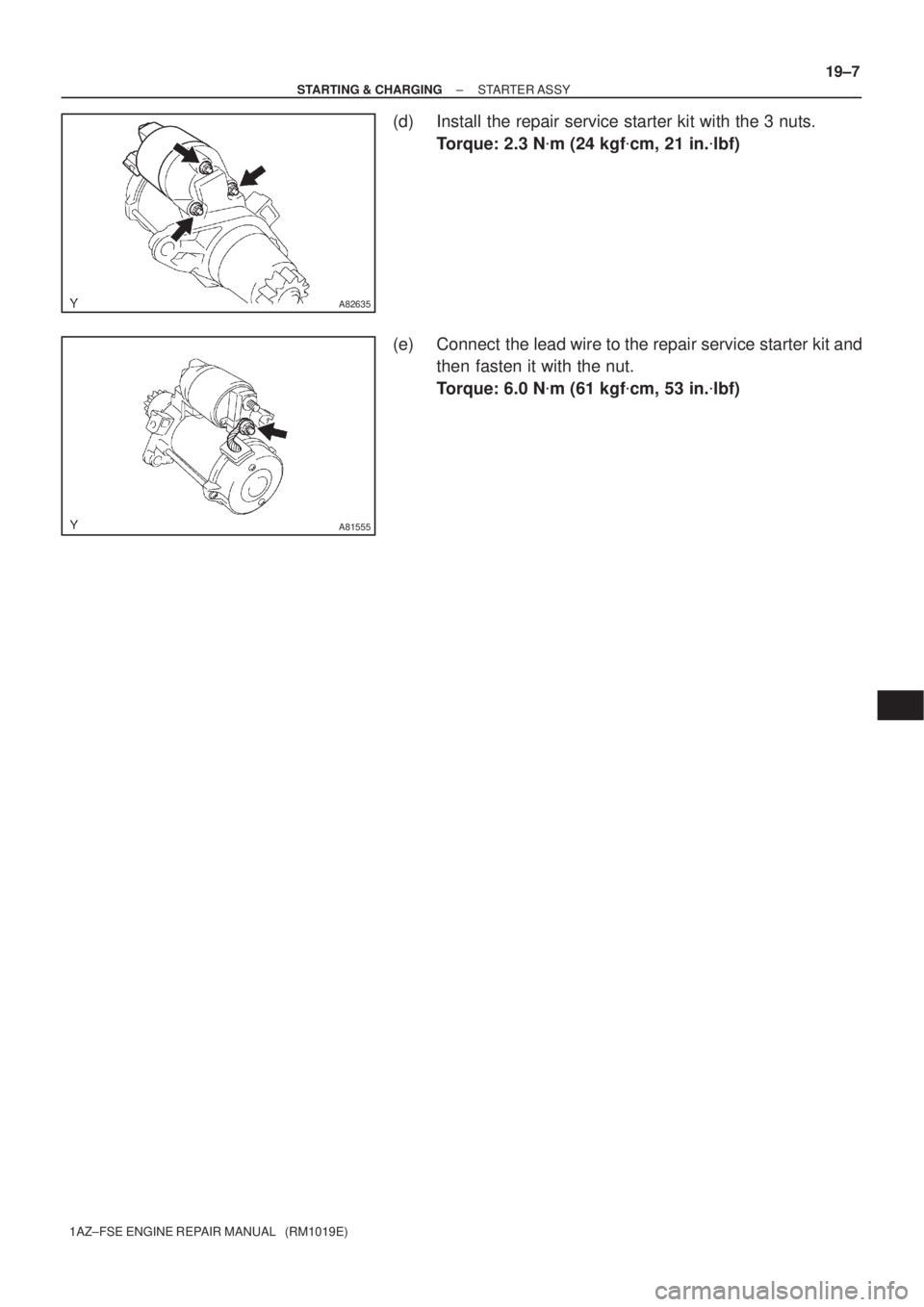
(d) Install the repair service starter kit with the 3 nuts.
Torque: 2.3 N�m (24 kgf�cm, 21 in.�lbf)
(e) Connect the lead wire to the repair service starter kit and
then fasten it with the nut.
Torque: 6.0 N�m (61 kgf�cm, 53 in.�lbf)
Page 3513 of 5135
 ISC
Idle Speed Control±
KSKnock SensorKnock Sensor
MAFMass Air FlowAir Flow Meter
MAPManifold Absolute")
± INTRODUCTIONTERMS FOR MANUAL TRANSAXLE REPAIR MANUAL
01±7
C250 M/T REPAIR MANUAL (RM1020E) ISC
Idle Speed Control±
KSKnock SensorKnock Sensor
MAFMass Air FlowAir Flow Meter
MAPManifold Absolute PressureManifold Pressure
Intake Vacuum
MCMixture Control
Electric Bleed Air Control Valve (EBCV)
Mixture Control Valve (MCV)
Electric Air Control Valve (EACV)
MDPManifold Differential Pressure±
MFIMultiport Fuel InjectionElectronic Fuel Injection (EFI)
MILMalfunction Indicator LampCheck Engine Light
MSTManifold Surface temperature±
MVZManifold Vacuum Zone±
NVRAMNon±Volatile Random Access Memory±
O2SOxygen SensorOxygen Sensor, O2 Sensor (O2S)
OBDOn±Board DiagnosticOn±Board Diagnostic (OBD)
OCOxidation Catalytic ConverterOxidation Catalyst Converter (OC), CC0
OPOpen LoopOpen Loop
PAIRPulsed Secondary Air InjectionAir Suction (AS)
PCMPowertrain Control Module±
PNPPark/Neutral Position±
PROMProgrammable Read Only Memory±
PSPPower Steering Pressure±
PTOXPeriodic Trap OxidizerDiesel Particulate Filter (DPF)
Diesel Particulate Trap (DPT)
RAMRandom Access MemoryRandom Access Memory (RAM)
RMRelay Module±
ROMRead Only MemoryRead Only Memory (ROM)
RPMEngine SpeedEngine Speed
SCSuperchargerSupercharger
SCBSupercharger Bypass±
SFISequential Multiport Fuel InjectionElectronic Fuel Injection (EFI), Sequential Injection
SPLSmoke Puff Limiter±
SRIService Reminder Indicator±
SRTSystem Readiness Test±
STScan Tool±
TBThrottle BodyThrottle Body
TBIThrottle Body Fuel InjectionSingle Point Injection
Central Fuel Injection (Ci)
TCTurbochargerTurbocharger
TCCTorque Converter ClutchTorque Converter
TCMTransmission Control ModuleTransmission ECU (Electronic Control Unit)
TPThrottle PositionThrottle Position
TRTransmission Range±
TVVThermal Vacuum ValveBimetallic Vacuum Switching Valve (BVSV)
Thermostatic Vacuum Switching Valve (TVSV)
TWCThree±Way Catalytic ConverterThree±Way Catalytic (TWC)
CC
RO
TWC+OCThree±Way + Oxidation Catalytic ConverterCCR + CCO
VA FVolume Air FlowAir Flow Meter
VRVoltage RegulatorVoltage Regulator
VSSVehicle Speed SensorVehicle Speed Sensor (Read Switch Type)
WOTWide Open ThrottleFull Throttle
Page 3807 of 5135
030KT±01
± SERVICE SPECIFICATIONSINTAKE
03±5
1CD±FTV ENGINE REPAIR MANUAL (RM927E)
TORQUE SPECIFICATION
Part tightenedN´mkgf´cmft´lbf
V Band8.38574 in.´lbf
Compressor housing x Bearing housing4.74842 in.´lbf
Turbocharger actuator x Compressor housing7.88069 in.´lbf
Compressor inlet elbow x Compressor housing2323517
Page 3868 of 5135

AVENSIS REPAIR MANUAL (RM1018E)
�Freeze frame data:
Freeze frame data records the engine condi")
3 2 1 45678
9 1 0 111 21 31 41 51 6
DLC3
A04550
FI0534
05±8
± DIAGNOSTICSSFI SYSTEM (1ZZ±FE/3ZZ±FE)
AVENSIS REPAIR MANUAL (RM1018E)
�Freeze frame data:
Freeze frame data records the engine conditions
(fuel system, calculator load, water temperature,
fuel trim, engine speed, vehicle speed, etc.) when
a malfunction is detected. When troubleshooting,
it is useful for determining whether the vehicle was
running or stopped, the engine was warmed up or
not, the air±fuel ratio was lean or rich, etc. at the
time of the malfunction.
(c) Check the DLC3.
The vehicle's ECM uses the ISO 9141±2 (Euro±OBD)/
ISO 14230(M±OBD) communication protocol. The termi-
nal arrangement of DLC3 complies with ISO 15031±03
and matches the ISO 9141±2/ ISO 14230 format.
Terminal No.Connection / Voltage or ResidenceCondition
7Bus + Line / Pulse generation+During transmission
4Chassis Ground ± Body Ground / 1 � or lessAlways
16Battery Positive ± Body Ground / 9 to 14 VAlways
HINT:
If the display shows ºUNABLE TO CONNECT TO VEHICLEº
when you have connected the cable of the hand±held tester to
the DLC3, turned the ignition switch ON and operated the
hand±held tester, there is a problem on the vehicle side or tool
side.
�If communication is normal when the tool is connected to
another vehicle, inspect the DLC3 on the original vehicle.
�If communication is still not possible is when the tool is
connected to another vehicle, the problem is probably in
the tool itself, so consult the Service Deparment listed in
the tool's instruction manual.
(d) Inspect the battery voltage.
Battery voltage: 11 to 14 V
If voltage is below 11V, recharge the battery before proceeding.
(e) Check the CHK ENG.
(1) The CHK ENG lamp comes on when the ignition
switch is turned ON and the engine is not running.
HINT:
If the CHK ENG lamp is not illuminated, troubleshoot the com-
bination meter.
(2) When the engine is started, the CHK ENG should
go off. If the lamp remains on, it means that the diag-
nosis system has detected a malfunction or ab-
normality in the system.

4. REMOVE STARTER ARMATURE PLATE
(a) Remove the a")

TORQUE SPECIFICATION
Part tightenedN´mkgf´cmft´lbf
V Band8.38574 in.´lbf
Compressor housing x Bearing housi")