Page 3403 of 5135
750N7±01
B66987
Back Door Trim Panel Assy Upper
Back Door Side Garnish LH Wiper Motor AssyRear Spoiler
Back Door Garnish Sub±assy Outside RH
Back Door Trim Board Assy
Door Pull Handle
Back Door Lock Striker Back Door Side Garnish RH
Door Pull Handle
: Specified torque
N´m (kgf´cm, ft´lbf)
Floor Finish Plate Rear Wiper Arm and Blade Assy
Wiper Arm Head Cap
5.5 (56, 49 in.´lbf)
Rear Wiper w/ Packing
Washer
Back Door
Stay Assy LH
7.0 (71, 62 in.´lbf)
22 (264, 19)
11.5 (120, 8)
Back Door Stay Assy RH
7.0 (71, 62 in.´lbf)
8.0 (82, 71 in.´lbf)
19.5 (200, 14)
Back Door Service Hole Cover
Back Door Lock Assy
4.9 (49, 43 in.´lbf)4.9 (49, 43 in.´lbf)
75±42
± ENGINE HOOD/DOORBACK DOOR (WAGON MODELS)
AVENSIS REPAIR MANUAL (RM1018E)
BACK DOOR (WAGON MODELS)
COMPONENTS
Page 3404 of 5135

AVENSIS REPAIR MANUAL (RM1018E)
OVERHAUL
HINT:
The installation is in the reverse o")
750N6±01
B66988: Clip
B66989: Clip
Hook
B66990: Clip
B66991
75±40
±
ENGINE HOOD/DOOR BACK DOOR(LIFTBACK MODELS)
AVENSIS REPAIR MANUAL (RM1018E)
OVERHAUL
HINT:
The installation is in the reverse order of the removal. However, when there is a special point concerning
the installation, it is indicated. 1.REMOVE BACK DOOR TRIM PANEL ASSY UPPER
(a)Using a screwdriver, disengage the 4 clips and removethe trim.
HINT:
Tape the screwdriver tip before use.
2.REMOVE BACK DOOR SIDE GARNISH LH
(a)Using a clip remover, remove the hook.
(b)Using a screwdriver, disengage the 2 clips and remove the side garnish.
HINT:
Tape the screwdriver tip before use.
3.REMOVE BACK DOOR SIDE GARNISH RH
HINT:
Use the same procedures described for the LH side.
4.REMOVE BACK DOOR TRIM BOARD ASSY
(a)Remove the 2 screws.
(b)Using a screwdriver, disengage the 12 clips and remove the trim board.
HINT:
Tape the screwdriver tip before use.
(c)Remove the 4 service hole covers.
5.REMOVE BACK DOOR DAMPER ASSY
(a)Remove the 4 bolts and damper.
6.REMOVE BACK DOOR GARNISH SUB±ASSY OUTSIDE RH (See page 76±27)
7.REMOVE REAR WIPER MOTOR ASSY (See page 66±17)
8.REMOVE CENTER STOP LAMP ASSY (See page 65±26)
Page 3408 of 5135
750N4±01
B66986
Back Door Trim
Panel Assy Upper
Back Door Trim Board Assy Back Door Side
Garnish LHBack Door Garnish Sub±assy
Outside RH
Floor Finish Plate Center Stop Lamp Assy
Back Door Lock Striker Hook
Back Door Side
Garnish RHBack Door Stay Assy RH
Back Door Lock Assy Rear Wiper Motor Assy
Back Door
Stay Assy LH
Back Door Service
Hole Cover
: Specified torqueN´m (kgf´cm, ft´lbf)
19.5 (200, 14)
5.5 (56, 49 in.´lbf)
Hook Rear Wiper Arm and Blade Assy
Rear Wiper
w/ Packing Washer
Wiper Arm Head Cap
Nut5.5 (56, 49 in.´lbf)
5.5 (56, 49 in.´lbf)
Cushion Rubber
Cushion Rubber
Rope Hook Assy
11.5 (120, 8)
22 (264, 19)
7.0 (71, 62 in.´lbf)
5.5 (56, 49 in.´lbf)
8.0 (82, 71 in.´lbf)
7.0 (71, 62 in.´lbf)22 (264, 19)
Female
Stopper RH
Female
Stopper LH
4.9 (49, 43 in.´lbf)Back Door Damper Assy
5.5 (56, 49 in.´lbf)
± ENGINE HOOD/DOORBACK DOOR (LIFTBACK MODELS)
75±37
AVENSIS REPAIR MANUAL (RM1018E)
BACK DOOR (LIFTBACK MODELS)
COMPONENTS
Page 3440 of 5135
760W7±01
B67608
Tape
Tape
76±24
±
EXTERIOR/INTERIOR TRIM REAR DOOR BELT MOULDING ASSY LH
AVENSIS REPAIR MANUAL (RM1018E)
REAR DOOR BELT MOULDING ASSY LH
REPLACEMENT
HINT:
�The installation is in the reverse order of the removal.
�On the RH side, use the same procedures as on the LH side.
1.REMOVE REAR DOOR WINDOW REGULATOR HANDLE ASSY (See page 75±22)
2.REMOVE REAR DOOR TRIM BASE LH (See page 75±22)
3. REMOVE POWER WINDOW REGULATOR SWITCH ASSY REAR (W/ POWER WINDOW) (See page 75±22)
4.REMOVE REAR DOOR TRIM BOARD SUB±ASSY LH (See page 75±22)
5.REMOVE REAR DOOR GLASS WEATHERSTRIP INNER LH (See page 75±22)
6.REMOVE REAR DOOR SERVICE HOLE COVER LH (See page 75±22)
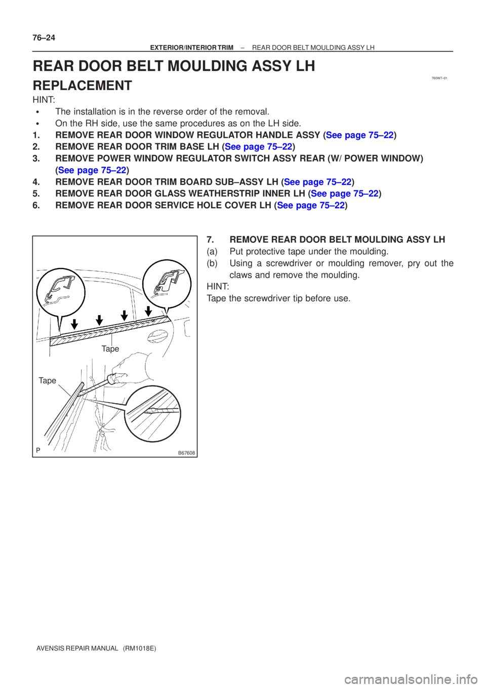
7. REMOVE REAR DOOR BELT MOULDING ASSY LH
(a) Put protective tape under the moulding.
(b) Using a screwdriver or moulding remover, pry out theclaws and remove the moulding.
HINT:
Tape the screwdriver tip before use.
Page 3457 of 5135
031FL±01
± SERVICE SPECIFICATIONSLUBRICATION
03±9
1AZ±FSE ENGINE REPAIR MANUAL (RM1019E)
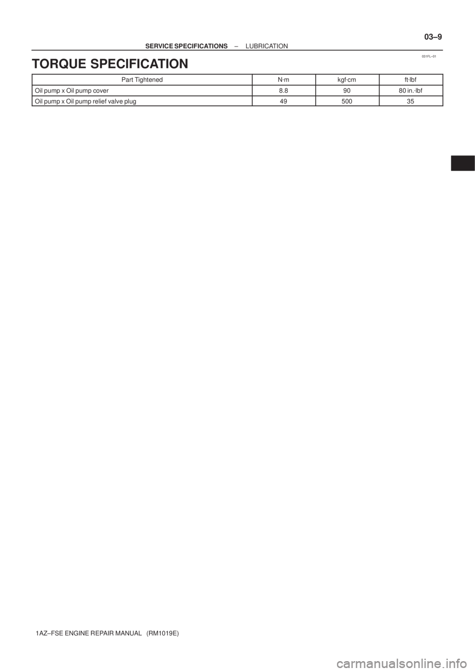
TORQUE SPECIFICATION
Part TightenedN�mkgf�cmft�lbf
Oil pump x Oil pump cover8.89080 in.�lbf
Oil pump x Oil pump relief valve plug4950035
Page 3460 of 5135
 HO2S
Heated Oxygen SensorHeated Oxygen Sensor (HO2S)
IACIdle Air ControlIdle Speed Control (ISC)
IATIntake Air TemperatureIntake o")
± INTRODUCTIONTERMS
01±13
1AZ±FSE ENGINE REPAIR MANUAL (RM1019E) HO2S
Heated Oxygen SensorHeated Oxygen Sensor (HO2S)
IACIdle Air ControlIdle Speed Control (ISC)
IATIntake Air TemperatureIntake or Inlet Air Temperature
ICMIgnition Control Module±
IFIIndirect Fuel InjectionIndirect Injection (IDL)
IFSInertia Fuel±Shutoff±
ISCIdle Speed Control±
KSKnock SensorKnock Sensor
MAFMass Air FlowAir Flow Meter
MAPManifold Absolute PressureManifold Pressure Intake Vacuum
MCMixture Control
Electric Bleed Air Control Valve (EBCV)
Mixture Control Valve (MCV)
Electric Air Control Valve (EACV)
MDPManifold Differential Pressure±
MFIMultiport Fuel InjectionElectronic Fuel Injection (EFI)
MILMalfunction Indicator LampCheck Engine Lamp
MSTManifold Surface Temperature±
MVZManifold Vacuum Zone±
NVRAMNon±Volatile Random Access Memory±
O2SOxygen SensorOxygen Sensor, O2 Sensor (O2S)
OBDOn±Board DiagnosticOn±Board Diagnostic System (OBD)
OCOxidation Catalytic ConverterOxidation Catalyst Convert (OC), CCo
OPOpen LoopOpen Loop
PAIRPulsed Secondary Air InjectionAir Suction (AS)
PCMPowertrain Control Module±
PNPPark/Neutral Position±
PROMProgrammable Read Only Memory±
PSPPower Steering Pressure±
PTOXPeriodic Trap OxidizerDiesel Particulate Filter (DPF)
Diesel Particulate Trap (DPT)
RAMRandom Access MemoryRandom Access Memory (RAM)
RMRelay Module±
ROMRead Only MemoryRead Only Memory (ROM)
RPMEngine SpeedEngine Speed
SCSuperchargerSupercharger
SCBSupercharger BypassE±ABV
SFISequential Multiport Fuel InjectionElectronic Fuel Injection (EFI), Sequential Injection
SPLSmoke Puff Limiter±
SRIService Reminder Indicator±
SRTSystem Readiness Test±
STScan Tool±
TBThrottle BodyThrottle Body
TBIThrottle Body Fuel InjectionSingle Point Injection
Central Fuel Injection (Ci)
TCTurbochargerTurbocharger
TCCTorque Converter ClutchTorque Converter
Page 3465 of 5135
Abbreviations Meaning
OHCOverhead Camshaft
OHVOverhead Valve
OPTOption
ORVROn±board Refilling Vapor Recovery
O/SOversize
P & BVPro")
01±10
± INTRODUCTIONTERMS
1AZ±FSE ENGINE REPAIR MANUAL (RM1019E)Abbreviations Meaning
OHCOverhead Camshaft
OHVOverhead Valve
OPTOption
ORVROn±board Refilling Vapor Recovery
O/SOversize
P & BVProportioning And Bypass Valve
PCSPower Control System
PCVPositive Crankcase Ventilation
PKBParking Brake
PPSProgressive Power Steering
PTCPositive Temperature Coefficient
PSPower Steering
PTOPower Take±Off
P/WPower Window
R & PRack And Pinion
RAMRandom Access Memory
R/BRelay Block
RBSRecirculating Ball Type Steering
R/FReinforcement
RFSRigid Front Suspension
RHRight±Hand
RHDRight±Hand Drive
RLYRelay
ROMRead Only Memory
RrRear
RRSRigid Rear Suspension
RWDRear±Wheel Drive
SDNSedan
SENSensor
SICSStarting Injection Control System
SOCState Of Charge
SOHCSingle Overhead Camshaft
SPECSpecification
SPISingle Point Injection
SRSSupplemental Restraint System
SSMSpecial Service Materials
SSTSpecial Service Tools
STDStandard
STJCold±Start Fuel Injection
SWSwitch
SYSSystem
T/ATransaxle
TACHTachometer
TBIThrottle Body Electronic Fuel Injection
TCTurbocharger
TCCSTOYOTA Computer±Controlled System
TCVTiming Control Valve
TDCTop Dead Center
TEMP.Temperature
TEMSTOYOTA Electronic Modulated Suspension
TFTToyota Free±Tronic
Page 3468 of 5135
190OI±01
A81555
A82635
A82636
A82637
19±2
± STARTING & CHARGINGSTARTER ASSY
1AZ±FSE ENGINE REPAIR MANUAL (RM1019E)
OVERHAUL
1. REMOVE REPAIR SERVICE STARTER KIT
(a) Remove the nut, and disconnect the lead wire from the re-
pair service starter kit.
(b) Remove the 3 nuts holding the repair service starter kit to
the starter housing.
(c) Remove the repair service starter kit.
(d) Remove the return spring and plunger.
2. REMOVE STARTER YOKE ASSY
(a) Using a torx driver T25, remove the 2 through bolts and
pull out the starter yoke together with the starter commu-
tator end frame.
(b) Remove the starter yoke from the starter commutator end
frame.
3. REMOVE STARTER ARMATURE ASSY
(a) Remove the starter armature assy from the starter yoke assy.


OVERHAUL
1. REMOVE REPAIR SERVICE STARTER KIT
(a) Remove the nut, and disconnec")