Page 298 of 5135
05±164
±
DIAGNOSTICS SFI SYSTEM (1AZ±FE)
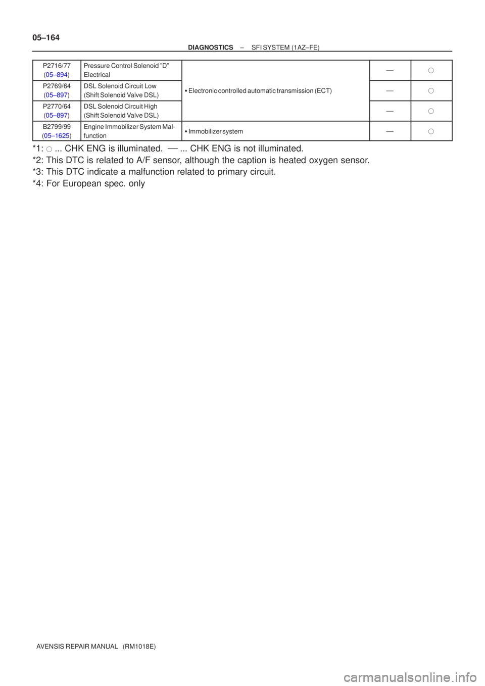
AVENSIS REPAIR MANUAL (RM1018E) P2716/77
(05±894)
Pressure Control Solenoid ºDº
Electrical��
P2769/64(05±897)DSL Solenoid Circuit Low
(Shift Solenoid Valve DSL)� Electronic controlled automatic transmission (ECT)��
P2770/64
(05±897)DSL Solenoid Circuit High
(Shift Solenoid Valve DSL)��
B2799/99
(05±1625)Engine Immobilizer System Mal-
function� Immobilizer system��
*1: � ... CHK ENG is illuminated. � ... CHK ENG is not illuminated.
*2: This DTC is related to A/F sensor, although the caption is heated oxygen sensor.
*3: This DTC indicate a malfunction related to primary circuit.
*4: For European spec. only
Page 299 of 5135

05C6L±01
ENGINE CONTROL SYSTEM Check Sheet
Customer's Name
Driver's Name
Date Vehicle
Brought in
License No.
VIN
Production Date
Licence No.
Odometer Reading
km
miles
Problem Symptoms
Engine does
not Start
Difficult to
Start
Poor Idling
Poor
Driveability
Engine Stall
Others
Engine does not crankNo initial combustionNo complete combustion
Engine cranks slowly
Other
Incorrect first idleIdling rpm is abnormalHigh ( rpm)Low ( rpm)
Rough idling
Other
HesitationBack fireMuffler explosion (after±fire)Surging
Knocking
Other
Soon after startingAfter accelerator pedal depressed
After accelerator pedal released
During A/C operation
Shifting from N to D
Other
Data Problem
Occurred
Problem Frequency
Condition When
Problem Occurs
Weather
Engine Operation
Engine Temp. Place Outdoor
TemperatureConstant
Sometimes ( times per day/month)Once only
Other
Fine
CloudyRainySnowyVarious/Other
Hot
Warm Cool
HighwaySuburbsInner CityUphillDownhill
Rough road
Other
Cold
Warming upAfter Warming upAny temp.Other
Starting
Just after starting ( min.)IdlingRacing
Driving
Constant speedAccelerationDeceleration
A/C switch ON/OFF
Other
Condition of check engine warning light
(CHK ENG)Remains on Sometimes lights up Does not light up
Normal Malfunction code(s) (code )
Freeze frame data ( )
Normal Malfunction code(s) (code )
Freeze frame data ( )
Normal mode
(Pre±check)
Check Mode DTC InspectionInspector's
Name
Cold (approx. �C/ �F)
05±148
± DIAGNOSTICSSFI SYSTEM (1AZ±FE)
AVENSIS REPAIR MANUAL (RM1018E)
CUSTOMER PROBLEM ANALYSIS CHECK
Page 300 of 5135
05C7H±01
±
DIAGNOSTICS SFI SYSTEM(1AZ±FE)
05±143
AVENSIS REPAIR MANUAL (RM1018E)
SFI SYSTEM(1AZ±FE)
HOW TO PROCEED WITH TROUBLESHOOTING
When using hand±held tester, troubleshoot in accordance with the procedure
shown below.
1VEHICLE BROUGHT TO WORKSHOP
2CUSTOMER PROBLEM ANALYSIS (See page 05±148)
3CONNECT THE HAND±HELD TESTER TO DLC3
HINT:
If the display indicates a communication fault in the tool, inspect DLC3.
4CHECK DTC AND FREEZE FRAME DATA(See page 05±149)
HINT:
Record or print DTC and freeze frame data, if needed.
5CLEAR DTC AND FREEZE FRAME DATA (See page 05±149)
6VISUAL INSPECTION
7SETTING THE CHECK (TEST) MODE DIAGNOSIS (See page 05±149)
8 PROBLEM SYMPTOM CONFIRMATION
HINT:
If the engine does not start, perform steps 10 and 12 first.
AMalfunction does not occur
BMalfunction occurs
B GO TO STEP 10
A
Page 301 of 5135
05±144
±
DIAGNOSTICS SFI SYSTEM(1AZ±FE)
AVENSIS REPAIR MANUAL (RM1018E)
9SYMPTOM SIMULATION
10DTC CHECK (See page 05±149)
AMalfunction code
BNo code
BGO TO STEP 12
A
11DTC CHART (See page 05±161)
GO TO STEP 14
12BASIC INSPECTION (See page 05±149)
AWrong parts not confirmed
BWrong parts confirmed
BGO TO STEP 17
A
13PROBLEM SYMPTOMS TABLE (See page 05±168)
AWrong circuit confirmed
BWrong parts confirmed
B GO TO STEP 17
A
14CHECK ECM POWER SOURCE CIRCUIT (See page 05±257)
15 CIRCUIT INSPECTION
AMalfunction not confirmed
BMalfunction confirmed
B GO TO STEP 18
A
Page 302 of 5135
±
DIAGNOSTICS SFI SYSTEM(1AZ±FE)
05±145
AVENSIS REPAIR MANUAL (RM1018E)
16CHECK FOR INTERMITTENT PROBLEMS (See page 05±149)
GO TO STEP 18
17 PARTS INSPECTION
18 IDENTIFICATION OF PROBLEM
19 ADJUSTMENT, REPAIR
20 CONFIRMATION TEST
END
Page 303 of 5135
05±146
±
DIAGNOSTICS SFI SYSTEM(1AZ±FE)
AVENSIS REPAIR MANUAL (RM1018E)
When not using hand±held tester, troubleshoot in accordance with the proce-
dure shown below.
1VEHICLE BROUGHT TO WORKSHOP
2CUSTOMER PROBLEM ANALYSIS (See page 05±148)
3CHECK AND CLEAR DTC (See page 05±149)
4PROBLEM SYMPTOM CONFIRMATION
AMalfunction occurs
BMalfunction does not occur
BSYMPTOM SIMULATION (See page 01±22)
A
5DTC CHECK (See page 05±149)
AMalfunction code
BNo code
B GO TO STEP 7
A
6DTC CHART (See page 05±161)
GO TO STEP 9
7BASIC INSPECTION (See page 05±149)
AWrong parts not confirmed
BWrong parts confirmed
B GO TO STEP 12
A
Page 304 of 5135
±
DIAGNOSTICS SFI SYSTEM(1AZ±FE)
05±147
AVENSIS REPAIR MANUAL (RM1018E)
8PROBLEM SYMPTOMS TABLE (See page 05±168)
AWrong circuit confirmed
BWrong parts confirmed
BGO TO STEP 12
A
9CHECK ECM POWER SOURCE CIRCUIT (See page 05±257)
10CIRCUIT INSPECTION
AMalfunction not confirmed
BMalfunction confirmed
BGO TO STEP 13
A
11CHECK FOR INTERMITTENT PROBLEMS (See page 05±149)
GO TO STEP 13
12 PARTS INSPECTION
13 IDENTIFICATION OF PROBLEM
14 ADJUSTMENT, REPAIR
15 CONFIRMATION TEST
END
Page 305 of 5135
 W±B
(RHD)
(LHD)W±B
(LHD) (LHD)W±L
(LHD)
W±L W±L
(RHD)
(RHD) J21D
J20BDB DC173 Driver Sid")
A81014
4 D5
DLC3
CGTC13
W±BCBW±L20
E9TCECM
W±L
W±B J8
J/C
BB
J16
J/C
A
IP
IOCenter J/B
CA 36
A(RHD) W±B
(RHD)
(LHD)W±B
(LHD) (LHD)W±L
(LHD)
W±L W±L
(RHD)
(RHD) J21D
J20BDB DC173 Driver Side J/B
3 2 1 45678
9 1 0 111 21 31 41 51 6
DLC3
A04550
CG (±)TC (+)
DLC3
± DIAGNOSTICSSFI SYSTEM (1ZZ±FE/3ZZ±FE)
05±141
AVENSIS REPAIR MANUAL (RM1018E)
TC TERMINAL CIRCUIT
CIRCUIT DESCRIPTION
Terminals TC and CG are located in the DLC3. When connecting these terminals, DTCs in normal mode or
check mode can be read through the CHK ENG flashing in the combination meter.
WIRING DIAGRAM
INSPECTION PROCEDURE
HINT:
�Even though terminal TC is not connected to terminal CG, the CHK ENG blinks.
�For the above phenomenon, an open or short in the wire harness, or malfunction inside the ECM is
the likely cause.
1 CHECK DLC3(TC VOLTAGE)
(a) Turn the ignition switch ON.
(b) Measure the voltage between the terminals of the DLC3.
Standard:
Symbols (Terminal No.)Specified condition
TC (13) ± CG (4)9 to 14 V
OK Go to step 3
NG
05C6K±01

05±143
AVENSIS REPAIR MANUAL (RM1018E)
SFI SYSTEM(1AZ±FE)
HOW TO PROCEED WITH TROUBLESHOOTING
When using hand±held tester, troubleshoot in accordance")

AVENSIS REPAIR MANUAL (RM1018E)
9SYMPTOM SIMULATION
10DTC CHECK (See page 05±149)
AMalfunction code
BNo code
BGO TO STEP 12
A
11DTC CHART (See page 05±1")

05±145
AVENSIS REPAIR MANUAL (RM1018E)
16CHECK FOR INTERMITTENT PROBLEMS (See page 05±149)
GO TO STEP 18
17 PARTS INSPECTION
18 IDENTIFICATION OF PROBLEM
19 ADJU")

AVENSIS REPAIR MANUAL (RM1018E)
When not using hand±held tester, troubleshoot in accordance with the proce-
dure shown below.
1VEHICLE BROUGHT TO WORKSHOP")

05±147
AVENSIS REPAIR MANUAL (RM1018E)
8PROBLEM SYMPTOMS TABLE (See page 05±168)
AWrong circuit confirmed
BWrong parts confirmed
BGO TO STEP 12
A
9CHECK ECM POWE")