Page 322 of 5135
������
�
A79065
Engine Room R/B No.4
EFI No.1 Fuse
B16200
± DIAGNOSTICSSFI SYSTEM (1ZZ±FE/3ZZ±FE)
05±129
AVENSIS REPAIR MANUAL (RM1018E)
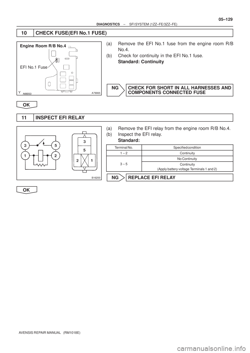
10 CHECK FUSE(EFI No.1 FUSE)
(a) Remove the EFI No.1 fuse from the engine room R/B
No.4.
(b) Check for continuity in the EFI No.1 fuse.
Standard: Continuity
NG CHECK FOR SHORT IN ALL HARNESSES AND
COMPONENTS CONNECTED FUSE
OK
11 INSPECT EFI RELAY
(a) Remove the EFI relay from the engine room R/B No.4.
(b) Inspect the EFI relay.
Standard:
Terminal No.Specified condition
1 ± 2Continuity
No Continuity
3 ± 5Continuity
(Apply battery voltage Terminals 1 and 2)
NG REPLACE EFI RELAY
OK
Page 323 of 5135

AVENSIS REPAIR MANUAL")
A66053
Engine Room R/B No.4
EFI Relay
������
�
A79066
Engine Room R/B No.4
EFI No.1 Fuse
1
2
A65748
MREL
E9
ECM Connector
+B
05±130
± DIAGNOSTICSSFI SYSTEM (1ZZ±FE/3ZZ±FE)
AVENSIS REPAIR MANUAL (RM1018E)
12 CHECK HARNESS AND CONNECTOR(EFI RELAY ± ECM, EFI RELAY ± BODY
GROUND)
(a) Check the harness and connector between the EFI relay
and ECM connector.
(1) Remove the EFI relay from the engine room R/B
No.4.
(2) Remove the EFI No.1 fuse from the engine room
R/B No.4.
(3) Disconnect the E9 ECM connector.
(4) Check for continuity between the wire harness side
connectors.
Standard (Check for open):
Symbols (Terminal No.)Specified condition
EFI relay (1) ± MREL (E9±8)
EFI relay (3) ± EFI No.1 fuse (1)Continuity
EFI No.1 fuse (2) ± +B (E9±1)
y
Standard (Check for short):
Symbols (Terminal No.)Specified condition
EFI relay (1) or MREL (E9±8) ± Body ground
EFI relay (3) or EFI No.1 fuse (1) ± Body groundNo continuity
EFI No.1 fuse (2) or +B (E9±1) ± Body ground
y
(b) Check the harness and connector between the EFI relay
and body ground.
(1) Remove the EFI relay from the engine room J/B
No.4.
(2) Check for continuity between the wire harness side
connector and the body ground.
Standard (Check for open):
Symbols (Terminal No.)Specified condition
EFI relay (2) ± Body groundContinuity
OK REPAIR OR REPLACE HARNESS OR
CONNECTOR
NG
CHECK AND REPAIR HARNESS AND CONNECTOR (TERMINAL +B OF ECM ± BATTERY POS-
ITIVE TERMINAL)
Page 324 of 5135
Heated Oxygen Sensor
EFI Relay
Heater
SensorOX1B HT1BECM
From
Battery EFI Fuse
O1B±
MREL
EFI No.2 Fuse
05±218
±
DIAGNOSTICS SFI SYSTEM(1AZ±")
���\b�A79115
Reference (Bank 1 Sensor 2 System Drawing)Heated Oxygen Sensor
EFI Relay
Heater
SensorOX1B HT1BECM
From
Battery EFI Fuse
O1B±
MREL
EFI No.2 Fuse
05±218
±
DIAGNOSTICS SFI SYSTEM(1AZ±FE)
AVENSIS REPAIR MANUAL (RM1018E)
DTCP0141/27OXYGEN SENSOR HEATER CIRCUIT MALFUNCTION (BANK 1 SENSOR 2)
DTCP0161/29OXYGEN SENSOR HEATER CIRCUIT (BANK 2 SENSOR 2)
CIRCUIT DESCRIPTION
Refer to DTC P0136/27 on page 05±211.
HINT:
The ECM provides a pulse width modulated control circuit to adjust current \
through the heater. The heated
oxygen sensor heater circuit uses a relay on the B+ side of the circuit.
DTC No.DTC Detection ConditionTrouble Area
P0141/27
Heated current is 0.2 A or less when heater operates
(1 trip detection logic)�Open or short in heater circuit of heated oxygen sensor
� Heated oxygen sensor heater
P0141/27
P0161/29When heater operates, heated current exceeds 2 A
(1 trip detection logic)
yg
�EFI relay
� ECM
HINT:
�Bank 1 refers to the bank that includes cylinder No.1.
�Bank 2 refers to the bank that does not include cylinder No.1.
�Sensor 1 refers to the sensor closest to the engine assembly.
�Sensor 2 refers to the sensor farthest away from the engine assembly.
WIRING DIAGRAM
Refer to DTC P0136/27 on page 05±211.
INSPECTION PROCEDURE
HINT:
�If different DTCs that are related to a different system are output simultaneously while terminal E2 is
used as a ground terminal, terminal E2 may be open.
�Read freeze frame data using �
\f
���
\f�� �\f��\f�� Freeze frame data records the engine conditions
when a malfunction is detected. When troubleshooting, it is useful for d\
etermining whether the vehicle
was running or stopped, the engine was warmed up or not, the air±fuel ra\
tio was lean or rich, etc. at
the time of the malfunction.
05C6Y±01
Page 325 of 5135
HT2B (+)E01 (±)E13
E10
ECM Connector
±
DIAGNOSTICS SFI SYSTEM(1AZ±FE)
05±219")
23
4 1
A79117
+B
HT
Bank 1
Sensor 2
Bank 2
Sensor 2 H8
H10
Heated Oxygen Sensor Connector
E1
OX
B16200
A18294
HT1B (+)HT2B (+)E01 (±)E13
E10
ECM Connector
±
DIAGNOSTICS SFI SYSTEM(1AZ±FE)
05±219
AVENSIS REPAIR MANUAL (RM1018E)
1INSPECT HEATED OXYGEN SENSOR(HEATER RESISTANCE)
(a)Disconnect the heated oxygen sensor connector.
(b)Inspect the heated oxygen sensor.
Standard:
Symbols (Terminal No.)ConditionSpecified condition
HT (H8±1) ± +B (H8±2)20�C (68 �F)11 to 16 �
HT (H8±1) ± E1 (H8±4)�No Continuity
HT (H10±1) ± +B (H10±2)20�C (68 �F)11 to 16 �
HT (H10±1) ± E1 (H10±4)�No Continuity
NGREPLACE HEATED OXYGEN SENSOR
OK
2INSPECT EFI RELAY
(a)Remove the EFI relay from the engine room R/B.
(b)Inspect the EFI relay. Standard:
Terminal No.Specified condition
1 ± 2Continuity
No Continuity
3 ± 5Continuity
(Apply battery voltage terminals 1 and 2)
NGREPLACE EFI RELAY
OK
3INSPECT ECM(HT1B OR HT2B VOLTAGE)
(a)Turn the ignition switch ON.
(b)Measure the voltage between the applicable terminals of the E10 and E13 ECM connector.
Standard:
Symbols (Terminal No.)Specified condition
HT1B (E10±4) ± E01 (E13±7)9to14VHT2B (E10±3) ± E01 (E13±7)9 to 14 V
HINT:
�The HT1B means the heated oxygen sensor bank 1 sen-
sor 2.
�The HT2B means the heated oxygen sensor bank 2 sen-
sor 2.
OKCHECK AND REPLACE ECM (See page 01±32)
NG
Page 326 of 5135
������
�
A79069
Engine Room R/B No.4
EFI No.2 Fuse
05±220
± DIAGNOSTICSSFI SYSTEM (1AZ±FE)
AVENSIS REPAIR MANUAL (RM1018E)
4 CHECK FUSE(EFI No.2)
(a) Remove the EFI No.2 fuse from the engine room R/B
No.4.
(b) Check for continuity in the EFI No.4 fuse.
Standard: Continuity
NG CHECK FOR SHORT IN ALL HARNESS AND
COMPONENTS CONNECTED FUSE
OK
Page 327 of 5135

A79118
Wire Harness SideBank 1
Sensor 2
Bank 2
Sensor 2 H8
H10
Heated Oxygen Sensor Connector +B
HT
A65744
HT2B
E10
ECM Connector
HT1B
������
� �
A79070
Engine Room R/B No.4
1 2
EFI No.2 Fuse
A66053
Engine Room R/B No.4
EFI Relay
±
DIAGNOSTICS SFI SYSTEM(1AZ±FE)
05±221
AVENSIS REPAIR MANUAL (RM1018E)
5CHECK HARNESS AND CONNECTOR(HEATED OXYGEN SENSOR ± ECM,
HEATED OXYGEN SENSOR ± EFI RELAY)
(a)Check the harness and connector between the ECM and
heated oxygen sensor connectors.
(1)Disconnect the H8 or H10 heated oxygen sensorconnector.
(2)Disconnect the E10 ECM connector.
(3)Check for continuity between the wire harness side connectors.
Standard (Check for open):
Symbols (Terminal No.)Specified condition
HT (H8±1) ± HT1B (E10±4)ContinuityHT (H10±1) ± HT2B (E10±3)Continuity
Standard (Check for short):
Symbols (Terminal No.)Specified condition
HT (H8±1)or HT1B (E10±4) ± Body groundNocontinuityHT (H10±1)or HT2B (E10±3) ± Body groundNo continuity
(b)Check the harness and connector between the heated oxygen sensor connector and EFI relay.
(1)Disconnect the H8 or H10 heated oxygen sensorconnector.
(2)Remove the EFI No.2 fuse from the engine room
R/B No.4.
(3)Remove the EFI relay from the engine room R/B No.4.
(4)Check for continuity between the wire harness side connectors.
Standard (Check for open):
Symbols (Terminal No.)Specified condition
+B (H8±2) ± EFI No.2 fuse (2)
+B (H10±2) ± EFI No.2 fuse (2)Continuity
EFI No.2 fuse (1) ± EFI relay (3)
y
Standard (Check for short):
Symbols (Terminal No.)Specified condition
+B (H8±2) or EFI No.2 fuse (2) ± Body ground
+B (H10±2) or EFI No.2 fuse (2) ± Body groundNo continuity
EFI No.2 fuse (1) or EFI relay (3) ± Body ground
y
NGREPAIR OR REPLACE HARNESS OR CONNECTOR
OK
CHECK AND REPLACE ECM (See page 01±32)
Page 328 of 5135

Platinum ElectrodeHeater
Exhaust Gas
CoverIdeal Air±Fuel Mixture
Output Voltage
Richer ± Air Fuel Ratio ± Leaner Element
AA
± DIAGNOSTICS")
A66651A±A SectionAir Solid Electrolyte
(Zirconia Element)
Platinum ElectrodeHeater
Exhaust Gas
CoverIdeal Air±Fuel Mixture
Output Voltage
Richer ± Air Fuel Ratio ± Leaner Element
AA
± DIAGNOSTICSSFI SYSTEM (1AZ±FE)
05±211
AVENSIS REPAIR MANUAL (RM1018E)
DTC P0136/27 OXYGEN SENSOR CIRCUIT MALFUNCTION
(BANK 1 SENSOR 2)
DTC P0156/29 OXYGEN SENSOR CIRCUIT MALFUNCTION
(BANK 2 SENSOR 2)
CIRCUIT DESCRIPTION
The heated oxygen sensor is the lamination type. Compared to the conventional type, the sensor and heater
portions of the lamination type are narrower overall. Because the heat of the heater acts directly on the alumi-
na and zirconia (of the sensor portion) it accelerates the activation of the sensor.
To obtain a high purification rate for the CO, HC and NOx components of the exhaust gas, a three±way cata-
lytic converter is used. But for the most efficient use of the three±way catalytic converter, the air±fuel ratio
must be precisely controlled so that it is always close to the stoichiometric air±fuel ratio.
The heated oxygen sensor has the characteristic whereby its output voltage changes suddenly in the vicinity
of the stoichiometric air±fuel ratio. This is used to detect the oxygen concentration in the exhaust gas and
provide the ECM with feedback control the air±fuel ratio.
When the air±fuel ratio becomes LEAN, the oxygen concentration in the exhaust gas increases. And the
heated oxygen sensor informs the ECM of the LEAN condition (low voltage, i.e. less than 0.45 V).
When the air±fuel ratio is RICHER than the stoichiometric air±fuel ratio, the oxygen concentration in the ex-
haust gas is reduced. And the heated oxygen sensor informs the ECM of the RICH condition (high voltage,
i.e. more than 0.45 V). The ECM judges by the voltage output from the heated oxygen sensor whether the
air±fuel ratio is RICH or LEAN and controls the injection time accordingly. However, if the malfunction of the
heated oxygen sensor causes an output of abnormal voltage, the ECM becomes unable to perform accurate
air±fuel ratio control.
The heated oxygen sensors include a heater which heats the zirconia element. The heater is controlled by
the ECM. When the intake air volume is low (the temperature of the exhaust gas is low), current flows to the
heater in order to heat the sensor for the accurate oxygen concentration detection.
DTC NoDTC Detection ConditionTrouble Area
The following condition continues for 480 sec. or more:�Open or short in heated oxygen sensor (bank 1, 2 sensor 2)
circuitP0136/27
P0156/29
g
�During driving with the engine warmed up, voltage output of
the heated oxygen sensor remains at 0.45 V or more, or 0.60circuit
�Heated oxygen sensor (bank 1, 2 sensor 2)
Heated o gen sensor heater (bank 1 2 sensor 2)P0156/29the heated oxygen sensor remains at 0.45 V or more, or 0.60
V or less.�Heated oxygen sensor heater (bank 1, 2 sensor 2)
�EFI relay
05C6X±01
Page 329 of 5135
A76884
B±W
GR GR2
IE1
E98ECM
MREL
44
31Engine Room R/B No.4
4EFI No.2
4
1
2B±W
EA113
B±W
52EFI
RelayEngine Room
R/B No.4
44H8
Heated Oxygen Sensor
(Bank 1 Sensor 2)
2
43 1IK14
L4
E10HT1B
21
E12 OX1B
32
E13O1B± WB
(*1) B±W
B±WH10
Heated Oxygen Sensor
(Bank 2 Sensor 2)
21L±R10
IK1L±R3
HT2B
E10 J12BR
D
J/C EFI 2
1
1A 11B±YW±B
Engine
Room
R/B No.1
Engine
Room
J/B No.1
43R
G
(*1)29
OX2B E12
O2B± 31
E13
*1: Shielded
EF ECBR J12 J/CJ13BR
D
EJ13
E B±G
Engine Room
J/B No.4 4A
4B 1 1
B±G
FL MAIN
BatteryL 05±212
± DIAGNOSTICSSFI SYSTEM (1AZ±FE)
AVENSIS REPAIR MANUAL (RM1018E)
HINT:
�Bank 1 refers to the bank that includes cylinder No.1.
�Bank 2 refers to the bank that does not include cylinder No.1.
�Sensor 2 refers to the sensor farthest away from the engine assembly.
WIRING DIAGRAM


2
43 1IK14
L4
E10HT1B
21
E12 O")