Page 274 of 5135
B±W
EA113
B±W 2V5
VSV for EVAP
1 W±G E1312
EVP1ECM
Engine Room R/B No.4 EFI No.2
4 1 2
B±W
4
05±94
±
DIAGNOSTICS SFI SYSTEM (1ZZ±FE/3ZZ±FE")
A79073
From
Terminal 3 of
EFI Relay
(See Page 05±124)B±W
EA113
B±W 2V5
VSV for EVAP
1 W±G E1312
EVP1ECM
Engine Room R/B No.4 EFI No.2
4 1 2
B±W
4
05±94
±
DIAGNOSTICS SFI SYSTEM (1ZZ±FE/3ZZ±FE)
AVENSIS REPAIR MANUAL (RM1018E)
DTC P0443 EVAPORATIVE EMISSION CONTROL SYSTEM PURGE CONTROL VALVE CIRCUIT
MALFUNCTION
CIRCUIT DESCRIPTION
To reduce HC emissions, evaporated fuel from the fuel tank is routed through the charcoal canister to the
intake manifold for combustion in the cylinders.
The ECM changes the duty signal to the VSV for EVAP so that the intake quantity of HC emissions becomse
properly for the driving conditions (engine load, engine speed, vehicle speed, \
etc.) after the engine is
warmed up.
DTC No.DTC Detecting ConditionTrouble Area
P0443Proper response to ECM command does not occur (1 trip
detection logic)�Open or short in VSV for EVAP circuit
� VSV for EVAP
� ECM
WIRING DIAGRAM
INSPECTION PROCEDURE
HINT:
Read freeze frame data using \f�� �� ����\b� \f��\f�
� Freeze frame data records the engine conditions when
a malfunction is detected. When troubleshooting, it is useful for determi\
ning whether the vehicle was running
or stopped, the engine was warmed up or not, the air±fuel ratio was lea\
n or rich, etc. at the time of the mal-
function.
05C6D±01
Page 275 of 5135
 ECM Connector
E13
EVP1 (+)
±
DIAGNOSTICS SFI SYSTEM(1ZZ±FE/3ZZ±FE)
05±95
AVENSIS REPAIR MANUAL (RM1018E)
1PERFORM ACTIVE TEST BY HAND±HELD TEST")
A79090VSV is ONVSV is OFF
E
F E
F
A18294
E01 (±) ECM Connector
E13
EVP1 (+)
±
DIAGNOSTICS SFI SYSTEM(1ZZ±FE/3ZZ±FE)
05±95
AVENSIS REPAIR MANUAL (RM1018E)
1PERFORM ACTIVE TEST BY HAND±HELD TESTER(VSV FOR EVAP)
(a)Select the ACTIVE TEST mode on the hand±held tester.
(b)Disconnect the vacuum hose from the VSV for EVAP.
(c)Start the engine.
(d)When the VSV for EVAP is operated by the hand±held
tester, apply the disconnected hose to your finger to
check the suction.
Result:
VSV is ON: Disconnected port sucks.
VSV is OFF: Disconnected port does not suck.
OKCHECK FOR INTERMITTENT PROBLEMS
NG
2INSPECT ECM(CHECK VOLTAGE)
(a)Turn the ignition switch ON.
(b)Measure the voltage between the terminals of the E13 ECM connector.
Standard:
Symbols (Terminal No.)Specified condition
EVP1 (E13±12) ± E01 (E13±7)8 to 14 V
OKCHECK AND REPLACE ECM
NG
3INSPECT VACUUM SWITCHING VALVE ASSY NO.1
NGREPLACE VACUUM SWITCHING VALVE ASSY NO.1
OK
4CHECK FUSE(EFI No.2) (See page 05±45)
NG CHECK FOR SHORT IN ALL HARNESS AND COMPONENTS CONNECTED FUSE
OK
Page 276 of 5135
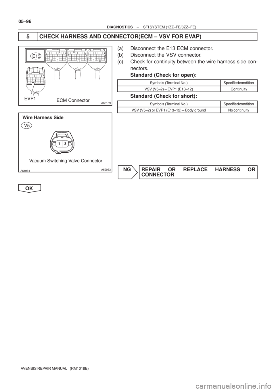
A65159EVP1
E13
ECM Connector
������A52933
Wire Harness Side
Vacuum Switching Valve Connector
V5
05±96
± DIAGNOSTICSSFI SYSTEM (1ZZ±FE/3ZZ±FE)
AVENSIS REPAIR MANUAL (RM1018E)
5 CHECK HARNESS AND CONNECTOR(ECM ± VSV FOR EVAP)
(a) Disconnect the E13 ECM connector.
(b) Disconnect the VSV connector.
(c) Check for continuity between the wire harness side con-
nectors.
Standard (Check for open):
Symbols (Terminal No.)Specified condition
VSV (V5±2) ± EVP1 (E13±12)Continuity
Standard (Check for short):
Symbols (Terminal No.)Specified condition
VSV (V5±2) or EVP1 (E13±12) ± Body groundNo continuity
NG REPAIR OR REPLACE HARNESS OR
CONNECTOR
OK
Page 277 of 5135

A66053
Engine Room R/B No.4EFI Relay
�����
�
A79070
Engine Room R/B No.4EFI No.2 Fuse
1
2
��\b��A52933
Wire Harness Side
Vacuum Switching Valve Connector
V5
±
DIAGNOSTICS SFI SYSTEM(1ZZ±FE/3ZZ±FE)
05±97
AVENSIS REPAIR MANUAL (RM1018E)
6CHECK HARNESS AND CONNECTOR(EFI RELAY ± VSV FOR EVAP)
(a)Remove the EFI relay from the engine room R/B No.4.
(b)Remove the EFI No.2 fuse from the engine room R/B
No.4.
(c)Disconnect the VSV connector.
(d)Check for continuity between the wire harness side con- nectors.
Standard (Check for open):
Symbols (Terminal No.)Specified condition
EFI relay (3) ± EFI No.2 fuse (1)ContinuityEFI No.2 fuse (2) ± VSV (V5±1)Continuity
Standard (Check for short):
Symbols (Terminal No.)Specified condition
EFI relay (3) or EFI No.2 fuse (1) ± Body groundNocontinuityEFI No.2 fuse (2) or VSV (V5±1) ± Body groundNo continuity
NOTICE:
Do not insert the tester leads hard in the procedure (c), the
holder may be damaged.
NGREPAIR OR REPLACE HARNESS OR CONNECTOR
OK
CHECK FOR ECM POWER SOURCE CIRCUIT (See page 05±124)
Page 278 of 5135

A58692
Waveform of heated oxygen
Sensor in front of CatalystNormal CatalystWaveform of Heated Oxygen
Sensor behind Catalyst
A58693
Engine Speed
2,500 ± 3,000 rpm
Idling
IG SW OFF
Warmed up 3 min. Check Time (a)(b)(c) (d)
± DIAGNOSTICSSFI SYSTEM (1ZZ±FE/3ZZ±FE)
05±91
AVENSIS REPAIR MANUAL (RM1018E)
DTC P0420 CATALYST SYSTEM EFFICIENCY BELOW
THRESHOLD (BANK 1)
CIRCUIT DESCRIPTION
The ECM compares the 2 waveforms of the heated oxygen sensors located before and after the catalyst
to determine whether or not the catalyst performance has deteriorated.
Air±fuel ratio feedback compensation keeps the waveform of the heated oxygen sensor in front of the cata-
lyst alternates between back and forth, from rich to lean.
If the catalyst is functioning normally, the waveform of the heated oxygen sensor behind the catalyst switches
back and forth between rich and lean much more slowly than the waveform of the heated oxygen sensor
in front of the catalyst.
When both waveforms change at a similar rate, it indicates that the catalyst performance has deteriorated.
DTC No.DTC Detecting ConditionTrouble Area
P0420
After engine and catalyst are warmed up, and while vehicle is
driven within set vehicle and engine speed range, waveforms
of heated oxygen sensors have same amplitude (2 trip detec-
tion logic)�Gas leakage in exhaust system
�Heated oxygen sensor
�Three±way catalytic converter
�ECM
CONFIRMATION DRIVING PATTERN
05B43±02
Page 279 of 5135

1.0 V
0 V 200 msec. /Division
05±92
±
DIAGNOSTICS SFI SYSTEM(1ZZ±FE/3ZZ±FE)
AVENSIS REPAIR MANUAL (RM1018E)
(a)Connect the hand±held tester to the DLC3,")
A58694
OX Signal Waveform (Oscilloscope)
1.0 V
0 V 200 msec. /Division
05±92
±
DIAGNOSTICS SFI SYSTEM(1ZZ±FE/3ZZ±FE)
AVENSIS REPAIR MANUAL (RM1018E)
(a)Connect the hand±held tester to the DLC3, or connect the probe of the oscilloscope between terminals HT1A,
HT1B, OX1A, OX1B and E1 of the ECM connector.
(b)Start the engine and warm it up with all the accessories switched OFF until the engine coolant temperature is
stable.
(c)Run the engine at 2,500 to 3,000 rpm for about 3 min.
(d)After confirming that the waveform of the heated oxygen
sensor (bank 1 sensor 1 (OX)) which oscillates around 0.5
V during feedback to the ECM, check the waveform of the
heated oxygen sensor (bank 1 sensor 2 (OX)).
HINT:
�If there is a malfunction in the system, the waveform of the
heated oxygen sensor (bank 1 sensor 2 (OX)) is similar
to the wave from of the heated oxygen sensor (bank 1
sensor 1 (OX)) snown in the diagram on the left.
�There are some cases that, even though a malfunction
exists, the CHK ENG may not be illuminated.
INSPECTION PROCEDURE
HINT:
Read freeze frame data using \f���� ����\b�\f��\f�
� Freeze frame data records the engine conditions when
a malfunction is detected. When troubleshooting, it is useful for determi\
ning whether the vehicle was running
or stopped, the engine was warmed up or not, the air±fuel ratio was lea\
n or rich, etc. at the time of the mal-
function.
1READ OUTPUT DTC(BESIDES P0420)
(a)Read the DTC using the hand±held tester. Result:
Display (DTC output)Proceed to
Only ºP0420º is outputA
ºP0420º and other DTCs are outputB
HINT:
If any other codes besides ºP0420º are output, perform the troublesh\
ooting for those DTCs first.
BGO TO RELEVANT DTC CHART(See page 05±16)
A
Page 280 of 5135
±
DIAGNOSTICS SFI SYSTEM(1ZZ±FE/3ZZ±FE)
05±93
AVENSIS REPAIR MANUAL (RM1018E)
2CHECK FOR EXHAUST GAS LEAKS
NGREPAIR OR REPLACE
OK
3INSPECT HEATED OXYGEN SENSOR(BANK 1 SENSOR 1) (See Page 12±3)
NG REPAIR OR REPLACE HEATED OXYGEN SENSOR
OK
4INSPECT HEATED OXYGEN SENSOR(BANK 1 SENSOR 2) (See Page 12±3)
NG REPAIR OR REPLACE HEATED OXYGEN SENSOR
OK
REPLACE THREE±WAY CATALYTIC CONVERTER
Page 281 of 5135

CH2
(NE+) GND
05±88
±
DIAGNOSTICS SFI SYSTEM(1ZZ±FE/3ZZ±FE)
AVENSIS REPAIR MANUAL (RM1018E)
DTCP0340CAMSHAFT POSITION SENSOR CIRCUIT MALFUNCTION
CIRCUIT DESCRIPTION
The camsh")
A63955
GND
CH1
(G2)
CH2
(NE+) GND
05±88
±
DIAGNOSTICS SFI SYSTEM(1ZZ±FE/3ZZ±FE)
AVENSIS REPAIR MANUAL (RM1018E)
DTCP0340CAMSHAFT POSITION SENSOR CIRCUIT MALFUNCTION
CIRCUIT DESCRIPTION
The camshaft position sensor (G2 signal) consists of a magnet, iron core \
and pickup coil.
The G2 signal plate has 3 teeth on its outer circumference and is instal\
led on the camshaft timing pulley.
When the camshafts rotate, the protrusion on the signal plate and the air gap on the pickup coil changes,
causing fluctuations in the magnetic field and generating an electromoti\
ve force in the pickup coil.
The NE signal plate (crankshaft timing pulley) has 34 teeth and is instal\
led to the crankshaft. The NE signal
sensor generates 34 signals at every engine revolution. The ECM detects \
the crankshaft angle and the en-
gine revolution based on the NE signals, and the cylinder and the angle of the VVT based on the combination
of the G2 and NE signals.
DTC No.DTC Detecting ConditionTrouble Area
P0340
�No camshaft position sensor signal to the ECM during crank-
ing
� Open in NE± circuit
�Open or short in camshaft position sensor circuit
� Camshaft position sensor
� Intake camshaft
� Timing chain has jumped a tooth
� ECM
Reference: Inspection using the oscilloscope.
HINT:
The correct waveform is as shown on the left.
ItemContents
TerminalCH1: G2 ± NE±
CH2: NE+ ± NE±
Equipment Set5V/DIV, 20ms/DIV
ConditionDuring cranking or idling
WIRING DIAGRAM
Refer to DTC P0335 on page05±84.
INSPECTION PROCEDURE
HINT:
Read freeze frame data using \f�� �� ����\b� \f��\f�
� Freeze frame data records the engine conditions when
a malfunction is detected. When troubleshooting, it is useful for determi\
ning whether the vehicle was running
or stopped, the engine was warmed up or not, the air±fuel ratio was lea\
n or rich, etc. at the time of the mal-
function.
05B42±03

05±93
AVENSIS REPAIR MANUAL (RM1018E)
2CHECK FOR EXHAUST GAS LEAKS
NGREPAIR OR REPLACE
OK
3INSPECT HEATED OXYGEN SENSOR(BANK 1 SENSOR 1) (See Page 12±3)")