Page 266 of 5135
B16200
05±108
± DIAGNOSTICSSFI SYSTEM (1ZZ±FE/3ZZ±FE)
AVENSIS REPAIR MANUAL (RM1018E)
Standard (Check for short):
Symbols (Terminal No.)Specified condition
IGT (I1±3) or IGT1 (E13±8) ± Body ground
IGT (I2±3) or IGT2 (E13±9) ± Body ground
IGT (I3±3) or IGT3 (E13±10) ± Body ground
IGT (I4±3) or IGT4 (E13±11) ± Body groundNo continuityIGF (I1±2) or IGF (E13±23) ± Body groundNo continuity
IGF (I2±2) or IGF (E13±23) ± Body ground
IGF (I3±2) or IGF (E13±23) ± Body ground
IGF (I4±2) or IGF (E13±23) ± Body ground
NG REPLACE HARNESS OR CONNECTOR
OK
REPLACE IGNITION COIL
5 INSPECT IG2 RELAY
(a) Remove the IG2 relay from the engine room R/B No.4.
(b) Inspect the IG2 relay.
Standard:
Terminal No.Specified condition
1 ± 2Continuity
No Continuity
3 ± 5Continuity
(Apply battery voltage Terminals 1 and 2)
NG REPLACE IG2 RELAY
OK
Page 267 of 5135

05±109
AVENSIS REPAIR MANUAL (RM1018E")
A54393
+B
Ignition Coil and Igniter Connector
Wire Harness Side
I1
I2I3I4
������A79064IG2 Relay
Engine Room R/B No.4
±
DIAGNOSTICS SFI SYSTEM(1ZZ±FE/3ZZ±FE)
05±109
AVENSIS REPAIR MANUAL (RM1018E)
6CHECK HARNESS AND CONNECTOR(IG2 RELAY ± IGNITION COIL)
(a)Disconnect the ignition coil and igniter connector.
(b)Remove the IG2 relay from the engine room R/B No.4.
(c)Check for continuity between the wire harness side con-
nectors.
Standard (Check for open):
Symbols (Terminal No.)Specified condition
+B (I1±1) ± IG2 relay (3)
+B (I2±1) ± IG2 relay (3)Continuity+B (I3±1) ± IG2 relay (3)Continuity
+B (I4±1) ± IG2 relay (3)
Standard (Check for short):
Symbols (Terminal No.)Specified condition
+B (I1±1) or IG2 relay (3) ± Body ground
+B (I2±1) or IG2 relay (3) ± Body groundNocontinuity+B (I3±1) or IG2 relay (3) ± Body groundNo continuity
+B (I4±1) or IG2 relay (3) ± Body ground
NGREPLACE HARNESS OR CONNECTOR
OK
7CHECK FUSE(IGN FUSE) (See page 05±124)
NG CHECK FOR SHORT IN ALL HARNESSES AND COMPONENTS CONNECTED FUSE
OK
Page 268 of 5135
A66267
IG2 Wire Harness Side
Ignition Switch Connector
I13
A79103
Driver Side J/B
IGN Fuse12
������A79064
Engine Room R/B No.4
IG2 Relay
05±110
± DIAGNOSTICSSFI SYSTEM (1ZZ±FE/3ZZ±FE)
AVENSIS REPAIR MANUAL (RM1018E)
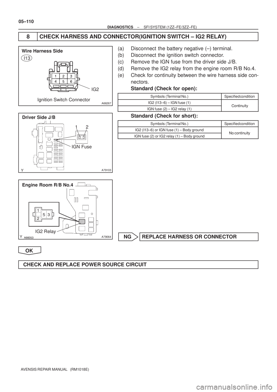
8 CHECK HARNESS AND CONNECTOR(IGNITION SWITCH ± IG2 RELAY)
(a) Disconnect the battery negative (±) terminal.
(b) Disconnect the ignition switch connector.
(c) Remove the IGN fuse from the driver side J/B.
(d) Remove the IG2 relay from the engine room R/B No.4.
(e) Check for continuity between the wire harness side con-
nectors.
Standard (Check for open):
Symbols (Terminal No.)Specified condition
IG2 (I13±6) ± IGN fuse (1)ContinuityIGN fuse (2) ± IG2 relay (1)Continuity
Standard (Check for short):
Symbols (Terminal No.)Specified condition
IG2 (I13±6) or IGN fuse (1) ± Body groundNo continuityIGN fuse (2) or IG2 relay (1) ± Body groundNo continuity
NG REPLACE HARNESS OR CONNECTOR
OK
CHECK AND REPLACE POWER SOURCE CIRCUIT
Page 269 of 5135

A79101
2 VISC DUTY1
GND 3
I10
ISC Valve
G±R5
E13 R")
A58697
Intake Air
Chamber
Throttle Valve
To Cylinder
ISC Valve
Valve
ECM
Signal From
Air
Cleaner
From
Terminal 2 of
EFI No.1 Fuse
(See Page 05±124)
A79101
2 VISC DUTY1
GND 3
I10
ISC Valve
G±R5
E13 RSDECM
B±R 12
EA1 B±R
W±B7
E13 E01
W±B
EG
05±100
±
DIAGNOSTICS SFI SYSTEM (1ZZ±FE/3ZZ±FE)
AVENSIS REPAIR MANUAL (RM1018E)
DTC P0505 IDLE CONTROL SYSTEM MALFUNCTION
CIRCUIT DESCRIPTION
The rotary solenoid type of the idle speed control (ISC) valve is
located under the throttle body and intake air bypassing the
throttle valve is directed to the ISC valve through the passage.
In this way the intake air volume bypassing the throttle valve is
regulated, controls the engine speed.
The ECM operates the ISC valve only to perform idle±up and
provide feedback for the target idling speed.
DTC No.DTC Detecting ConditionTrouble Area
P0505Idle speed continues to vary greatly from target speed
(1 trip detection logic)
� Open or short in ISC valve circuit
� ISC valve is stuck or closed
� PCV hose
� A/C switch circuit
� Air induction system
� ECM
WIRING DIAGRAM
INSPECTION PROCEDURE
HINT:
Read freeze frame data using \f�� �� ����\b� \f��\f�
� Freeze frame data records the engine conditions when
a malfunction is detected. When troubleshooting, it is useful for determi\
ning whether the vehicle was running
or stopped, the engine was warmed up or not, the air±fuel ratio was lea\
n or rich, etc. at the time of the mal-
function.
05B46±02
Page 270 of 5135
GND (±)
ISC valve Connector
Wire Harness Side
I10
±
DIAGNOSTICS SFI SYSTEM(1ZZ±FE/3ZZ±FE)
05±101
AVENSIS REPAIR MANUAL (RM1018E)
1PERFORM ACTIVE TEST USING HAND±HELD TESTER(C")
123
A66264VISC (+)GND (±)
ISC valve Connector
Wire Harness Side
I10
±
DIAGNOSTICS SFI SYSTEM(1ZZ±FE/3ZZ±FE)
05±101
AVENSIS REPAIR MANUAL (RM1018E)
1PERFORM ACTIVE TEST USING HAND±HELD TESTER(CHECK ISC VALVE
OPERATION)
(a)Warm up the engine to the normal operating temperature.
(b)Switch off all the accessories.
(c)Switch off the A/C.
(d)Shift the lever to the neutral position.
(e)Connect the hand±held tester to the DLC3 on the vehicle.
(f)Select the item ºDIAGNOSIS / OBD/MOBD / ACTIVE TEST / ISC DUTY RATIOº.
(g)Check that the engine RPM varies when changing the ISC duty ratio.
Engine RPM:
Engine RPM fluctuates ups and downs in respose to the ISC duty ratio var\
iation.
OKCHECK FOR INTERMITTENT PROBLEMS (See page 05±5)
NG
2 CHECK HARNESS AND CONNECTOR
(a) Disconnect the ISC valve connector.
(b) Turn the ignition switch ON.
(c) Measure the voltage between the terminals of the ISC valve wire harness side connector.
Standard:
Symbols (Terminal No.)Specified condition
VISC (I10±2) ± GND (I10±3)9 to 14 V
NG REPAIR OR REPLACE HARNESS OR CONNECTOR
OK
Page 271 of 5135
A65743
RSD
E13ECM Connector
E01
123
A66264
DUTY ISC valve Connector
Wire Harness SideGND
I10
05±102
±
DIAGNOSTICS SFI SYSTEM(1ZZ±FE/3ZZ±FE)
AVENSIS REPAIR MANUAL (RM1018E)
3CHECK HARNESS AND CONNECTOR(RSD CIRCUIT)
(a)Disconnect the ISC valve connector.
(b)Disconnect the E13 ECM connector.
(c)Check for continuity between the wire harness side con- nectors.
Standard (Check for open):
Symbols (Terminal No.)Specified condition
DUTY (I10±1) ± RSD (E13±5)ContinuityGND (I10±3) ± E01 (E13±7)Continuity
Standard (Check for short):
Symbols (Terminal No.)Specified condition
DUTY (I10±1)or RSD (E13±5) ± Body groundrNo continuity
NGREPAIR OR REPLACE HARNESS OR CONNECTOR
OK
4INSPECT THLOTTLE BODY IDLE SPEED CONTROL VALVE ASSY (See page 10±1)
NG REPLACE THLOTTLE BODY IDLE SPEED CONTROL VALVE ASSY
OK
CHECK AND REPLACE ECM (See page 01±32)
Page 272 of 5135

A79413
From
Speed SensorSkid
Control
ECU4±Pulse
Combination
Meter4±Pulse
ECM
A79092
C11
Combination Meter
Junction Connector
17
V±W
E10ECM
V±W
SPD 18
J10
J20 H
*1*2
*1: LHD
*2: RHD J20 J10
*1 *2 HHH 05±98
± DIAGNOSTICSSFI SYSTEM (1ZZ±FE/3ZZ±FE)
AVENSIS REPAIR MANUAL (RM1018E)
DTC P0500 VEHICLE SPEED SENSOR MALFUNCTION
CIRCUIT DESCRIPTION
The speed sensor for skid control ECU detects the wheel speed and sends the appropriate signals to the
skid control ECU.
The skid control ECU converts these signals into a 4±pulse signal and outputs it to the combination meter.
After this signal is converted into a more precise rectangular waveform by the waveform shaping circuit in-
side the combination meter, it is then transmitted to the ECM. The ECM determines the vehicle speed based
on the frequency of these pulse signals.
DTC No.DTC Detecting ConditionTrouble Area
P0500
During the vehicle is being driven, no vehicle speed sensor
signal to the ECM
(1 trip detection logic: A/T)
(2 trip detection logic: M/T)�Open or short in speed sensor circuit
�Speed sensor
�Combination meter
�ECM
�Skid control ECU
WIRING DIAGRAM
05B45±02
Page 273 of 5135
E1 (±)ECM Connector
E12 E10
A62954
Turn Wheel
4.5±5.5V
0V
±
DIAGNOSTICS SFI SYSTEM(1ZZ±FE/3ZZ±FE)
05±99
AVENSIS REPAIR MANUAL (RM1018E)
INSPECTION PROCEDURE
HINT:
Read freeze fra")
A18294
SPD (+)E1 (±)ECM Connector
E12 E10
A62954
Turn Wheel
4.5±5.5V
0V
±
DIAGNOSTICS SFI SYSTEM(1ZZ±FE/3ZZ±FE)
05±99
AVENSIS REPAIR MANUAL (RM1018E)
INSPECTION PROCEDURE
HINT:
Read freeze frame data using \f���� ����\b�\f��\f�
� Freeze frame data records the engine conditions when
a malfunction is detected. When troubleshooting, it is useful for determi\
ning whether the vehicle was running
or stopped, the engine was warmed up or not, the air±fuel ratio was lea\
n or rich, etc. at the time of the mal-
function.
1CHECK OPERATION OF SPEEDOMETER(SPEEDOMETER OPERATION)
(a)Drive the vehicle and check that the operation of the speedometer in the\
combination meter is normal.
HINT:
The vehicle speed sensor is operating normally if the speedometer display i\
s normal.
NGCHECK SPEEDOMETER CIRCUIT
OK
2INSPECT ECM(CHECK VOLTAGE)
(a)Shift the lever to the neutral position.
(b)Jack up the vehicle.
(c)Turn the ignition switch ON.
(d)Measure the voltage between the terminals of the E10 and E12 ECM connectors as the wheel is turned slowly.
Standard:
Symbols (Terminal No.)Specified condition
SPD (E10±17) ± E1 (E12±7)Generated intermittently
HINT:
The output voltage should fluctuate up and down similarly to the
diagram on the left when the wheel is turned slowly.
NGREPAIR OR REPLACE HARNESS AND CONNECTOR
OK
CHECK AND REPLACE ECM (See page 01±32)

AVENSIS REPAIR MANUAL (RM1018E)
Standard (Check for short):
Symbols (Terminal No.)Specified condition
IGT (I1±3) or IGT1 (E13±8) ± Body")

AVENSIS REPAIR MANUAL (RM1018E)
3CHECK HARNESS AND CON")