Page 4944 of 5135
05–184
– DIAGNOSTICSSFI SYSTEM (1ZZ–FE/3ZZ–FE)(From February, 2004)
AVENSIS REPAIR MANUAL SUPPLEMENT
(RM1098E)
DTC P2120 THROTTLE/PEDAL POSITION
SENSOR/SWITCH ”D” CIRCUIT
DTC P2122 THROTTLE/PEDAL POSITION
SENSOR/SWITCH ”D” CIRCUIT LOW INPUT
DTC P2123 THROTTLE/PEDAL POSITION
SENSOR/SWITCH ”D” CIRCUIT HIGH INPUT
DTC P2125 THROTTLE/PEDAL POSITION
SENSOR/SWITCH ”E” CIRCUIT
DTC P2127 THROTTLE/PEDAL POSITION
SENSOR/SWITCH ”E” CIRCUIT LOW INPUT
DTC P2128 THROTTLE/PEDAL POSITION
SENSOR/SWITCH ”E” CIRCUIT HIGH INPUT
DTC P2138 THROTTLE/PEDAL POSITION
SENSOR/SWITCH ”D”/”E” VOLTAGE
CORRELATION
HINT:
These DTCs are related to the accelerator pedal position sensor.
05KOD–02
Page 4945 of 5135

A71015
0
Accelerator Pedal Opening Angle (deg)125
VPA1 VPA2
5
Movable Range
Usable Range
Usable Range *1
*1
Movable Range
Usable Range
*2
Accelerator pedal released (15�)
Accelerator pedal depressed
(about 100�)
Accelerator Pedal
Position Sensor
Output Voltage (V)
VPA2VPA1 EP2
VCP2
*1:
*
2:
EP1
0.8
105
VCP1*2
*2*1
– DIAGNOSTICSSFI SYSTEM (1ZZ–FE/3ZZ–FE)(From February, 2004)
05–185
AVENSIS REPAIR MANUAL SUPPLEMENT
(RM1098E)
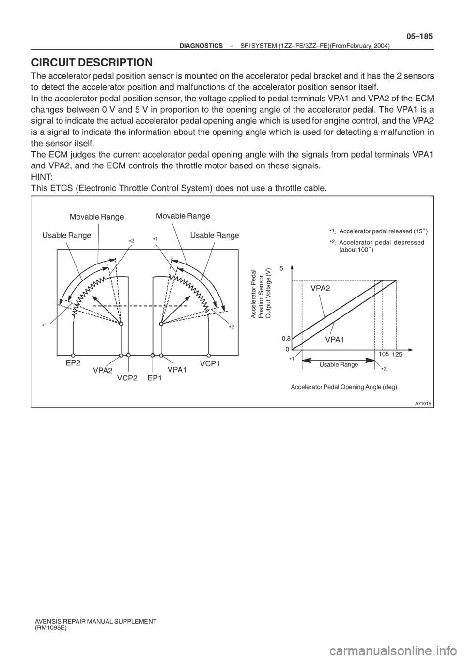
CIRCUIT DESCRIPTION
The accelerator pedal position sensor is mounted on the accelerator pedal bracket and it has the 2 sensors
to detect the accelerator position and malfunctions of the accelerator position sensor itself.
In the accelerator pedal position sensor, the voltage applied to pedal terminals VPA1 and VPA2 of the ECM
changes between 0 V and 5 V in proportion to the opening angle of the accelerator pedal. The VPA1 is a
signal to indicate the actual accelerator pedal opening angle which is used for engine control, and the VPA2
is a signal to indicate the information about the opening angle which is used for detecting a malfunction in
the sensor itself.
The ECM judges the current accelerator pedal opening angle with the signals from pedal terminals VPA1
and VPA2, and the ECM controls the throttle motor based on these signals.
HINT:
This ETCS (Electronic Throttle Control System) does not use a throttle cable.
Page 4946 of 5135

05–186
– DIAGNOSTICSSFI SYSTEM (1ZZ–FE/3ZZ–FE)(From February, 2004)
AVENSIS REPAIR MANUAL SUPPLEMENT
(RM1098E)DTC No.
DTC Detection ConditionTrouble Area
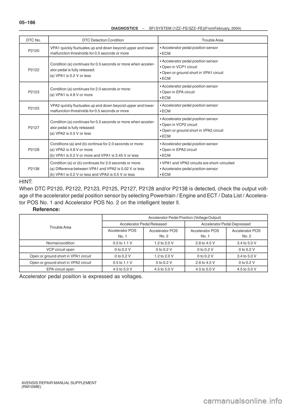
P2120VPA1 quickly fluctuates up and down beyond upper and lower
malfunction thresholds for 0.5 seconds or more�Accelerator pedal position sensor
�ECM
P2122
Condition (a) continues for 0.5 seconds or more when acceler-
ator pedal is fully released:
(a) VPA1 is 0.2 V or less�Accelerator pedal position sensor
�Open in VCP1 circuit
�Open or ground short in VPA1 circuit
�ECM
P2123Condition (a) continues for 2.0 seconds or more:
(a) VPA1 is 4.8 V or more�Accelerator pedal position sensor
�Open in EPA circuit
�ECM
P2125VPA2 quickly fluctuates up and down beyond upper and lower
malfunction thresholds for 0.5 seconds or more�Accelerator pedal position sensor
�ECM
P2127
Condition (a) continues for 0.5 seconds or more when acceler-
ator pedal is fully released:
(a) VPA2 is 0.5 V or less�Accelerator pedal position sensor
�Open in VCP2 circuit
�Open or ground short in VPA2 circuit
�ECM
P2128
Conditions (a) and (b) continue for 2.0 seconds or more:
(a) VPA2 is 4.8 V or more
(b) VPA1 is 0.2 V or more and VPA1 is 3.45 V or less�Accelerator pedal position sensor
�Open in EPA2 circuit
�ECM
P2138
Condition (a) or (b) continues for 2.0 seconds or more:
(a) Difference between VPA1 and VPA2 is 0.02 V or less
(b) VPA1 is 0.2 V or less and VPA2 is 0.5 V or less�VPA1 and VPA2 circuits are short–circuited
�Accelerator pedal position sensor
�ECM
HINT:
When DTC P2120, P2122, P2123, P2125, P2127, P2128 and/or P2138 is detected, check the output volt-
age of the accelerator pedal position sensor by selecting Powertrain / Engine and ECT / Data List / Accelera-
tor POS No. 1 and Accelerator POS No. 2 on the intelligent tester ll.
Reference:
Accelerator Pedal Position (Voltage Output)
Trouble AreaAccelerator Pedal ReleasedAccelerator Pedal DepressedTrouble AreaAccelerator POS
No. 1Accelerator POS
No. 2Accelerator POS
No. 1Accelerator POS
No. 2
Normal condition0.5 to 1.1 V1.2 to 2.0 V2.6 to 4.5 V3.4 to 5.0 V
VCP circuit open0 to 0.2 V0 to 0.2 V0 to 0.2 V0 to 0.2 V
Open or ground short in VPA1 circuit0 to 0.2 V1.2 to 2.0 V0 to 0.2 V3.4 to 5.0 V
Open or ground short in VPA2 circuit0.5 to 1.1 V0 to 0.2 V2.6 to 4.5 V0 to 0.2 V
EPA circuit open4.5 to 5.0 V4.5 to 5.0 V4.5 to 5.0 V4.5 to 5.0 V
Accelerator pedal position is expressed as voltages.
Page 4952 of 5135

–
DIAGNOSTICS SFI SYSTEM (1ZZ–FE/3ZZ–FE)(From February, 2004)
05–177
AVENSIS REPAIR MANUAL SUPPLEMENT
(RM1098E)
DTC P2111 THROTTLE ACTUATOR CONTROL SYSTEM
– STUCK OPEN
DTC P2112 THROTTLE ACTUATOR CONTROL SYSTEM – STUCK CLOSED
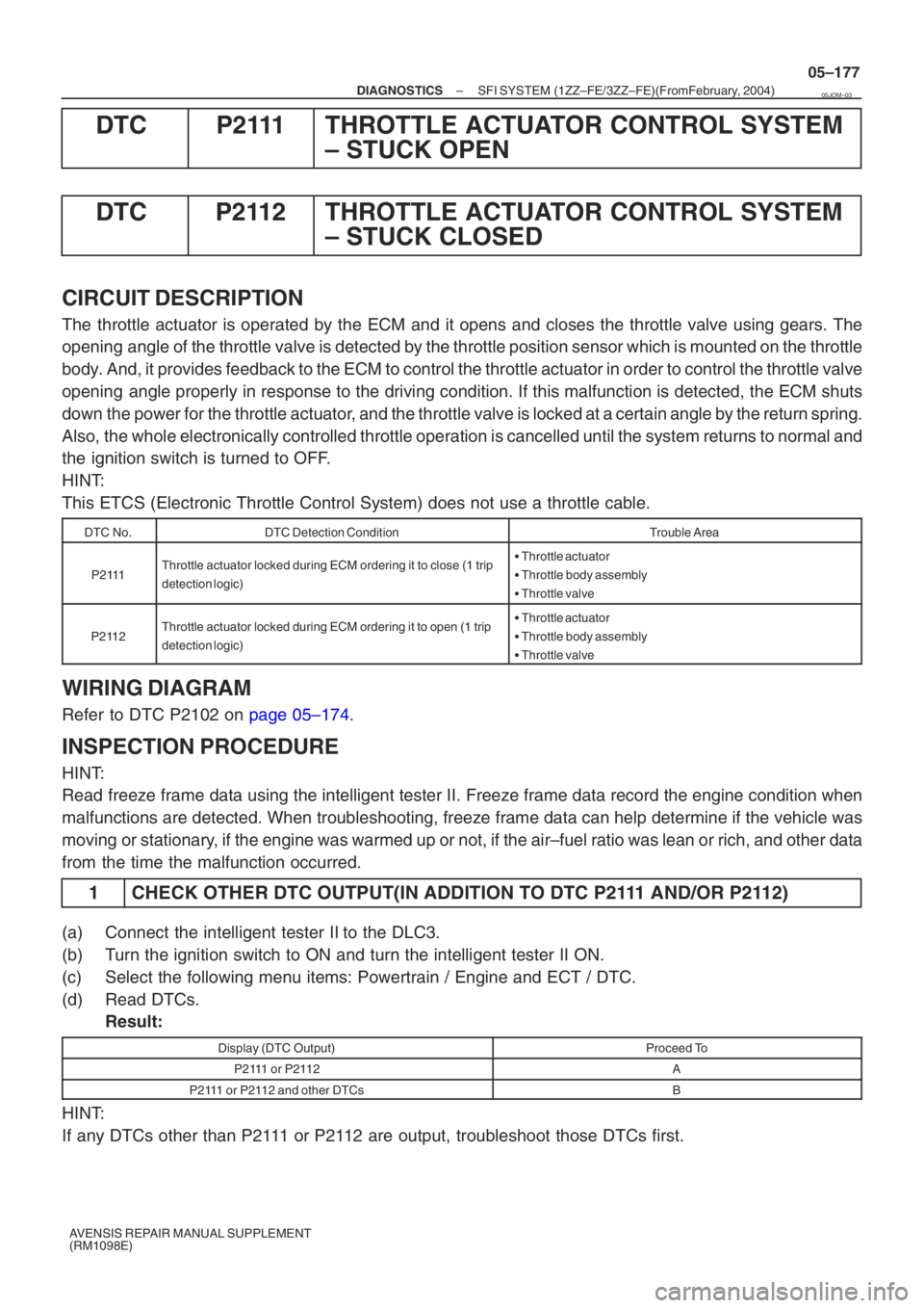
CIRCUIT DESCRIPTION
The throttle actuator is operated by the ECM and it opens and closes the thr\
ottle valve using gears. The
opening angle of the throttle valve is detected by the throttle position sensor which is mounted on the throttl\
e
body. And, it provides feedback to the ECM to control the throttle actuator \
in order to control the throttle valve
opening angle properly in response to the driving condition. If this malfunctio\
n is detected, the ECM shuts
down the power for the throttle actuator, and the throttle valve is locked at a certain angle by the return spring.
Also, the whole electronically controlled throttle operation is cancelled until th\
e system returns to normal and
the ignition switch is turned to OFF.
HINT:
This ETCS (Electronic Throttle Control System) does not use a throttle\
cable.
DTC No.DTC Detection ConditionTrouble Area
P2111Throttle actuator locked during ECM ordering it to close (1 trip
detection logic)� Throttle actuator
� Throttle body assembly
� Throttle valve
P2112Throttle actuator locked during ECM ordering it to open (1 trip
detection logic)�Throttle actuator
� Throttle body assembly
� Throttle valve
WIRING DIAGRAM
Refer to DTC P2102 on page 05–174.
INSPECTION PROCEDURE
HINT:
Read freeze frame data using the intelligent tester II. Freeze frame data record the engine condition\
when
malfunctions are detected. When troubleshooting, freeze frame data can h\
elp determine if the vehicle was
moving or stationary, if the engine was warmed up or not, if the air–fuel ratio was lean \
or rich, and other data
from the time the malfunction occurred.
1 CHECK OTHER DTC OUTPUT(IN ADDITION TO DTC P2111 AND/OR P2112)
(a) Connect the intelligent tester II to the DLC3.
(b) Turn the ignition switch to ON and turn the intelligent tester II ON.
(c) Select the following menu items: Powertrain / Engine and ECT / DTC.
(d) Read DTCs. Result:
Display (DTC Output)Proceed To
P2111 or P2112A
P2111 or P2112 and other DTCsB
HINT:
If any DTCs other than P2111 or P2112 are output, troubleshoot those DTCs first.
05JOM–03
Page 4954 of 5135

A93656
ECM
STA E1312
B–Y
IJW–BJ12 BB J13J/C W–B 1 5
32 1AM2 2
B–G
B–R1
S51S4
Starter
Battery7
IK1
FL MAIN 4B 4A
Engine Room
J/B No. 4
BB 55
5 1
11A
B–GB–R
IE41
(LHD)IP11
(RHD)B–R
Engine
Room
R/B No. 1
Engine
Room
J/B No.1
Driver
Side R/BST
Relay
2DJ
9DA Driver
Side J/B B–R
B–RI13
Ignition Switch
4 5 B–Y
B–Y
6
2ST 1
6 Fuse
Block
B–WB–YB–Y
J12 AC J13
A J12 1
1
(M/T)
B–W
(A/T)
N1
Neutral Start Switch96B–Y
(A/T)E1 E13
EH BR
55
– DIAGNOSTICSSFI SYSTEM (1ZZ–FE/3ZZ–FE)(From February, 2004)
05–171
AVENSIS REPAIR MANUAL SUPPLEMENT
(RM1098E)
DTC P0617 STARTER RELAY CIRCUIT HIGH
CIRCUIT DESCRIPTION
While the engine is being cranked, the positive battery voltage is applied to terminal STA of the ECM.
DTC No.DTC Detection ConditionTrouble Area
P0617
When conditions (a), (b) and (c) are met when the battery volt-
age of 10.5 V or more is applied for 20 seconds
(a) Vehicle speed greater than 20 km/h (12 mph)
(b) Engine RPM greater than 1,000 rpm
(c) STA signal ON�Short in park/neutral position switch circuit (MMT)
�Short in STA circuit
�Park/neutral position switch (MMT)
�ECM
WIRING DIAGRAM
05KOC–02
Page 4955 of 5135

05–172
–
DIAGNOSTICS SFI SYSTEM (1ZZ–FE/3ZZ–FE)(From February, 2004)
AVENSIS REPAIR MANUAL SUPPLEMENT
(RM1098E)
INSPECTION PROCEDURE
HINT:
Read freeze frame data using the intelligent tester II. Freeze frame data record the engine condition\
when
malfunctions are detected. When troubleshooting, freeze frame data can h\
elp determine if the vehicle was
moving or stationary, if the engine was warmed up or not, if the air–fuel ratio was lean \
or rich, and other data
from the time the malfunction occurred.
1 READ VALUE OF INTELLIGENT TESTER II(STA SIGNAL)
(a) Connect the intelligent tester ll to the DLC3.
(b) Turn the ignition switch to ON and turn the intelligent tester ll ON.
(c) Select the following menu items: Powertrain / Engine and ECT / Data List\
/ Starter SIG.
(d) Check the result when the ignition switch is turned to the ON and START positions. Standard:
Ignition Switch PositionONSTART
STARTER SIGOFFON
OK PROCEED TO NEXT CIRCUIT INSPECTION SHOWN ON PROBLEM SYMPTOMS TABLE
(See page 05–12 )
NG
Page 4957 of 5135

05–170
– DIAGNOSTICSSFI SYSTEM (1ZZ–FE/3ZZ–FE)(From February, 2004)
AVENSIS REPAIR MANUAL SUPPLEMENT
(RM1098E)
DTC P0604 INTERNAL CONTROL MODULE RANDOM
ACCESS MEMORY (RAM) ERROR
DTC P0606 ECM/PCM PROCESSOR
DTC P0607 CONTROL MODULE PERFORMANCE
DTC P0657 ACTUATOR SUPPLY VOLTAGE
CIRCUIT/OPEN
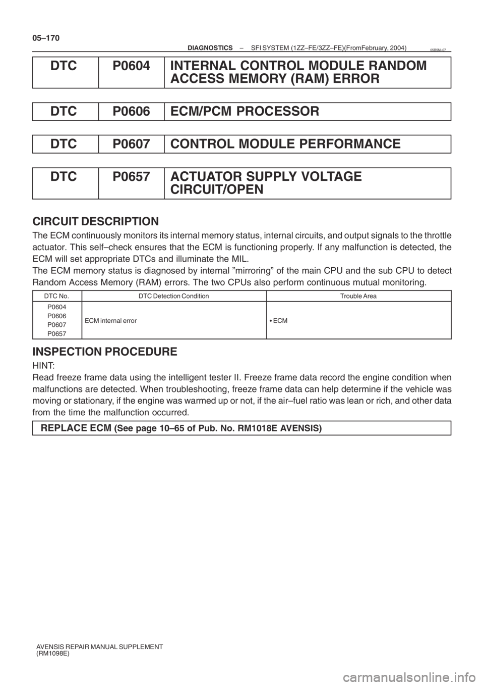
CIRCUIT DESCRIPTION
The ECM continuously monitors its internal memory status, internal circuits, and output signals to the throttle
actuator. This self–check ensures that the ECM is functioning properly. If any malfunction is detected, the
ECM will set appropriate DTCs and illuminate the MIL.
The ECM memory status is diagnosed by internal ”mirroring” of the main CPU and the sub CPU to detect
Random Access Memory (RAM) errors. The two CPUs also perform continuous mutual monitoring.
DTC No.DTC Detection ConditionTrouble Area
P0604
P0606
P0607
P0657
ECM internal error�ECM
INSPECTION PROCEDURE
HINT:
Read freeze frame data using the intelligent tester II. Freeze frame data record the engine condition when
malfunctions are detected. When troubleshooting, freeze frame data can help determine if the vehicle was
moving or stationary, if the engine was warmed up or not, if the air–fuel ratio was lean or rich, and other data
from the time the malfunction occurred.
REPLACE ECM (See page 10–65 of Pub. No. RM1018E AVENSIS)
05B5M–07
Page 4958 of 5135
A79413
From
Speed SensorSkid
Control
ECU4–Pulse
Combination
Meter4–Pulse
ECM 05–158
– DIAGNOSTICSSFI SYSTEM (1ZZ–FE/3ZZ–FE)(From February, 2004)
AVENSIS REPAIR MANUAL SUPPLEMENT
(RM1098E)
DTC P0500 VEHICLE SPEED SENSOR ”A”
CIRCUIT DESCRIPTION
The speed sensor detects the wheel speed and sends appropriate signals to the skid control ECU. The skid
control ECU converts these wheel speed signals into a 4–pulse signal and outputs it to the ECM via the com-
bination meter. The ECM determines the vehicle speed based on the frequency of these pulse signals.
DTC No.DTC Detection ConditionTrouble Area
P0500
Conditions (a), (b) and (c) continue for 8 seconds or more
(2 trip detection logic):
(a) Engine coolant temperature is more than 60�C (140�F)
(b) Engine speed is between 2,000 rpm and 3,000 rpm
(c) No speed signal is input to ECM�Open or short in speed sensor circuit
�Speed sensor
�Combination meter
�ECM
�Skid control ECU
05B5L–14