Page 5014 of 5135
C52361
DLC3:CG
TC
I41985
Normal System Code: Diagnosis Trouble Code:
0.25 sec.
0.25 sec.
ON
OFF ON
OFF 0.5 sec.
0.5 sec. 1.5 sec. 2.5 sec.
4.5 sec.
Code 21 Code 52
05–308
–
DIAGNOSTICS CRUISE CONTROL SYSTEM (2AZ–FSE)(From
February, 2004)
AVENSIS REPAIR MANUAL SUPPLEMENT
(RM1098E)
(d) Output DTCs using diagnosis check wire. (1) Using SST, create a short–circuit between terminalsTC and CG of the DLC3.
(2) Turn the ignition switch to the ON position.
(3) Read and record DTCs from the CRUISE main indi- cator light on the combination meter. As examples,
refer to the chart below for the blinking patterns of
the normal system code and diagnosis trouble code
21 and 52.
HINT:
If the CRUISE main indicator light does not blink because of any
DTC or in the normal code blinking pattern, inspect the following
circuits.
Relevant CircuitSee Page
Diagnosis circuit05–328
CRUISE main indicator circuit05–327
Page 5019 of 5135
05ADI–06
–
DIAGNOSTICS CRUISE CONTROL SYSTEM (2AZ–FSE)(From
February, 2004)05–303
AVENSIS REPAIR MANUAL SUPPLEMENT
(RM1098E)
CRUISE CONTROL SYSTEM (2AZ–FSE)(From February,
2004)
HOW TO PROCEED WITH TROUBLESHOOTING
1 VEHICLE BROUGHT TO WORKSHOP
2 CUS TOMER PROBLEM ANA LYSIS ( SEE PAGE 05–305 )
3 CHECK AND CLEAR DTCS ( SEE PAGE 05–306 )
4 PROBLEM SYMPTOM CONFIRMATION
SYMPTOM DOES NOT OCCUR (GO TO STEP 5)
SYMPTOM OCCURS (GO TO STEP 6)
5 SYMP TOM SIMUL ATION ( SEE PAGE 01–22 )
6 DTC CHECK ( SEE PAGE 05–306 )
(a) Check for cruise control system DTC output.
TROUBLE CODE (GO TO STEP 7)
NORMAL SYSTEM CODE (GO TO STEP 8)
7 DTC CHART ( SEE PAGE 05–313 )
8 PROBLEM SYMPTOMS TABLE ( SEE PAGE 05–316 )
9 CIRCUIT INSPECTION ( SEE PAGE 05–317 T O 05–328 )
Page 5021 of 5135

G25416
ECM
E10
K2
Kick Down SW
IP 6
6
CA 12
CJ
IG24
W–B Center J/B
31
8
IG2
W–B W
W
W–BKD *1
*1: LHD
G26420
Wire Harness Side:
(Connector Front View):
K2
–
DIAGNOSTICS ELECTRONIC CONTROLLED AUTOMATIC
TRANSAXLE [ECT] (U341E) (From February, 2004)05–301
AVENSIS REPAIR MANUAL SUPPLEMENT
(RM1098E)
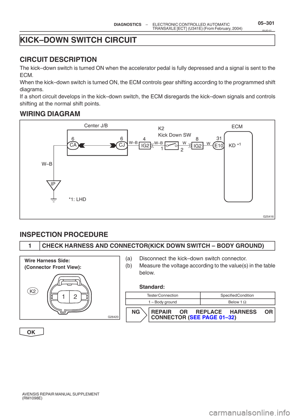
KICK–DOWN SWITCH CIRCUIT
CIRCUIT DESCRIPTION
The kick–down switch is turned ON when the accelerator pedal is fully de\
pressed and a signal is sent to the
ECM.
When the kick–down switch is turned ON, the ECM controls gear shiftin\
g according to the programmed shift
diagrams.
If a short circuit develops in the kick–down switch, the ECM disregards\
the kick–down signals and controls
shifting at the normal shift points.
WIRING DIAGRAM
INSPECTION PROCEDURE
1 CHECK HARNESS AND CONNECTOR(KICK DOWN SWITCH – BODY GROUND)
(a) Disconnect the kick–down switch connector.
(b) Measure the voltage according to the value(s) in the table
below.
Standard:
Tester ConnectionSpecified Condition
1 – Body groundBelow 1 Ω
NG REPAIR OR REPLACE HARNESS OR
CONNEC TOR ( SEE PAGE 01–32 )
OK
05L2O–01
Page 5022 of 5135
![TOYOTA AVENSIS 2005 Service Repair Manual G26835
1
2
K2
Switch Side:
(Connector Front View):
�
�\f
�
�\f
H42587KD
ECM: E13
E12E10E9
05–302–
DIAGNOSTICS ELECTRONIC CONTROLLED AUTOMATIC
TRANSAXLE [ECT] (U341E) (From February, 2004)
AVEN TOYOTA AVENSIS 2005 Service Repair Manual G26835
1
2
K2
Switch Side:
(Connector Front View):
�
�\f
�
�\f
H42587KD
ECM: E13
E12E10E9
05–302–
DIAGNOSTICS ELECTRONIC CONTROLLED AUTOMATIC
TRANSAXLE [ECT] (U341E) (From February, 2004)
AVEN](/manual-img/14/57441/w960_57441-5021.png)
G26835
1
2
K2
Switch Side:
(Connector Front View):
�
�\f
�
�\f
H42587KD
ECM: E13
E12E10E9
05–302–
DIAGNOSTICS ELECTRONIC CONTROLLED AUTOMATIC
TRANSAXLE [ECT] (U341E) (From February, 2004)
AVENSIS REPAIR MANUAL SUPPLEMENT
(RM1098E)
2 INSPECT KICK DOWN SWITCH
(a) Measure resistance according to the value(s) in the table below when kick–down switch is ON and OFF.
Standard:
Switch ConditionTester ConnectionSpecified Condition
Press continuously
(Kick–down switch is ON)1 – 2Below 1 Ω
Release
(Kick–down switch is OFF)
↑10 kΩ or higher
NG REPLACE KICK DOWN SWITCH
OK
3 CHECK HARNESS AND CONNECTOR(KICK DOWN SWITCH – ECM)
(a) Connect the kick–down switch connector.
(b) Disconnect the ECM connector.
(c) Measure resistance according to the value(s) in the table below when accelerator pedal is fully depressed or not.
Standard:
Switch ConditionTester ConnectionSpecified Condition
Fully depressed
(Kick–down switch is ON)E10 –31 (KD) –
Body groundBelow 1 Ω
Release
(Kick–down switch is OFF)
↑10 kΩ or higher
NG REPAIR OR REPLACE HARNESS OR
CONNEC TOR ( SEE PAGE 01–32 )
OK
PROCEED TO NEXT CIRCUIT INSPECTION SHOWN IN PROBLEM SYMPTOMS TABLE
( SEE PAGE 05–229 )
Page 5023 of 5135

D30688
ECM
MPX2
MPX1 29
18 E10 11
B8
22 SNOWI14
Integration Relay
8 14
DA B E8
ECT Pattern Select SW
*1: RHD
*2: LHD 4 1 W–B
CH
CF
CA 8
11
6
W–B
IPE10 MPX1
MPX2
*1
*2
B8
(*3) Pattern Select Switch (ECT SNOW Switch)
When the ECT SNOW switch is pushed, the switch contact is made and the ECT SNOW mode is selected.
To cancel the ECT SNOW mode, push the ECT SNOW switch once again. The ECT SNOW mode is automatical-
ly cancelledout when the ignition switch is turned ”OFF”.
*3
Instrument Panel J/B
– DIAGNOSTICSELECTRONIC CONTROLLED AUTOMATIC
TRANSAXLE [ECT] (U341E) (From February, 2004)05–297
AVENSIS REPAIR MANUAL SUPPLEMENT
(RM1098E)
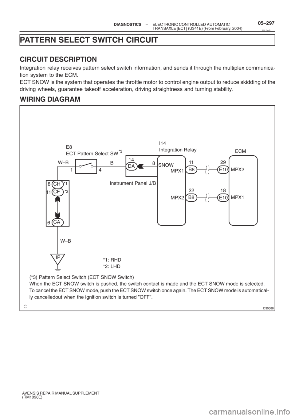
PATTERN SELECT SWITCH CIRCUIT
CIRCUIT DESCRIPTION
Integration relay receives pattern select switch information, and sends it through the multiplex communica-
tion system to the ECM.
ECT SNOW is the system that operates the throttle motor to control engine output to reduce skidding of the
driving wheels, guarantee takeoff acceleration, driving straightness and turning stability.
WIRING DIAGRAM
05L2N–01
Page 5024 of 5135
![TOYOTA AVENSIS 2005 Service Repair Manual B59192
Wire Harness Side:
(Connector Front View):E8
05–298–
DIAGNOSTICS ELECTRONIC CONTROLLED AUTOMATIC
TRANSAXLE [ECT] (U341E) (From February, 2004)
AVENSIS REPAIR MANUAL SUPPLEMENT
(RM1098E)
I TOYOTA AVENSIS 2005 Service Repair Manual B59192
Wire Harness Side:
(Connector Front View):E8
05–298–
DIAGNOSTICS ELECTRONIC CONTROLLED AUTOMATIC
TRANSAXLE [ECT] (U341E) (From February, 2004)
AVENSIS REPAIR MANUAL SUPPLEMENT
(RM1098E)
I](/manual-img/14/57441/w960_57441-5023.png)
B59192
Wire Harness Side:
(Connector Front View):E8
05–298–
DIAGNOSTICS ELECTRONIC CONTROLLED AUTOMATIC
TRANSAXLE [ECT] (U341E) (From February, 2004)
AVENSIS REPAIR MANUAL SUPPLEMENT
(RM1098E)
INSPECTION PROCEDURE
1 DRIVING TEST
(a) Start the engine.
(b) Turn the ECT SNOW switch ”OFF” (Normal drive mode).
(c) Confirm vehicle response by driving from a parked position to fully depressing the accelerator pe\
dal.
(d) Turn the ECT SNOW switch ”ON” and perform the same check as (c). Confirm that there is a difference between ECT SNOW switch ”ON” and ”OFF”.
HINT:
�Driving test should be done on a paved road (a nonskid road).
�Make sure not to use the TRAC system when testing a vehicle equipped wit\
h one.
OK:
There is a difference in acceleration between ”ON” and ”OFF”\
.
NG Go to step 2
OK
PROCEED TO NEXT CIRCUIT INSPECTION SHOWN IN PROBLEM SYMP TOMS TABLE
( SEE PAGE 05–229 )
2 CHECK HARNESS AND CONNECTOR(PATTERN SELECT SWITCH ASSY NO.1 –
BODY GROUND)
(a) Disconnect the connector of pattern select switch.
(b) Measure the resistance according to the value(s) in the
table below.
Standard:
Tester ConnectionSpecified Condition
1 – Body groundBelow 1 Ω
NG REPAIR OR REPLACE HARNESS OR
CONNEC TOR ( SEE PAGE 01–32 )
OK
Page 5026 of 5135
D30751
Instrument Panel J/B AssyVehicle Front Side:
DA
DA
SNOW
05–300–
DIAGNOSTICS ELECTRONIC CONTROLLED AUTOMATIC
TRANSAXLE [ECT] (U341E) (From February, 2004)
AVENSIS REPAIR MANUAL SUPPLEMENT
(RM1098E)
4 CHECK HARNESS AND CONNECTOR(PATTERN SELECT SWITCH ASSY NO.1 – MULTIPLEX NETWORK BODY ECU)
(a) Connect the connector of pattern select switch.
(b) Disconnect the instrument panel J/B assy (integration
relay) connector.
(c) Measure the resistance between terminal SNOW of instrument panel J/B assy (integration relay) connector
and body ground.
Standard:
Switch ConditionTester ConnectionSpecified Condition
Press continuously
Pattern select switch (SNOW)DA – 14 (SNOW) –
Body groundBelow 1 Ω
Release
Pattern select switch (SNOW)
↑10 kΩ or higher
NG REPAIR OR REPLACE HARNESS OR
CONNEC TOR ( SEE PAGE 01–32 )
OK
PROCEED TO NEXT CIRCUIT INSPECTION SHOWN IN PROBLEM SYMPTOMS TABLE
( SEE PAGE 05–229 )
Page 5027 of 5135
![TOYOTA AVENSIS 2005 Service Repair Manual G31165
E1
Electronically Controlled
Transmission Solenoid
R
E12SLECM
15
LG
4
SL+B
CPU
– DIAGNOSTICSELECTRONIC CONTROLLED AUTOMATIC
TRANSAXLE [ECT] (U341E) (From February, 2004)05–289
AVENSIS REPAI TOYOTA AVENSIS 2005 Service Repair Manual G31165
E1
Electronically Controlled
Transmission Solenoid
R
E12SLECM
15
LG
4
SL+B
CPU
– DIAGNOSTICSELECTRONIC CONTROLLED AUTOMATIC
TRANSAXLE [ECT] (U341E) (From February, 2004)05–289
AVENSIS REPAI](/manual-img/14/57441/w960_57441-5026.png)
G31165
E1
Electronically Controlled
Transmission Solenoid
R
E12SLECM
15
LG
4
SL+B
CPU
– DIAGNOSTICSELECTRONIC CONTROLLED AUTOMATIC
TRANSAXLE [ECT] (U341E) (From February, 2004)05–289
AVENSIS REPAIR MANUAL SUPPLEMENT
(RM1098E)
DTC P2769 TORQUE CONVERTER CLUTCH SOLENOID
CIRCUIT LOW (SHIFT SOLENOID VALVE SL)
DTC P2770 TORQUE CONVERTER CLUTCH SOLENOID
CIRCUIT HIGH (SHIFT SOLENOID VALVE SL)
CIRCUIT DESCRIPTION
The shift solenoid valve SL is turned ”ON” and ”OFF” by signals from the ECM in order to control the hydraulic
pressure operation, the lock–up relay valve, which then the controls operation of the lock–up clutch.
DTC No.DTC Detection ConditionTrouble Area
P2769ECM detects short in solenoid valve SL circuit (0.1 sec.) when
solenoid valve SL is operated (2–trip detection logic)�Short in shift solenoid valve SL circuit
�Shift solenoid valve SL
�ECM
P2770ECM detects open in solenoid valve SL circuit (0.1 sec.) when
solenoid valve SL is not operated (2–trip detection logic)�Open in shift solenoid valve SL circuit
�Shift solenoid valve SL
�ECM
MONITOR DESCRIPTION
Based on the signals from the Throttle Position Sensor, the Airflow Meter and the Crankshaft Position Sen-
sor, the ECM sends a signal to the shift solenoid valve SL to regulate the hydraulic pressure and provide
smoother gearshifts. The shift solenoid valve SL responds to commands from the ECM. The valve controls
the lock–up relay valve to perform the torque–converter lock–up function. If the ECM detects an open or
short circuit for shift solenoid valve SL, it will illuminate the MIL.
WIRING DIAGRAM
05CW7–06