Page 4851 of 5135
C91931
Valve Body Oil
Strainer Assy
C91932
O−ring
C91933
C83127
C83128
− AUTOMATIC TRANSMISSION / TRANSAUTOMATIC TRANSAXLE ASSY (U151E/U151F)
40−21
U151E, U151F A/T REPAIR MANUAL (RM1021U)
13. REMOVE VALVE BODY OIL STRAINER ASSY
(a) Remove the 3 bolts and oil strainer.
(b) Remove the O−ring from the oil strainer.
14. REMOVE TRANSMISSION VALVE BODY ASSY
(a) Support the valve body assy and remove the 17 bolts and
valve body assy.
15. REMOVE GOVERNOR APPLY GASKET NO.1
(a) Remove the governor apply gasket No.1 from the trans-
axle case.
16. REMOVE TRANSAXLE CASE 2ND BRAKE GASKET
(a) Remove the transaxle case 2nd brake gasket from the
transaxle case.
Page 4852 of 5135
C83129
D03554
Check Ball
D03555
D03556
D03902
O−ring
C−3 Accumulator Piston 40−22
− AUTOMATIC TRANSMISSION / TRANSAUTOMATIC TRANSAXLE ASSY (U151E/U151F)
U151E, U151F A/T REPAIR MANUAL (RM1021U)
17. REMOVE BRAKE DRUM GASKET
(a) Remove the brake drum gasket from the transaxle case.
18. REMOVE CHECK BALL BODY
(a) Remove the check ball body and spring from the trans-
axle case.
19. REMOVE C−3 ACCUMULATOR PISTON
(a) Remove the spring from the C−3 accumulator piston.
(b) Apply compressed air (392 kPa, 4.0 kgf/cm
2, 57 psi) to the
oil hole and remove the C−3 accumulator piston.
NOTICE:
SBlowing off the air may cause the piston to jump−out.
When removing the piston, hold it by your hand using
a waste cloth.
STake care not to splash ATF when air−blowing.
(c) Remove the O−ring from the C−3 accumulator piston.
Page 4853 of 5135

D26401
D26402
O−ring
O−ring Reverse clutch Accumulator Piston
D03558
D03904
O−ring
B−3 Accumulator Piston
D03559
− AUTOMATIC TRANSMISSION / TRANSAUTOMATIC TRANSAXLE ASSY (U151E/U151F)
40−23
U151E, U151F A/T REPAIR MANUAL (RM1021U)
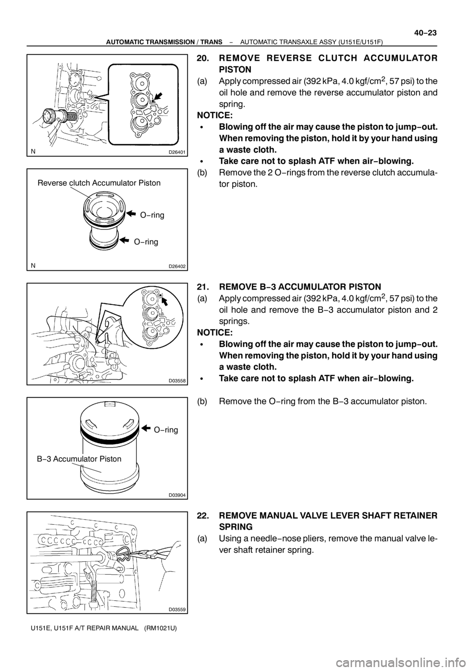
20. REMOVE REVERSE CLUTCH ACCUMULATOR
PISTON
(a) Apply compressed air (392 kPa, 4.0 kgf/cm
2, 57 psi) to the
oil hole and remove the reverse accumulator piston and
spring.
NOTICE:
SBlowing off the air may cause the piston to jump−out.
When removing the piston, hold it by your hand using
a waste cloth.
STake care not to splash ATF when air−blowing.
(b) Remove the 2 O−rings from the reverse clutch accumula-
tor piston.
21. REMOVE B−3 ACCUMULATOR PISTON
(a) Apply compressed air (392 kPa, 4.0 kgf/cm
2, 57 psi) to the
oil hole and remove the B−3 accumulator piston and 2
springs.
NOTICE:
SBlowing off the air may cause the piston to jump−out.
When removing the piston, hold it by your hand using
a waste cloth.
STake care not to splash ATF when air−blowing.
(b) Remove the O−ring from the B−3 accumulator piston.
22. REMOVE MANUAL VALVE LEVER SHAFT RETAINER
SPRING
(a) Using a needle−nose pliers, remove the manual valve le-
ver shaft retainer spring.
Page 4855 of 5135
D26382
Parking Lock Rod Sub−assy
D03566
D08046Oil Pump Assy
− AUTOMATIC TRANSMISSION / TRANSAUTOMATIC TRANSAXLE ASSY (U151E/U151F)
40−25
U151E, U151F A/T REPAIR MANUAL (RM1021U)
26. REMOVE PARKING LOCK ROD SUB−ASSY
(a) Remove the parking lock rod from the manual valve lever.
27. REMOVE MANUAL VALVE LEVER SHAFT OIL SEAL
(a) Using a screwdriver, remove the oil seal from the trans-
axle case.
28. FIX AUTOMATIC TRANSAXLE ASSY
(a) Fix the transaxle case with the oil pump side facing up.
29. INSPECT INPUT SHAFT ENDPLAY
(a) Using a dial indicator, measure the input shaft endplay.
Endplay: 0.262−1.244 mm (0.01−0.049 in.)
Page 4856 of 5135

D25608
U151E:
U151F:
D03569
Oil Pump Assy
D25505
Thrust Needle
Roller Bearing
Differential Gear Assy Forward Clutch Assy
D25506
Thrust Bearing Underdrive Race No.2
Differential
Gear Assy Forward Clutch Assy
Underdrive Planetary Gear Assy
40−26
− AUTOMATIC TRANSMISSION / TRANSAUTOMATIC TRANSAXLE ASSY (U151E/U151F)
U151E, U151F A/T REPAIR MANUAL (RM1021U)
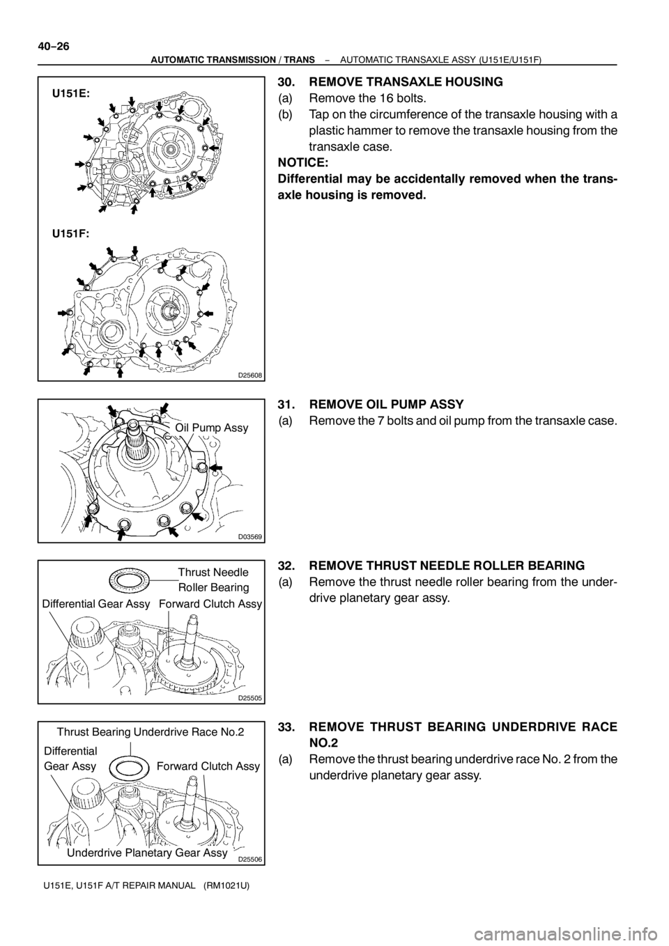
30. REMOVE TRANSAXLE HOUSING
(a) Remove the 16 bolts.
(b) Tap on the circumference of the transaxle housing with a
plastic hammer to remove the transaxle housing from the
transaxle case.
NOTICE:
Differential may be accidentally removed when the trans-
axle housing is removed.
31. REMOVE OIL PUMP ASSY
(a) Remove the 7 bolts and oil pump from the transaxle case.
32. REMOVE THRUST NEEDLE ROLLER BEARING
(a) Remove the thrust needle roller bearing from the under-
drive planetary gear assy.
33. REMOVE THRUST BEARING UNDERDRIVE RACE
NO.2
(a) Remove the thrust bearing underdrive race No. 2 from the
underdrive planetary gear assy.
Page 4861 of 5135
D26388
Rear Clutch
Oil Seal
Ring Outer
D26389
D26472
SST
D26390
D26391
Brake Apply Tube
Clutch Apply Tube
− AUTOMATIC TRANSMISSION / TRANSAUTOMATIC TRANSAXLE ASSY (U151E/U151F)
40−31
U151E, U151F A/T REPAIR MANUAL (RM1021U)
46. REMOVE TRANSAXLE CASE NO.1PLUG
(a) Remove the 4 transaxle case No.1 plugs from the trans-
axle rear cover.
(b) Remove the 4 O−rings from the 4 transaxle case No.1
plugs.
47. REMOVE REAR CLUTCH OIL SEAL RING OUTER
(a) Remove the 3 rear clutch oil seal rings from the transaxle
rear cover.
48. REMOVE NEEDLE ROLLER BEARING
(a) Using SST, remove the needle−roller bearing from the
transaxle rear cover.
SST 09387−00041 (09387−01021, 09387−01030,
09387−01040)
49. REMOVE GOVERNOR APPLY GASKET NO.1
(a) Using a screwdriver, remove the 3 apply gaskets.
50. REMOVE BRAKE APPLY TUBE
(a) Remove the bolt, clamp and brake apply tube.
(b) Remove the clutch apply tube.
(c) Remove the brake apply tube from the clamp.
Page 4870 of 5135
D03605
SSTHold
Turn
D03914
Underdrive
Clutch Drum
Oil Seal Ring
D26383
D03606
SST
Hold
Turn
D03915
Underdrive
Output
Shaft Oil
Seal Ring
40−40
− AUTOMATIC TRANSMISSION / TRANSAUTOMATIC TRANSAXLE ASSY (U151E/U151F)
U151E, U151F A/T REPAIR MANUAL (RM1021U)
76. REMOVE NEEDLE ROLLER BEARING
(a) Using SST, remove the needle−roller bearing from the
transaxle case.
SST 09387−00041 (09387−01010, 09387−01030,
09387−01040)
77. REMOVE UNDERDRIVE CLUTCH DRUM OIL SEAL
RING
(a) Remove the 2 oil seal rings from the transaxle case.
78. REMOVE TRANSAXLE CASE NO.1PLUG
(a) Remove the 2 transaxle case No. 1 plugs.
(b) Remove the 2 O−rings from the 2 transaxle case No. 1
plugs.
79. REMOVE UNDERDRIVE CYLINDRICAL ROLLER
BEARING
(a) Using SST, remove the underdrive cylindrical roller bear-
ing from the transaxle case.
SST 09514−35011
80. REMOVE UNDERDRIVE OUTPUT SHAFT OIL SEAL
RING
(a) Remove the oil seal ring from the transaxle housing.
Page 4874 of 5135

D26400
Transaxle Apply
Tube Clamp
Differential Gear Lube Apply Tube
D26383
Underdrive
Output Shaft
Oil Seal Ring
D03915
AT F
D03807
SST
D03914
Underdrive
Clutch Drum
Oil Seal Ring
AT F 40−44
− AUTOMATIC TRANSMISSION / TRANSAUTOMATIC TRANSAXLE ASSY (U151E/U151F)
U151E, U151F A/T REPAIR MANUAL (RM1021U)
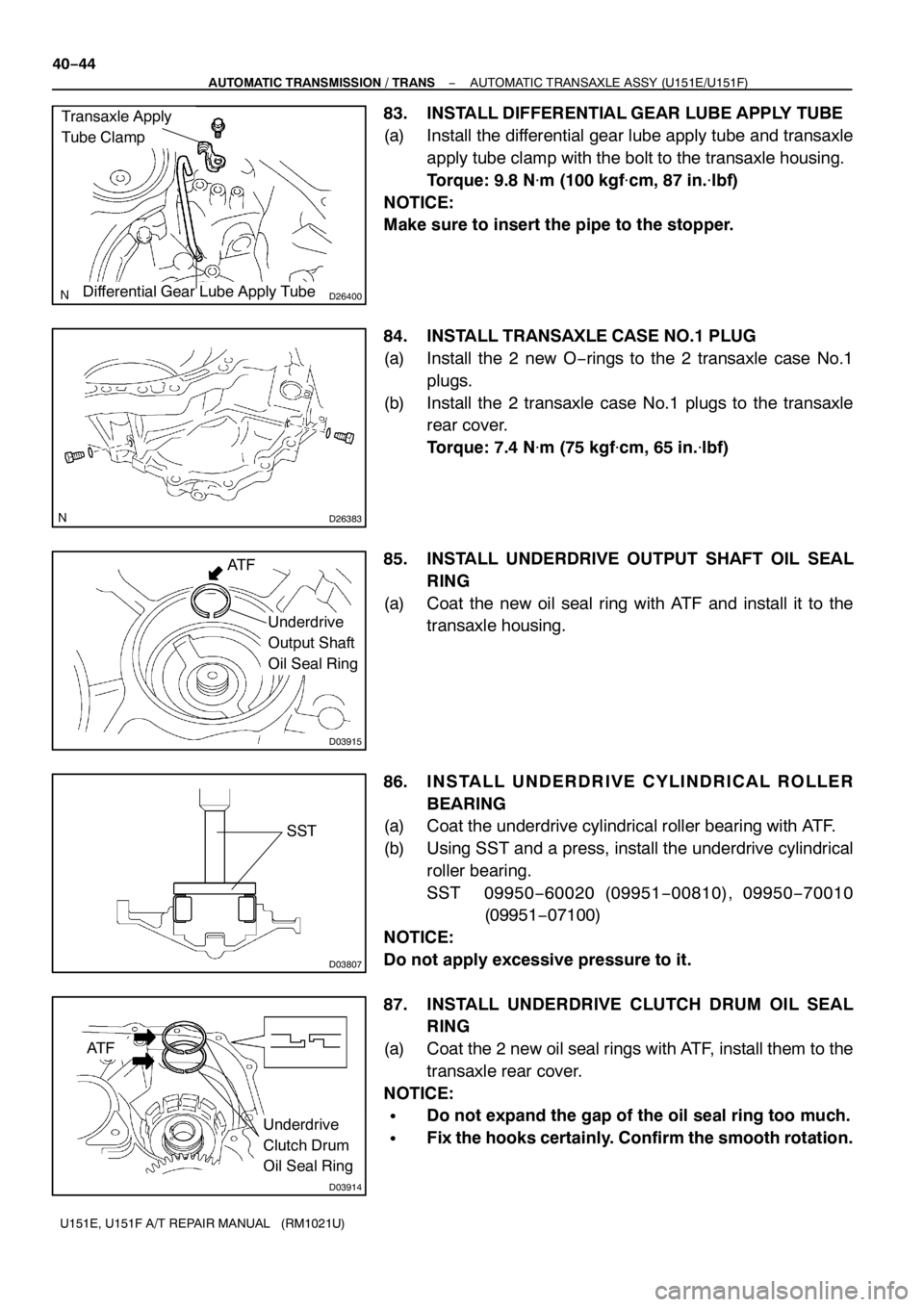
83. INSTALL DIFFERENTIAL GEAR LUBE APPLY TUBE
(a) Install the differential gear lube apply tube and transaxle
apply tube clamp with the bolt to the transaxle housing.
Torque: 9.8 N�m(100 kgf�cm, 87 in.�lbf)
NOTICE:
Make sure to insert the pipe to the stopper.
84. INSTALL TRANSAXLE CASE NO.1PLUG
(a) Install the 2 new O−rings to the 2 transaxle case No.1
plugs.
(b) Install the 2 transaxle case No.1 plugs to the transaxle
rear cover.
Torque: 7.4 N�m (75 kgf�cm, 65 in.�lbf)
85. INSTALL UNDERDRIVE OUTPUT SHAFT OIL SEAL
RING
(a) Coat the new oil seal ring with ATF and install it to the
transaxle housing.
86. INSTALL UNDERDRIVE CYLINDRICAL ROLLER
BEARING
(a) Coat the underdrive cylindrical roller bearing with ATF.
(b) Using SST and a press, install the underdrive cylindrical
roller bearing.
SST 09950−60020 (09951−00810), 09950−70010
(09951−07100)
NOTICE:
Do not apply excessive pressure to it.
87. INSTALL UNDERDRIVE CLUTCH DRUM OIL SEAL
RING
(a) Coat the 2 new oil seal rings with ATF, install them to the
transaxle rear cover.
NOTICE:
SDo not expand the gap of the oil seal ring too much.
SFix the hooks certainly. Confirm the smooth rotation.