Page 4763 of 5135

SST
A09582
B07973
Cut PositionPry
SST
A08528
SST
A09583
Angle
SensorInward
14
−178−
ENGINE MECHANICAL CRANKSHAFT SEAL (1CD−FTV)(From September,
2003)
AVENSIS Supplement (RM1045E)
21. SET NO. 1 CYLINDER TO TDC/COMPRESSION (See page 14 −138)
22. REMOVE TIMING CHAIN COVER PLATE (See page 14 −138)
23. REMOVE TIMING BELT (See page 14 −138)
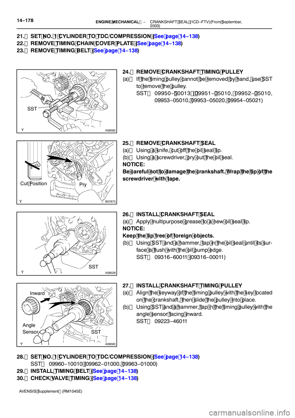
24. REMOVE CRANKSHAFT TIMING PULLEY
(a) If the timing pulley cannot be removed by hand, use SST to remove the pulley.
SST 09950 − 50013 ( 09951 − 05010, 09952 − 05010,
09953 −05010, 09953 −05020, 09954 −05021)
25. REMOVE CRANKSHAFT SEAL
(a) Using a knife, cut off the oil seal lip.
(b) Using a screwdriver, pry out the oil seal.
NOTICE:
Be careful not to damage the crankshaft. Wrap the tip of the
screwdriver with tape.
26. INSTALL CRANKSHAFT SEAL
(a) Apply multipurpose grease to a new oil seal lip.
NOTICE:
Keep the lip free of foreign objects.
(b) Using SST and a hammer, tap in the oil seal until its sur- face is flush with the oil pump edge.
SST 09316 −60011 (09316 −00011)
27. INSTALL CRANKSHAFT TIMING PULLEY
(a) Align the keyway of the timing pulley with the key located on the crankshaft, then slide the pulley into place.
(b) Using SST and a hammer, tap in the timing pulley with the
angle sensor facing inward.
SST 09223 −46011
28. SET NO. 1 CYLINDER TO TDC/COMPRESSION (See page 14 −138)
SST 09960 −10010 (09962 −01000, 09963 −01000)
29. INSTALL TIMING BELT (See page 14 −138)
30. CHECK VALVE TIMING (See page 14 −138)
Page 4764 of 5135

−
ENGINE MECHANICAL CRANKSHAFT SEAL (1CD−FTV)(From September,
2003)14 −179
AVENSIS Supplement (RM1045E)
31. INSTALL TIMING CHAIN COVER PLATE (See page 14 −138)
32. INSTALL TRANSVERSE ENGINE ENGINE MOUNTING BRACKET (See page 14 −138)
33. INSTALL TIMING BELT GUIDE (See page 14 −138)
34. INSTALL TIMING BELT NO.1 COVER (See page 14 −138)
35. INSTALL TIMING BELT NO.2 COVER (See page 14 −138)
36. INSTALL IDLER PULLEY SUB −ASSY (See page 14 −138)
37. INSTALL CRANKSHAFT PULLEY (See page 14 −138 )
SST 09213 −54015 (09213 −70020), 09330 −00021
38. INSTALL ENGINE MOUNTING INSULATOR SUB −ASSY RH (See page 14 −138)
39. INSTALL POWER STEERING IDLE PULLEY BRACKET (See page 14 −108)
40. ADJUST V (COOLER COMPRESSOR TO CRANKSHAFT PULLEY) BELT NO.1 (See Pub. No. RM1018E on page 14 −269)
41. INSTALL INJECTOR DRIVER (See page 14 −108)
42. INSTALL ENGINE COVER NO.1 (See page 14 −90)
43. INSTALL FRONT WHEEL RH
Torque: 103 N �m (1,050 kgf �cm, 76 ft �lbf)
44. ADD ENGINE OIL
45. CHECK FOR ENGINE OIL LEAKS
Page 4766 of 5135

I35328
(1)(2)
(3)
(4)
−
HEATER & AIR CONDITIONER W/PULLEY COMPRESSOR ASSY (2AZ −FSE)
55 −5
AVENSIS Supplement (RM1045E)
9. INSPECT COMPRESSOR OIL
(a) When replacing the w/pulley compressor assy with a new one, after gradually removing the refrigerant
gas from the service valve, drain the following amount of oil from the new w/pulley compressor assy
before installation.
Standard:
(Oil capacity inside new w/pulley compressor assy: 90 + 15 cc (3.0 + 0.5 fl. oz.) ) − (Remaining
oil amount in the removed w/pulley compressor assy) = (Oil amount to be removed when replac-
ing)
NOTICE:
S When checking the compressor oil level, observe the precautions on the cooler removal/instal-
lation.
S Since compressor oil remains in the pipes of the vehicle, if a new w/pulley compressor assy
is installed without removing some oil inside, the oil amount becomes excessive, preventing
heat exchange in the refrigerant cycle and causing refrigerant failure.
S If the remaining oil in the removed w/pulley compressor assy is too small in volume, check for
oil leakage.
S Be sure to use ND −OIL 8 for compressor oil.
10. INSTALL W/PULLEY COMPRESSOR ASSY
(a) Install the w/pulley compressor assy with the 4 bolts.
Torque: 29 N �m (300 kgf �cm, 2 1 ft �lbf)
NOTICE:
Tighten the bolts in the order shown in the illustration to
install the w/pulley compressor assy.
(b) Connect the connector.
11 . INSTALL FAN AND GENERATOR V BELT (See page 14− 5)
SST 09249 −63010
12. INSTALL COOLER REFRIGERANT DISCHARGE
HOSE NO. 1
(a) Remove the attached vinyl tape from the hose.
(b) Sufficiently apply compressor oil to a new O −ring and the
fitting surface of the w/pulley compressor assy.
Compressor oil: ND −OIL 8 or equivalent
(c) Install the O −ring on the cooler refrigerant discharge hose
No.1.
Page 4767 of 5135

I35327
I35326
55−6
− HEATER & AIR CONDITIONERW/PULLEY COMPRESSOR ASSY (2AZ−FSE)
AVENSIS Supplement (RM1045E)
(d) Install the cooler refrigerant discharge hose No.1 on the
w/pulley compressor assy with the bolt.
Torque: 9.8 N�m(100 kgf�cm, 87 in.�lbf)
13. INSTALL COOLER REFRIGERANT SUCTION HOSE
NO.1
(a) Remove the attached vinyl tape from the hose.
(b) Sufficiently apply compressor oil to a new O−ring and the
fitting surface of the w/pulley compressor assy.
Compressor oil: ND−OIL 8 or equivalent
(c) Install the O−ring on the cooler refrigerant suction hose
No.1.
(d) Install the cooler refrigerant suction hose No.1 on the w/
pulley compressor assy with the bolt.
Torque: 9.8 N�m(100 kgf�cm, 87 in.�lbf)
14. CHARGE REFRIGERANT (See Pub. No. RM1018E, page 55−38)
SST 07110−58060 (07117−58060, 07117−58070, 07117−58080, 07117−58090, 07117−78050,
07117−88060, 07117−88070, 07117−88080)
Specified amount: 440�á30 g (15.51�á1.06 oz.)
15. WARM UP ENGINE (See Pub. No. RM1018E, page 55−38)
16. INSPECT LEAKAGE OF REFRIGERANT (See Pub. No. RM1018E, page 55−38)
Page 4768 of 5135
4018A−01
D31327
D31328
D31328
D31327
40 −26
−
AUTOMATIC TRANSMISSION / TRANS TRANSMISSION OIL COOLER (U151E)
AVENSIS Supplement (RM1045E)
TRANSMISSION OIL COOLER (U 151E)
REPLACEMENT
1. DRAIN AUTOMATIC TRANSAXLE FLUID (SEE PUB. NO. RM 1018E, PAGE 40 −2)
2. DRAIN COOLANT (SEE PAGE 16− 7)
3. REMOVE TRANSMISSION OIL COOLER
(a) Loosen the clips and disconnect the 4 hoses from the transmission oil cooler.
(b) Remove the 3 bolts and the oil cooler from the bracket.
4. INSTALL TRANSMISSION OIL COOLER
(a) Install the oil cooler to the bracket with the 3 bolts. Torque: 12N �m( 122 kgf �cm, 9 ft �lbf)
(b) Connect the 4 hoses with the clips to the transmission.
Page 4769 of 5135
−
AUTOMATIC TRANSMISSION / TRANS TRANSMISSION OIL COOLER (U151E)
40−27
AVENSIS Supplement (RM1045E)
5. ADD COOLANT (SEE PAGE 16− 7)
6. ADD AUTOMATIC TRANSAXLE FLUID (SEE PUB. NO. RM 1018E, PAGE 40 −2)
7. INSPECT AUTOMATIC TRANSAXLE FLUID (SEE PUB. NO. RM 1018E, PAGE 40 −2)
Page 4770 of 5135

40189−01
D25831
SST
D25832
SST
D25833
SST
40 −24
−
AUTOMATIC TRANSMISSION / TRANS FRONT DIFFERENTIAL OIL SEAL (U151E)
AVENSIS Supplement (RM1045E)
FRONT DIFFERENTIAL OIL SEAL (U 151E)
REPLACEMENT
1. REMOVE FRONT WHEELS
2. REMOVE ENGINE UNDER COVER RH
3. REMOVE ENGINE UNDER COVER LH
4. DRAIN AUTOMATIC TRANSAXLE FLUID
(a) Remove the drain plug and gasket, and drain ATF.
(b) Install a new gasket and the drain plug. Torque: 47 N �m (480 kgf �cm, 35 ft �lbf)
5. REMOVE FRONT DRIVE SHAFT ASSY RH (SEE PAGE 30 −4)
6. REMOVE FRONT DRIVE SHAFT ASSY LH (SEE PAGE 30 −4)
7. REMOVE TRANSAXLE HOUSING OIL SEAL
(a) Using SST, pull out the oil seal. SST 09308 −00010
8. REMOVE DIFFERENTIAL SIDE BEARING RETAINER OIL SEAL
(a) Using SST, pull out the oil seal.
SST 09308 −00010
9. INSTALL TRANSAXLE HOUSING OIL SEAL
(a) Using SST and a hammer, drive in a new oil seal. SST 09316 −60011 (09316 −00011)
Oil seal drive in depth:
0 �á 0.5 mm (0 �á0.020 in.)
(b) Coat the lip of the oil seal with MP grease.
Page 4771 of 5135
D25834
SST
−
AUTOMATIC TRANSMISSION / TRANS FRONT DIFFERENTIAL OIL SEAL (U151E)
40−25
AVENSIS Supplement (RM1045E)
10. INSTALL DIFFERENTIAL SIDE BEARING RETAINER
OIL SEAL
(a) Using SST and a hammer, drive in a new oil seal. SST 09649 −17010, 09950 −70010 (09951 −07150)
Oil seal drive in depth:
0 �á 0.5 mm (0 �á 0.020 in.)
(b) Coat the lip of the oil seal with MP grease.
11 . INSTALL FRONT DRIVE SHAFT ASSY LH (SEE PAGE 30 −4)
1 2. INSTALL FRONT DRIVE SHAFT ASSY RH (SEE PAGE 30 −4)
1 3. INSTALL FRONT WHEELS
Torque: 103 N �m( 1,050 kgf �cm, 76 ft �lbf)
1 4. ADD AUTOMATIC TRANSAXLE FLUID (SEE PUB. NO. RM 1018E, PAGE40 −2)
1 5. INSPECT AUTOMATIC TRANSAXLE FLUID (SEE PUB. NO. RM 1018E, PAGE40 −2)
1 6. CHECK ABS SPEED SENSOR SIGNAL
(a) ABS WITH EBD & BA &TRAC & VSC SYSTEM (SEE PUB, NO. RM1018E, PAGE 5 −756)