Page 4729 of 5135
F45361F46832
C80802
F46213
To Master
Cylinder Rear
To
Master
Cylinder
Front
To Rear Wheel
RH
To Front Wheel LH
To Front Wheel RH
To Rear Wheel
LH
C80806
32−6
−
BRAKE BRAKE BOOSTER ASSY (RHD) (2AZ −FSE)
AVENSIS Supplement (RM1045E)
(b) Using SST, connect the 3 brake tubes to the ways. SST 09023 −00100
Torque: 15N �m( 155 kgf �cm, 11 ft �lbf)
(c) Using SST and a spanner, connect the brake tube to the flexible hose of front brake RH.
SST 09023 −00100
Torque: 15N �m( 155 kgf �cm, 11 ft �lbf)
(d) Using SST, connect the 6 brake tubes to the brake actua- tor, as shown in the illustration.
SST 09023 −00100
Torque: 15N �m( 155 kgf �cm, 11 ft �lbf)
(e) Install the brake tube clamps with the 2 bolts. Torque: 6.0 N �m(6 1 kgf �cm, 53 in. �lbf)
1 6. INSTALL BRAKE MASTER CYLINDER SUB −ASSY
SST 09023 −00100
1 7. INSTALL ENGINE ASSEMBLY WITH TRANSAXLE (SEE PAGE 14− 23)
1 8. INSTALL IGNITION COIL ASSY (SEE PAGE 14− 79)
1 9. INSTALL CYLINDER HEAD COVER SUB −ASSY (SEE PAGE 14− 79)
Page 4732 of 5135
F40217
SSTTurn
Hold
C80293
D27403
F40148SST
− DRIVE SHAFT / PROPELLER SHAFTFRONT DRIVE SHAFT (2AZ−FSE)
30−5
AVENSIS Supplement (RM1045E)
7. SEPARATE TIE ROD END SUB−ASSY LH
(a) Remove the cotter pin and nut.
(b) Using SST, separate the tie rod end sub−assy LH from the
steering knuckle.
SST 09628−62011
8. SEPARATE FRONT SUSPENSION ARM SUB−ASSY
LOWER NO.1LH
(a) Remove the bolt and 2 nuts, and separate the front sus-
pension arm sub−assy lower No.1LH from the lower ball
joint.
9. SEPARATE FRONT AXLE ASSY LH
(a) Using a plastic hammer, separate the front drive shaft
assy LH from the axle hub.
NOTICE:
Be careful not to damage the boot and speed sensor rotor.
10. REMOVE FRONT DRIVE SHAFT ASSY LH
(a) Using SST, remove the front drive shaft assy LH.
SST 09520−01010, 09520−24010 (09520−32040)
NOTICE:
SBe careful not to damage the oil seal, boot and dust
cover.
SBe careful not to drop the drive shaft assy.
Page 4733 of 5135

C83155
F40218
SST
C91598
C86265
30−6
− DRIVE SHAFT / PROPELLER SHAFTFRONT DRIVE SHAFT (2AZ−FSE)
AVENSIS Supplement (RM1045E)
11. REMOVE FRONT DRIVE SHAFT ASSY RH (RH DRIVE
SHAFT)
(a) Remove the 2 bolts and pull out the drive shaft together
with the center bearing bracket.
(b) Remove the drive shaft from the transaxle.
NOTICE:
SBe careful not to damage the oil seal, boot and dust
cover.
SBe careful not to drop the drive shaft assy.
12. FIX FRONT AXLE HUB LH BEARING
NOTICE:
The hub bearing may become damaged if subjected to the
vehicle weight. For example, moving the vehicle with the
drive shaft removed.
Therefore, if it is absolutely necessary to place the vehicle
weight on the hub bearing, first support it with SST.
SST 09608−16042 (09608−02021, 09608−02041)
13. INSPECT FRONT DRIVE SHAFT ASSY LH
(a) Check that there is no excessive play in the radial direc-
tion of the outboard joint.
(b) Check that the inboard joint slides smoothly in the thrust
direction.
(c) Check that there is no excessive play in the radial direc-
tion of the inboard joint.
(d) Check the boots for damage.
NOTICE:
Keep the drive shaft assy level during inspection.
14. REMOVE FRONT AXLE INBOARD JOINT BOOT
CLAMP
(a) Using pliers, remove the inboard joint boot LH No.2 clamp
as shown in the illustration.
(b) Remove the inboard joint boot LH clamp ifollwng the
same procedure as for the inboard joint boot LH No.2
clamp.
15. REMOVE FR AXLE INBOARD JOINT BOOT
(a) Remove the inboard joint boot from the inboard joint assy LH.
Page 4742 of 5135

C81796F45254
(A)
C83851
C83155
C80293
− DRIVE SHAFT / PROPELLER SHAFTFRONT DRIVE SHAFT (2AZ−FSE)
30−15
AVENSIS Supplement (RM1045E)
HINT:
For dimension (A), refer to the following table.
Drive shaft typeDimension (A) mm (in.)
LH546.1(21.50)�á5.0 (0.20)
RH884.0 (34.80)�á5.0 (0.20)
41. INSTALL FRONT DRIVE SHAFT ASSY LH
(a) Coat the inboard joint shaft assy LH spline with gear oil.
(b) Align the shaft splines and install the drive shaft assy LH
with a brass bar and hammer.
NOTICE:
SSet the snap ring with the opening side facing down-
wards.
SBe careful not to damage the oil seal, boot and dust
cover.
42. INSTALL FRONT DRIVE SHAFT ASSY RH (RH DRIVE
SHAFT)
(a) Coat the inboard joint shaft assy RH spline with gear oil.
(b) Align the shaft splines and install the drive shaft assy RH
with the 2 bolts.
Torque: 64 N�m (650 kgf�cm, 47 ft�lbf)
NOTICE:
Do not damage the oil seal, boot and dust cover.
43. INSTALL FRONT AXLE ASSY LH
(a) Install the drive shaft assy LH to the front axle assy LH.
NOTICE:
SBe careful not to damage the outboard joint boot.
SBe careful not to damage the speed sensor rotor.
44. INSTALL FRONT SUSPENSION ARM SUB−ASSY
LOWER NO.1LH
(a) Install the lower ball joint to the front suspension arm sub−
assy lower No.1LH with the bolt and 2 nuts.
Torque: 89 N�m (908 kgf�cm, 66 ft�lbf)
Page 4748 of 5135

170IZ−01
A57104
SST
A09582
−
LUBRICATION OIL PUMP ASSY (1CD −FTV)(From September, 2003)
17 −11
AVENSIS Supplement (RM1045E)
OIL PUMP ASSY (1CD −FTV)(From September, 2003)
REPLACEMENT
1. DRAIN ENGINE OIL (See Pub. No. RM1018E on page 17 −30)
2. REMOVE RADIATOR SUPPORT OPENING COVER
3. REMOVE ENGINE ROOM COVER SIDE
4. REMOVE FRONT WHEEL RH
5. REMOVE ENGINE UNDER COVER SUB −ASSY NO.1
6. REMOVE ENGINE UNDER COVER RH
7. REMOVE ENGINE COVER SUB −ASSY NO.1 (See page 14 −90)
8. REMOVE INJECTOR DRIVER (See page 14 −108)
9. REMOVE V (COOLER COMPRESSOR TO CRANKSHAFT PULLEY) BELT NO.1 (See Pub. No. RM1018E on page 14 −269)
10. REMOVE GENERATOR V BELT (See Pub. No. RM1018E on page 14 −269)
11. SEPARATE POWER STEERING IDLE PULLEY BRACKET (See page 14 −138)
12. DISCONNECT ENGINE WIRE (See page 14 −138)
13. DISCONNECT VACUUM HOSE (See page 14 −108)
14. REMOVE ENGINE MOUNTING INSULATOR SUB −ASSY RH (See page 14 −138)
15. REMOVE CRANKSHAFT PULLEY (See page 14 −138)
SST 09213 −54015 (09213 −70020), 09330 −00021, 09950 −50013 (09951 −05010, 09952 −05010,
09953 −05020, 09954 −05031)
16. REMOVE IDLER PULLEY SUB −ASSY (See page 14 −138)
17. REMOVE TIMING BELT NO.2 COVER (See page 14 −138)
18. REMOVE TIMING BELT NO.1 COVER (See page 14 −138)
19. REMOVE TIMING BELT GUIDE
20. REMOVE TRANSVERSE ENGINE ENGINE MOUNTING BRACKET (See page 14 −138)
21. SET NO. 1 CYLINDER TO TDC/COMPRESSION (See page 14 −138)
22. REMOVE TIMING CHAIN COVER PLATE (See page 14 −138)
23. REMOVE TIMING BELT (See page 14 −138)
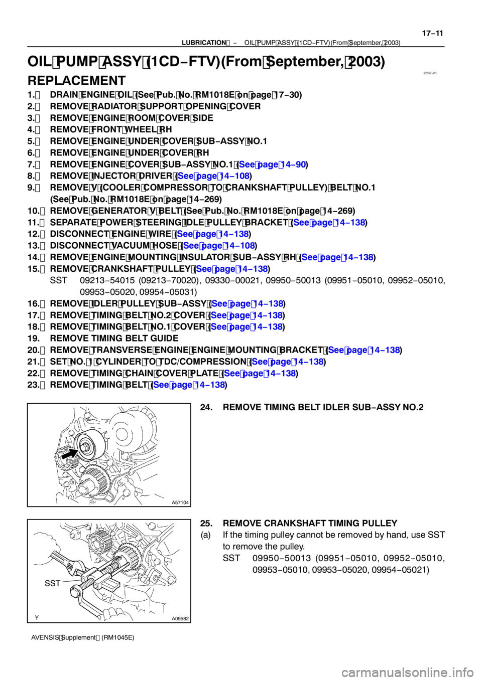
24. REMOVE TIMING BELT IDLER SUB −ASSY NO.2
25. REMOVE CRANKSHAFT TIMING PULLEY
(a) If the timing pulley cannot be removed by hand, use SST to remove the pulley.
SST 09950 −50013 (09951 −05010, 09952 −05010,
09953 −05010, 09953 −05020, 09954 −05021)
Page 4749 of 5135

B08016
O−ring
A85926
A56695
A79175
SST SST
17
−12
−
LUBRICATION OIL PUMP ASSY (1CD −FTV)(From September, 2003)
AVENSIS Supplement (RM1045E)
26. REMOVE FLOOR PANEL BRACE FRONT (See page 15 −6)
27. REMOVE EXHAUST PIPE ASSY FRONT (See page 15 −6)
28. REMOVE GENERATOR ASSY (See Pub. No. RM1018E on page 19 −29)
29. REMOVE TIMING BELT IDLER SUB −ASSY NO.1 (See page 16 −21)
30. REMOVE V −RIBBED BELT TENSIONER ASSY (See page 14 −108)
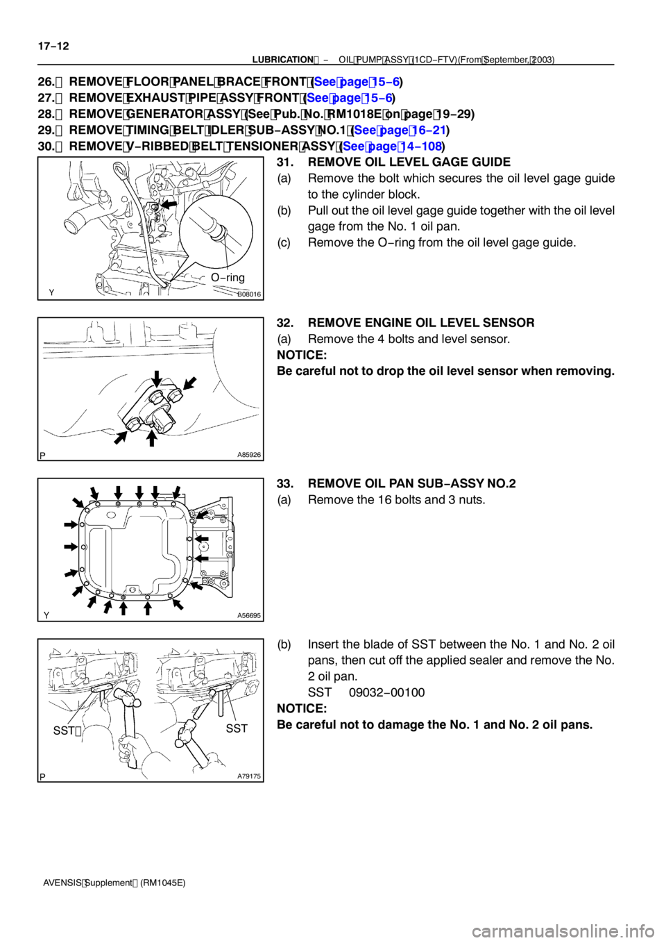
31. REMOVE OIL LEVEL GAGE GUIDE
(a) Remove the bolt which secures the oil level gage guide to the cylinder block.
(b) Pull out the oil level gage guide together with the oil level gage from the No. 1 oil pan.
(c) Remove the O −ring from the oil level gage guide.
32. REMOVE ENGINE OIL LEVEL SENSOR
(a) Remove the 4 bolts and level sensor.
NOTICE:
Be careful not to drop the oil level sensor when removing.
33. REMOVE OIL PAN SUB −ASSY NO.2
(a) Remove the 16 bolts and 3 nuts.
(b) Insert the blade of SST between the No. 1 and No. 2 oil pans, then cut off the applied sealer and remove the No.
2 oil pan.
SST 09032 −00100
NOTICE:
Be careful not to damage the No. 1 and No. 2 oil pans.
Page 4750 of 5135
A56696
B08009
A56697
A56698
−
LUBRICATION OIL PUMP ASSY (1CD −FTV)(From September, 2003)
17 −13
AVENSIS Supplement (RM1045E)
34. REMOVE OIL STRAINER SUB −ASSY
(a) Remove the 2 bolts and 2 nuts, then remove the oil strain- er and gasket.
35. REMOVE OIL PAN INSULATOR
(a) Remove the bolt and oil pan insulator.
36. REMOVE OIL PAN SUB −ASSY
(a) Remove the 19 bolts and 3 nuts.
(b) Using a screwdriver, remove the oil pan by prying be-
tween the cylinder block and No. 1 oil pan.
NOTICE:
Be careful not to damage the cylinder block and No. 1 oil
pan.
37. REMOVE CRANKSHAFT POSITION SENSOR (See page 14 −138)
Page 4751 of 5135

A56699
A56700
SST
B07987
New Gasket
Seal
Packing Seal Width
2to4mm
(0.08 to 0.16 in.)
B08024
17−14
− LUBRICATIONOIL PUMP ASSY (1CD−FTV)(From September, 2003)
AVENSIS Supplement (RM1045E)
38. REMOVE OIL PUMP ASSY
(a) Remove the 9 bolts.
(b) Remove the oil pump by prying between the oil pump and
main bearing cap using a screwdriver.
(c) Remove the gasket.
39. INSTALL CRANKSHAFT SEAL
(a) Using SST and a hammer, tap in a new oil seal until its sur-
face is flush with the oil pump edge.
SST 09316−60011 (09316−00011, 09316−00021)
40. INSTALL OIL PUMP ASSY
(a) Remove any old packing (FIPG). Be careful not to drop
any oil on the contact surfaces of the oil pump and cylin-
der block.
(1) Using a razor blade and gasket scraper, remove all
the old packing from the gasket surfaces and seal-
ing groove.
(2) Thoroughly clean all components to remove all the
loose material.
(3) Using a non−residue solvent, clean both the sealing
surfaces.
(b) Apply seal packing to the oil pump as shown in the illustra-
tion.
Seal packing: Part No. 08826−00080 or equivalent
NOTICE:
Avoid applying an excessive amount to the surface.
(1) Install a nozzle of which opening is cut to 2 to 4 mm
(0.08 to 0.16 in.).
(2) The parts must be set within 3 minutes and must be
assembled within 15 minutes after applying seal
packing. Otherwise the material must be removed
and reapplied.
(3) Immediately remove the nozzle from the tube, then
reinstall the cap.
(c) Install a new gasket to the oil pump.
(d) Pour 0.5 cm
3(0.03 cu in.) or more of engine oil into the
bushing of the cylinder block.
(e) Apply engine oil to the cylinder block side which contacts
the oil pump driven rotor.