Page 2478 of 5135
190NT±01
A81052
������������A82936
Type A
Type B
BlueWhite
Red Green DarkClear or
light yellow
B00543
19±18
± STARTING & CHARGINGCHARGING SYSTEM (1AZ±FSE)
AVENSIS REPAIR MANUAL (RM1018E)
ON±VEHICLE INSPECTION
1. CHECK BATTERY ELECTROLYTE LEVEL
(a) Check the electrolyte quantity of each cell.
(1) If the electrolyte is under the low level, replace the battery (or add distilled water if possible) and
check the charging system.
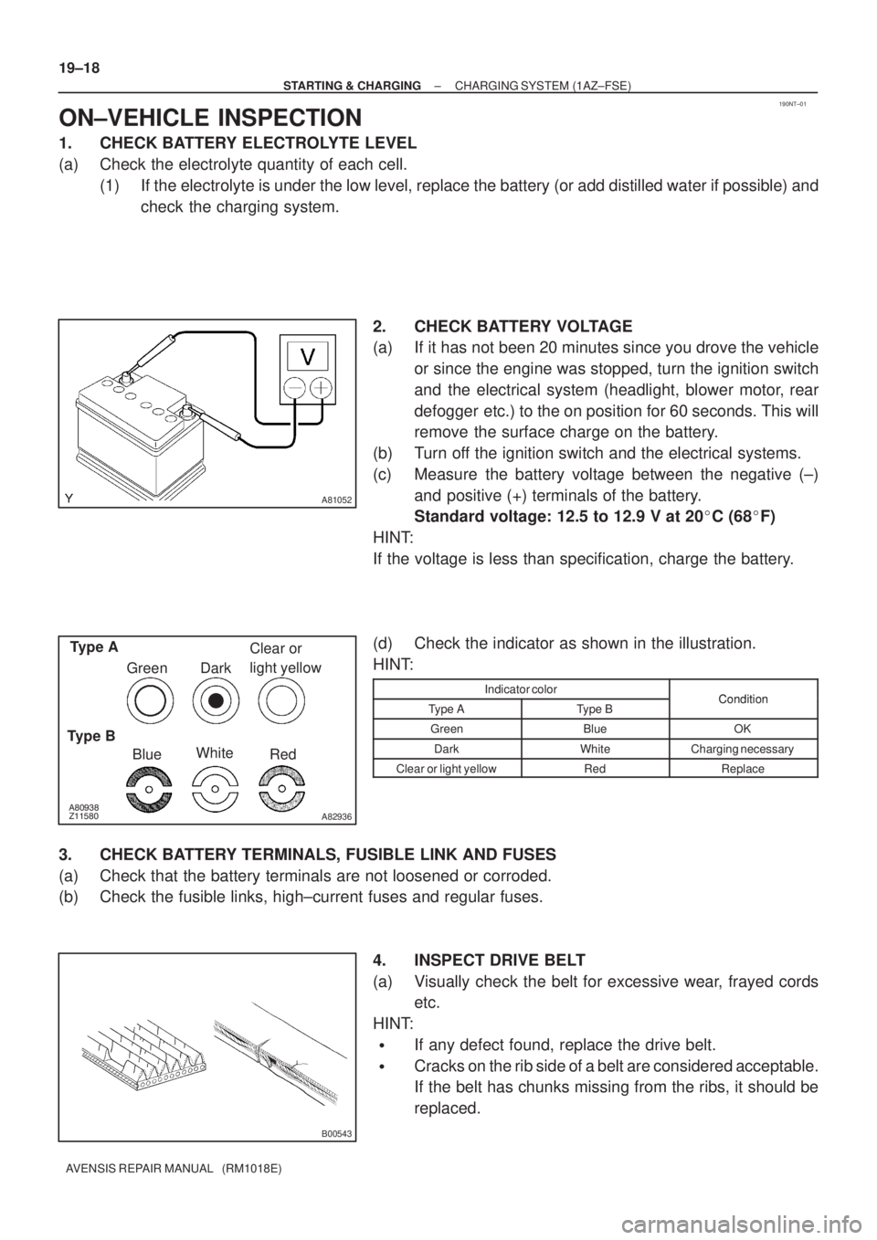
2. CHECK BATTERY VOLTAGE
(a) If it has not been 20 minutes since you drove the vehicle
or since the engine was stopped, turn the ignition switch
and the electrical system (headlight, blower motor, rear
defogger etc.) to the on position for 60 seconds. This will
remove the surface charge on the battery.
(b) Turn off the ignition switch and the electrical systems.
(c) Measure the battery voltage between the negative (±)
and positive (+) terminals of the battery.
Standard voltage: 12.5 to 12.9 V at 20�C (68�F)
HINT:
If the voltage is less than specification, charge the battery.
(d) Check the indicator as shown in the illustration.
HINT:
Indicator colorConditionType AType BCondition
GreenBlueOK
DarkWhiteCharging necessary
Clear or light yellowRedReplace
3. CHECK BATTERY TERMINALS, FUSIBLE LINK AND FUSES
(a) Check that the battery terminals are not loosened or corroded.
(b) Check the fusible links, high±current fuses and regular fuses.
4. INSPECT DRIVE BELT
(a) Visually check the belt for excessive wear, frayed cords
etc.
HINT:
�If any defect found, replace the drive belt.
�Cracks on the rib side of a belt are considered acceptable.
If the belt has chunks missing from the ribs, it should be
replaced.
Page 2481 of 5135
190NW±01
A81052
������������A82936
Type A
Type B
BlueWhite
Red Green DarkClear or
light yellow
B00543
± STARTING & CHARGINGCHARGING SYSTEM (1AZ±FE)
19±15
AVENSIS REPAIR MANUAL (RM1018E)
ON±VEHICLE INSPECTION
1. CHECK BATTERY ELECTROLYTE LEVEL
(a) Check the electrolyte quantity of each cell.
(1) If the electrolyte is under the low level, replace the battery (or add distilled water if possible) and
check the charging system.
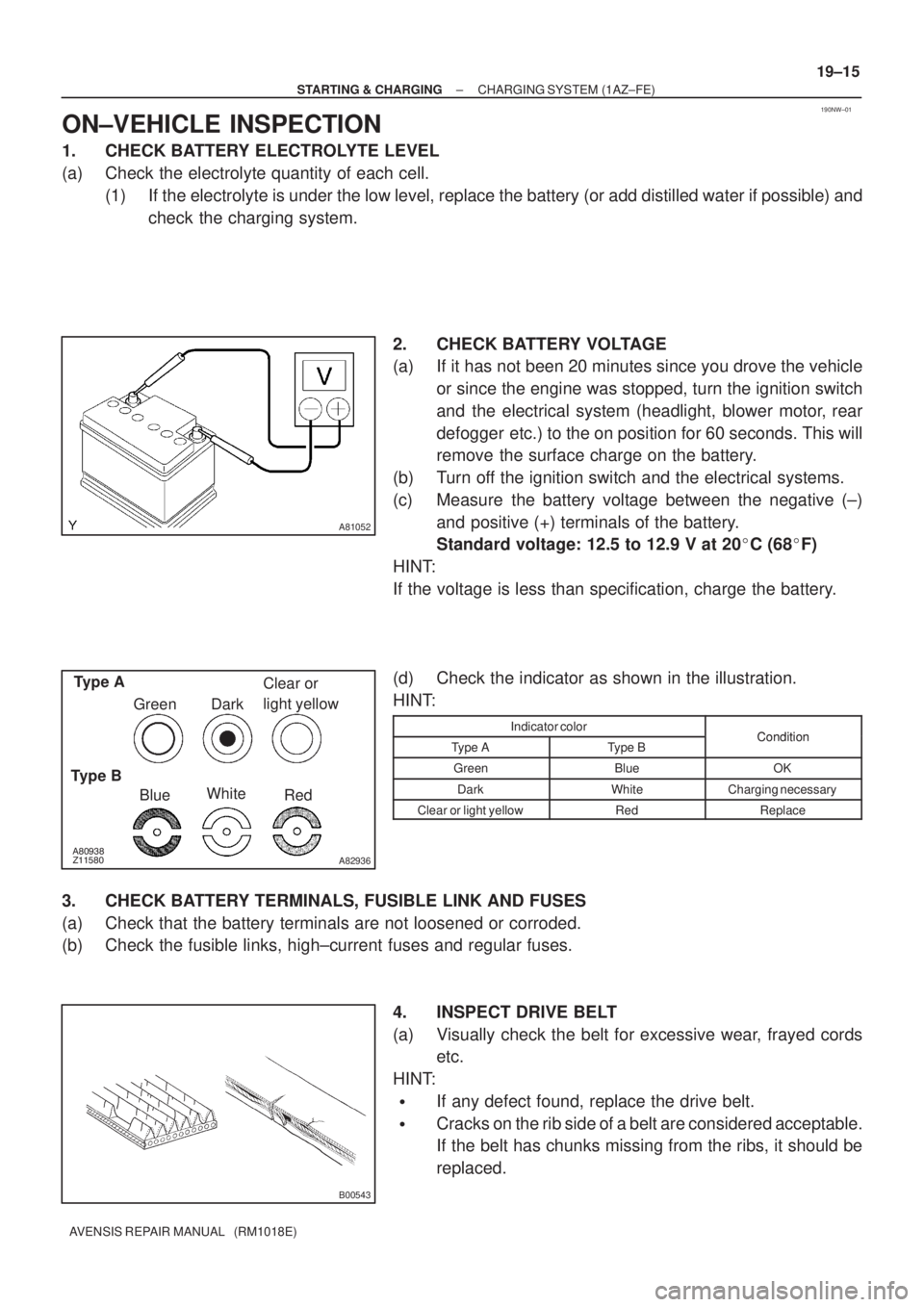
2. CHECK BATTERY VOLTAGE
(a) If it has not been 20 minutes since you drove the vehicle
or since the engine was stopped, turn the ignition switch
and the electrical system (headlight, blower motor, rear
defogger etc.) to the on position for 60 seconds. This will
remove the surface charge on the battery.
(b) Turn off the ignition switch and the electrical systems.
(c) Measure the battery voltage between the negative (±)
and positive (+) terminals of the battery.
Standard voltage: 12.5 to 12.9 V at 20�C (68�F)
HINT:
If the voltage is less than specification, charge the battery.
(d) Check the indicator as shown in the illustration.
HINT:
Indicator colorConditionType AType BCondition
GreenBlueOK
DarkWhiteCharging necessary
Clear or light yellowRedReplace
3. CHECK BATTERY TERMINALS, FUSIBLE LINK AND FUSES
(a) Check that the battery terminals are not loosened or corroded.
(b) Check the fusible links, high±current fuses and regular fuses.
4. INSPECT DRIVE BELT
(a) Visually check the belt for excessive wear, frayed cords
etc.
HINT:
�If any defect found, replace the drive belt.
�Cracks on the rib side of a belt are considered acceptable.
If the belt has chunks missing from the ribs, it should be
replaced.
Page 2577 of 5135
320GN±02
BR2238
GOOD NO GOOD
2nd3rd
1st
BR2237
G24221
Ventilation No Ventilation
± BRAKEBRAKE BOOSTER ASSY (RHD)
32±21
AVENSIS REPAIR MANUAL (RM1018E)
BRAKE BOOSTER ASSY (RHD)
ON±VEHICLE INSPECTION
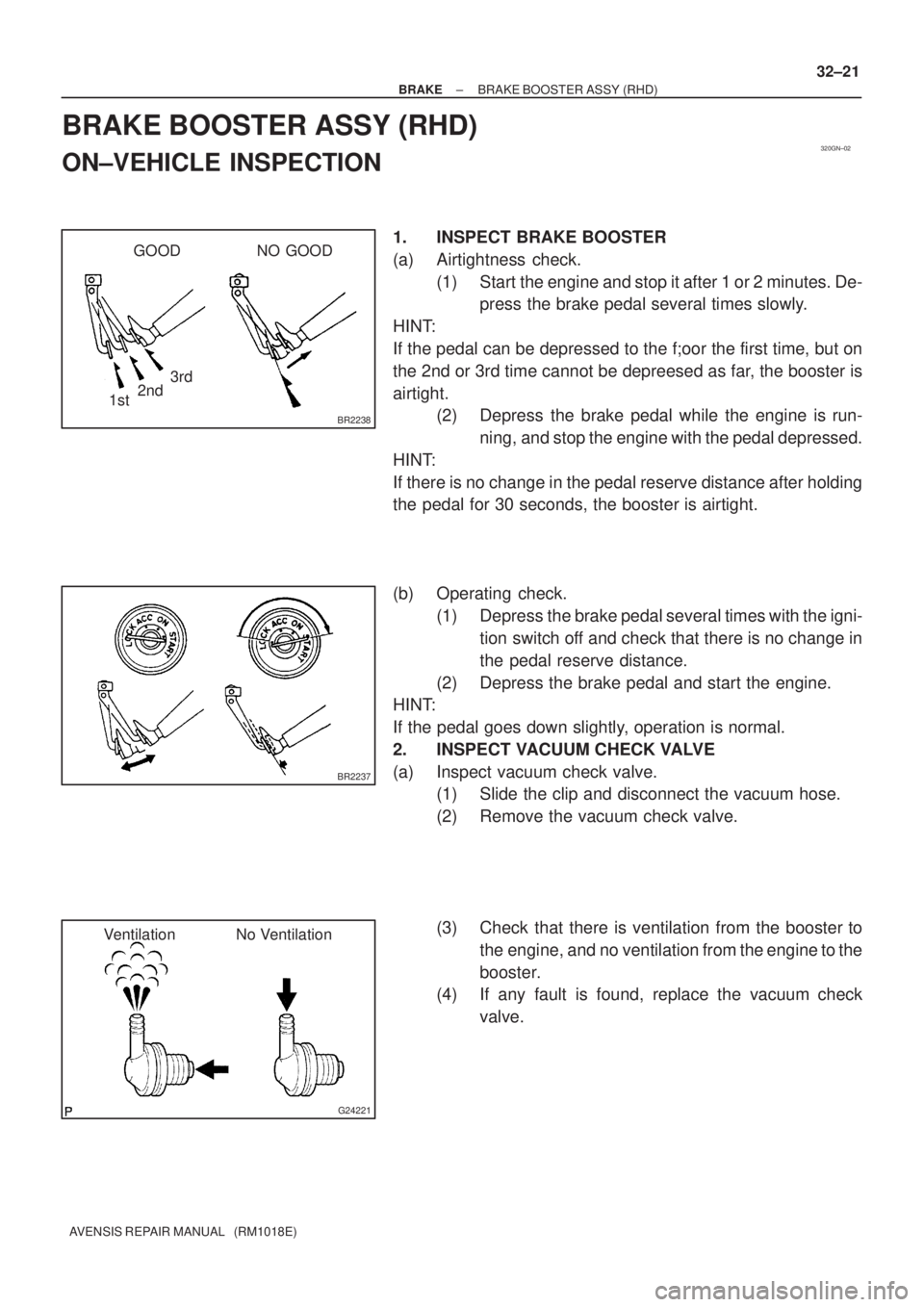
1. INSPECT BRAKE BOOSTER
(a) Airtightness check.
(1) Start the engine and stop it after 1 or 2 minutes. De-
press the brake pedal several times slowly.
HINT:
If the pedal can be depressed to the f;oor the first time, but on
the 2nd or 3rd time cannot be depreesed as far, the booster is
airtight.
(2) Depress the brake pedal while the engine is run-
ning, and stop the engine with the pedal depressed.
HINT:
If there is no change in the pedal reserve distance after holding
the pedal for 30 seconds, the booster is airtight.
(b) Operating check.
(1) Depress the brake pedal several times with the igni-
tion switch off and check that there is no change in
the pedal reserve distance.
(2) Depress the brake pedal and start the engine.
HINT:
If the pedal goes down slightly, operation is normal.
2. INSPECT VACUUM CHECK VALVE
(a) Inspect vacuum check valve.
(1) Slide the clip and disconnect the vacuum hose.
(2) Remove the vacuum check valve.
(3) Check that there is ventilation from the booster to
the engine, and no ventilation from the engine to the
booster.
(4) If any fault is found, replace the vacuum check
valve.
Page 2581 of 5135
3201G±07
BR2238
GOOD NO GOOD
2nd3rd
1st
BR2237
G24221
Ventilation No Ventilation
± BRAKEBRAKE BOOSTER ASSY (LHD)
32±17
AVENSIS REPAIR MANUAL (RM1018E)
BRAKE BOOSTER ASSY (LHD)
ON±VEHICLE INSPECTION
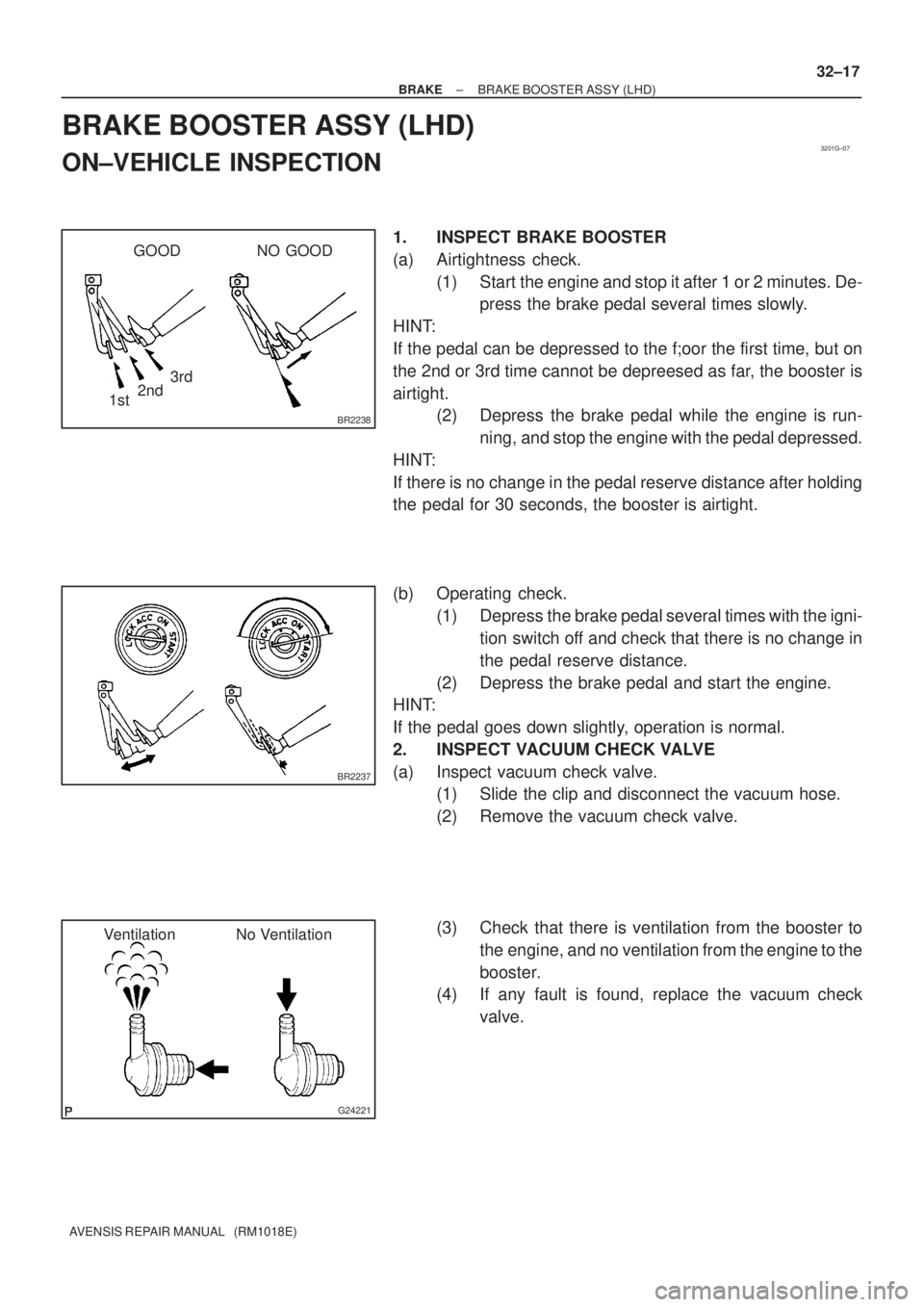
1. INSPECT BRAKE BOOSTER
(a) Airtightness check.
(1) Start the engine and stop it after 1 or 2 minutes. De-
press the brake pedal several times slowly.
HINT:
If the pedal can be depressed to the f;oor the first time, but on
the 2nd or 3rd time cannot be depreesed as far, the booster is
airtight.
(2) Depress the brake pedal while the engine is run-
ning, and stop the engine with the pedal depressed.
HINT:
If there is no change in the pedal reserve distance after holding
the pedal for 30 seconds, the booster is airtight.
(b) Operating check.
(1) Depress the brake pedal several times with the igni-
tion switch off and check that there is no change in
the pedal reserve distance.
(2) Depress the brake pedal and start the engine.
HINT:
If the pedal goes down slightly, operation is normal.
2. INSPECT VACUUM CHECK VALVE
(a) Inspect vacuum check valve.
(1) Slide the clip and disconnect the vacuum hose.
(2) Remove the vacuum check valve.
(3) Check that there is ventilation from the booster to
the engine, and no ventilation from the engine to the
booster.
(4) If any fault is found, replace the vacuum check
valve.
Page 2768 of 5135
CL0102Pedal Free Play
CL0512
25 mm (0.98 in.) or more
Release Point
Full Stroke
End Position
± CLUTCHCLUTCH PEDAL SUB±ASSY (MTM)
42±3
AVENSIS REPAIR MANUAL (RM1018E)
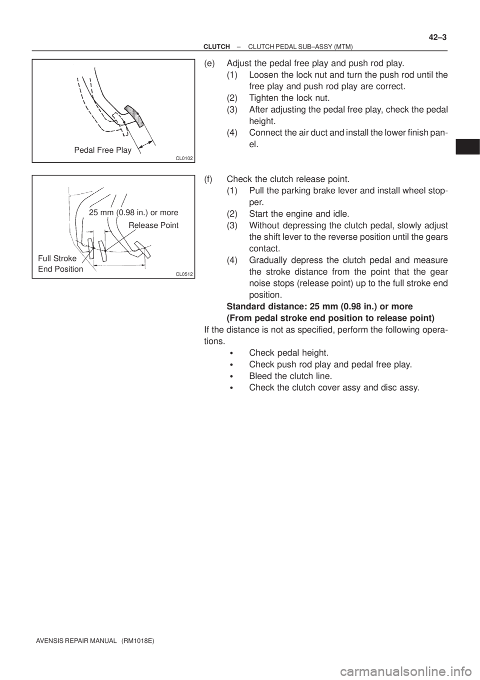
(e) Adjust the pedal free play and push rod play.
(1) Loosen the lock nut and turn the push rod until the
free play and push rod play are correct.
(2) Tighten the lock nut.
(3) After adjusting the pedal free play, check the pedal
height.
(4) Connect the air duct and install the lower finish pan-
el.
(f) Check the clutch release point.
(1) Pull the parking brake lever and install wheel stop-
per.
(2) Start the engine and idle.
(3) Without depressing the clutch pedal, slowly adjust
the shift lever to the reverse position until the gears
contact.
(4) Gradually depress the clutch pedal and measure
the stroke distance from the point that the gear
noise stops (release point) up to the full stroke end
position.
Standard distance: 25 mm (0.98 in.) or more
(From pedal stroke end position to release point)
If the distance is not as specified, perform the following opera-
tions.
�Check pedal height.
�Check push rod play and pedal free play.
�Bleed the clutch line.
�Check the clutch cover assy and disc assy.
Page 2880 of 5135
510DE±02
F40449
R11229
Normal
Abnormal
R00427
51±4
± POWER STEERINGPOWER STEERING SYSTEM
AVENSIS REPAIR MANUAL (RM1018E)
ON±VEHICLE INSPECTION
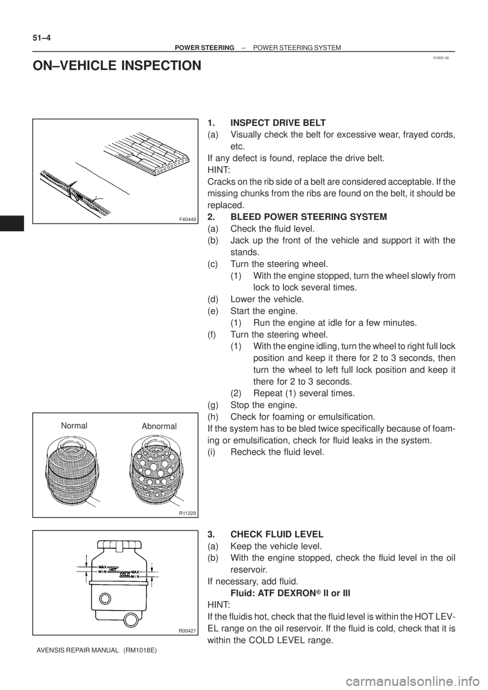
1. INSPECT DRIVE BELT
(a) Visually check the belt for excessive wear, frayed cords,
etc.
If any defect is found, replace the drive belt.
HINT:
Cracks on the rib side of a belt are considered acceptable. If the
missing chunks from the ribs are found on the belt, it should be
replaced.
2. BLEED POWER STEERING SYSTEM
(a) Check the fluid level.
(b) Jack up the front of the vehicle and support it with the
stands.
(c) Turn the steering wheel.
(1) With the engine stopped, turn the wheel slowly from
lock to lock several times.
(d) Lower the vehicle.
(e) Start the engine.
(1) Run the engine at idle for a few minutes.
(f) Turn the steering wheel.
(1) With the engine idling, turn the wheel to right full lock
position and keep it there for 2 to 3 seconds, then
turn the wheel to left full lock position and keep it
there for 2 to 3 seconds.
(2) Repeat (1) several times.
(g) Stop the engine.
(h) Check for foaming or emulsification.
If the system has to be bled twice specifically because of foam-
ing or emulsification, check for fluid leaks in the system.
(i) Recheck the fluid level.
3. CHECK FLUID LEVEL
(a) Keep the vehicle level.
(b) With the engine stopped, check the fluid level in the oil
reservoir.
If necessary, add fluid.
Fluid: ATF DEXRON� II or III
HINT:
If the fluidis hot, check that the fluid level is within the HOT LEV-
EL range on the oil reservoir. If the fluid is cold, check that it is
within the COLD LEVEL range.
Page 2881 of 5135
R11229
NormalAbnormal
R11786Engine Idling Engine Stopped5 mm (0.20 in.)
or less
±
POWER STEERING POWER STEERING SYSTEM
51±5
AVENSIS REPAIR MANUAL (RM1018E)
(c) Start the engine and run it at idle.
(d) Turn the steering wheel from lock to lock several times to
boost fluid temperature.
Fluid temperature: 80 �C (176 �F)
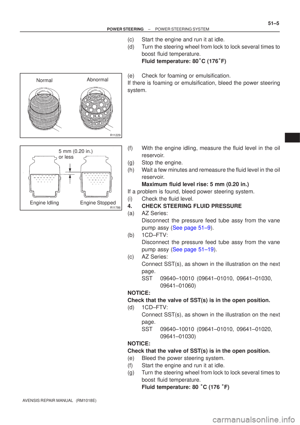
(e) Check for foaming or emulsification.
If there is foaming or emulsification, bleed the power steering
system.
(f) With the engine idling, measure the fluid level in the oil reservoir.
(g) Stop the engine.
(h) Wait a few minutes and remeasure the fluid level in the oil reservoir.
Maximum fluid level rise: 5 mm (0.20 in.)
If a problem is found, bleed power steering system.
(i) Check the fluid level.
4. CHECK STEERING FLUID PRESSURE
(a) AZ Series: Disconnect the pressure feed tube assy from the vane
pump assy (See page 51±9).
(b) 1CD±FTV: Disconnect the pressure feed tube assy from the vane
pump assy (See page 51±19).
(c) AZ Series: Connect SST(s), as shown in the illustration on the next
page.
SST 09640±10010 (09641±01010, 09641±01030, 09641±01060)
NOTICE:
Check that the valve of SST(s) is in the open position.
(d) 1CD±FTV: Connect SST(s), as shown in the illustration on the next
page.
SST 09640±10010 (09641±01010, 09641±01020, 09641±01030)
NOTICE:
Check that the valve of SST(s) is in the open position.
(e) Bleed the power steering system.
(f) Start the engine and run it at idle.
(g) Turn the steering wheel from lock to lock several times to
boost fluid temperature.
Fluid temperature: 80 �C (176 �F)
Page 2920 of 5135
550ZG±01
������������������I12508
Connector B
DTC Check Harness
Current DisplayControl PanelPast Record DTC Display
Memory Clear Button
DTC Calling Button
DTC Calling ButtonºHeatingº
Symbol In Normal
In Malfunction Connector A
± HEATER & AIR CONDITIONERCOMBUSTION TYPE POWER HEATER SYSTEM
55±15
AVENSIS REPAIR MANUAL (RM1018E)
COMBUSTION TYPE POWER HEATER SYSTEM
ON±VEHICLE INSPECTION
NOTICE:
�If the glow plug breaks, the ECU detects the breakage and stops the automatic operation, so
the burner heater does not activate. (For other failures, similarly activated.)
�The cause of failures (such as voltage malfunction, overheating malfunction, short±circuit or
breakage of functional components, etc.) and repair methods are shown by connecting the DTC
tester and reading the DTC.
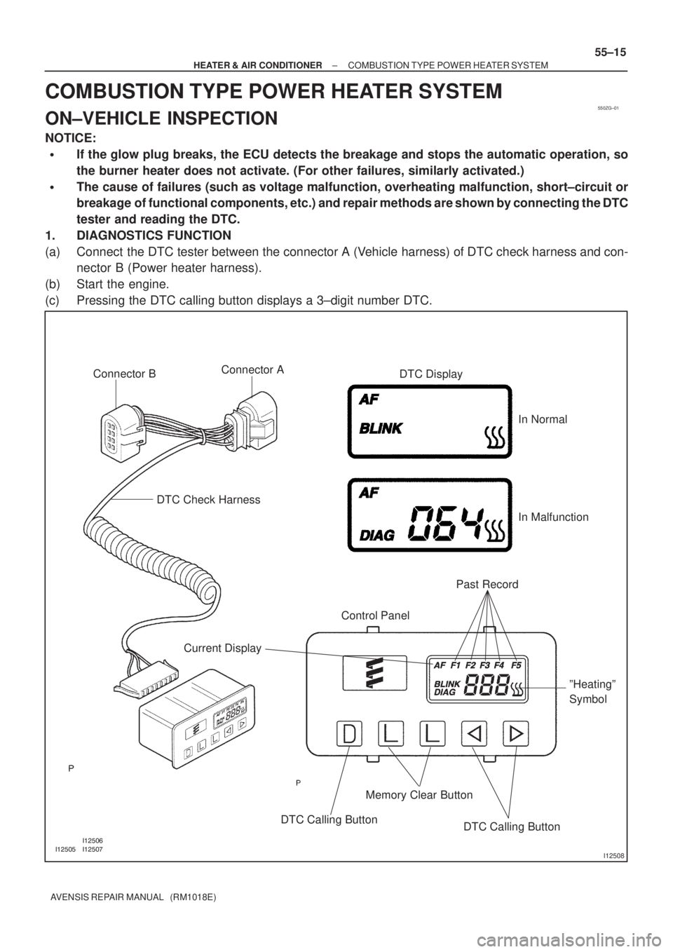
1. DIAGNOSTICS FUNCTION
(a) Connect the DTC tester between the connector A (Vehicle harness) of DTC check harness and con-
nector B (Power heater harness).
(b) Start the engine.
(c) Pressing the DTC calling button displays a 3±digit number DTC.