Page 2799 of 4555
![NISSAN X-TRAIL 2005 Service Repair Manual SERVICE DATA AND SPECIFICATIONS (SDS)
AT-535
[ALL]
D
E
F
G
H
I
J
K
L
MA
B
AT
*: Always check with the Parts Department for the latest parts information.
*: Always check with the Parts Department for](/manual-img/5/57403/w960_57403-2798.png "NISSAN X-TRAIL 2005 Service Repair Manual SERVICE DATA AND SPECIFICATIONS (SDS)
AT-535
[ALL]
D
E
F
G
H
I
J
K
L
MA
B
AT
*: Always check with the Parts Department for the latest parts information.
*: Always check with the Parts Department for")
SERVICE DATA AND SPECIFICATIONS (SDS)
AT-535
[ALL]
D
E
F
G
H
I
J
K
L
MA
B
AT
*: Always check with the Parts Department for the latest parts information.
*: Always check with the Parts Department for the latest parts information.
CLUTCH AND BRAKE RETURN SPRINGS
Unit: mm (in)
*: Always check with the Parts Department for the latest parts information.
BRAKE BAND
Final DriveECS00F1X
DIFFERENTIAL SIDE GEAR CLEARANCE
Drive plate thickness mm (in)Standard 1.8 (0.071)
Wear limit 1.6 (0.063)
Driven plate thickness mm (in) Standard 1.8 (0.071)
Clearance mm (in)Standard 1.7 - 2.1 (0.067 - 0.083)
Wear limit 3.3 (0.130)
Thickness of retaining platesThickness mm (in) Part number*
2.0 (0.079)
2.2 (0.087)
2.4 (0.094)
2.6 (0.102)
2.8 (0.110)
3.0 (0.118)
3.2 (0.126)
3.4 (0.134)31667-80X00
31667-80X01
31667-80X02
31667-80X03
31667-80X04
31667-80X05
31667-80X06
31667-80X07
Model code number85X64
Number of drive plates6
Number of driven plates6
Drive plate thickness mm (in)Standard 1.8 (0.071)
Wear limit 1.6 (0.063)
Driven plate thickness mm (in) Standard 1.8 (0.071)
Clearance mm (in)Standard 1.7 - 2.1 (0.067 - 0.083)
Wear limit 3.3 (0.130)
Thickness of retaining platesThickness mm (in) Part number*
2.0 (0.079)
2.2 (0.087)
2.4 (0.094)
2.6 (0.102)
2.8 (0.110)
3.0 (0.118)
3.2 (0.126)
3.4 (0.134)31667-80X00
31667-80X01
31667-80X02
31667-80X03
31667-80X04
31667-80X05
31667-80X06
31667-80X07
Parts Part number* Free length Outer diameter
Forward clutch (Overrun clutch)
(22 pcs)31505-80X02 21.4 (0.843) 10.3 (0.406)
High clutch (12 pcs) 31505-80X05 22.5 (0.886) 10.8 (0.425)
Low & reverse brake (24 pcs) 31505-80X07 24.1 (0.949) 6.6 (0.260)
Anchor end pin tightening torque N·m (kg-m, in-lb) 4.9 (0.50, 43)
Number of returning revolutions for anchor end pin 2.5
Lock nut tightening torque N·m (kg-m, ft-lb) 34 (3.5, 25)
Clearance between side gear and differential case with
washer mm (in)0.1 - 0.2 (0.004 - 0.008)
Page 2802 of 4555
![NISSAN X-TRAIL 2005 Service Repair Manual AT-538
[ALL]
SERVICE DATA AND SPECIFICATIONS (SDS)
*: Always check with the Parts Department for the latest parts information.
Band ServoECS00F21
RETURN SPRING
Unit: mm (in)
*: Always check with the](/manual-img/5/57403/w960_57403-2801.png "NISSAN X-TRAIL 2005 Service Repair Manual AT-538
[ALL]
SERVICE DATA AND SPECIFICATIONS (SDS)
*: Always check with the Parts Department for the latest parts information.
Band ServoECS00F21
RETURN SPRING
Unit: mm (in)
*: Always check with the")
AT-538
[ALL]
SERVICE DATA AND SPECIFICATIONS (SDS)
*: Always check with the Parts Department for the latest parts information.
Band ServoECS00F21
RETURN SPRING
Unit: mm (in)
*: Always check with the Parts Department for the latest parts information.
Output ShaftECS00F22
SEAL RING CLEARANCE
SEAL RING
*: Always check with the Parts Department for the latest parts information.
END PLAY
OUTPUT SHAFT ADJUSTING SHIMS
*: Always check with the Parts Department for the latest parts information.
Bearing RetainerECS00F23
SEAL RING CLEARANCE
Total End PlayECS00F24
Return spring Part number* Free length Outer diameter
2nd servo return spring 31605-31X20 32.5 (1.280) 25.9 (1.020)
O/D servo return spring 31605-80X07 31.0 (1.220) 62.6 (2.465)
Output shaft seal ring clearance mm
(in)Standard 0.10 - 0.25 (0.0039 - 0.0098)
Allowable limit 0.25 (0.0098)
Outer diameter mm (in) 1nner diameter mm (in) Width mm (in) Part number*
33.71 (1.327) 30.25 (1.191) 1.95 (0.077) 31525 80X09
Output shaft end play mm (in) 0 - 0.15 (0 - 0.0059)
Thickness mm (in) Part number*
0.80 (0.0315)
0.84 (0.0331)
0.88 (0.0346)
0.92 (0.0362)
0.96 (0.0378)
1.00 (0.0394)
1.04 (0.0409)
1.08 (0.0425)
1.12 (0.0441)
1.16 (0.0457)
1.20 (0.0472)31438-80X60
31438-80X61
31438-80X62
31438-80X63
31438-80X64
31438-80X65
31438-80X66
31438-80X67
31438-80X68
31438-80X69
31438-80X70
Bearing retainer seal ring
clearance mm (in)Standard 0.10 - 0.30 (0.0039 - 0.0118)
Allowable limit 0.30 (0.0118)
Total end play mm (in) 0.25 - 0.55 (0.0098 - 0.0217)
Page 2862 of 4555
TF-58
TRANSFER ASSEMBLY
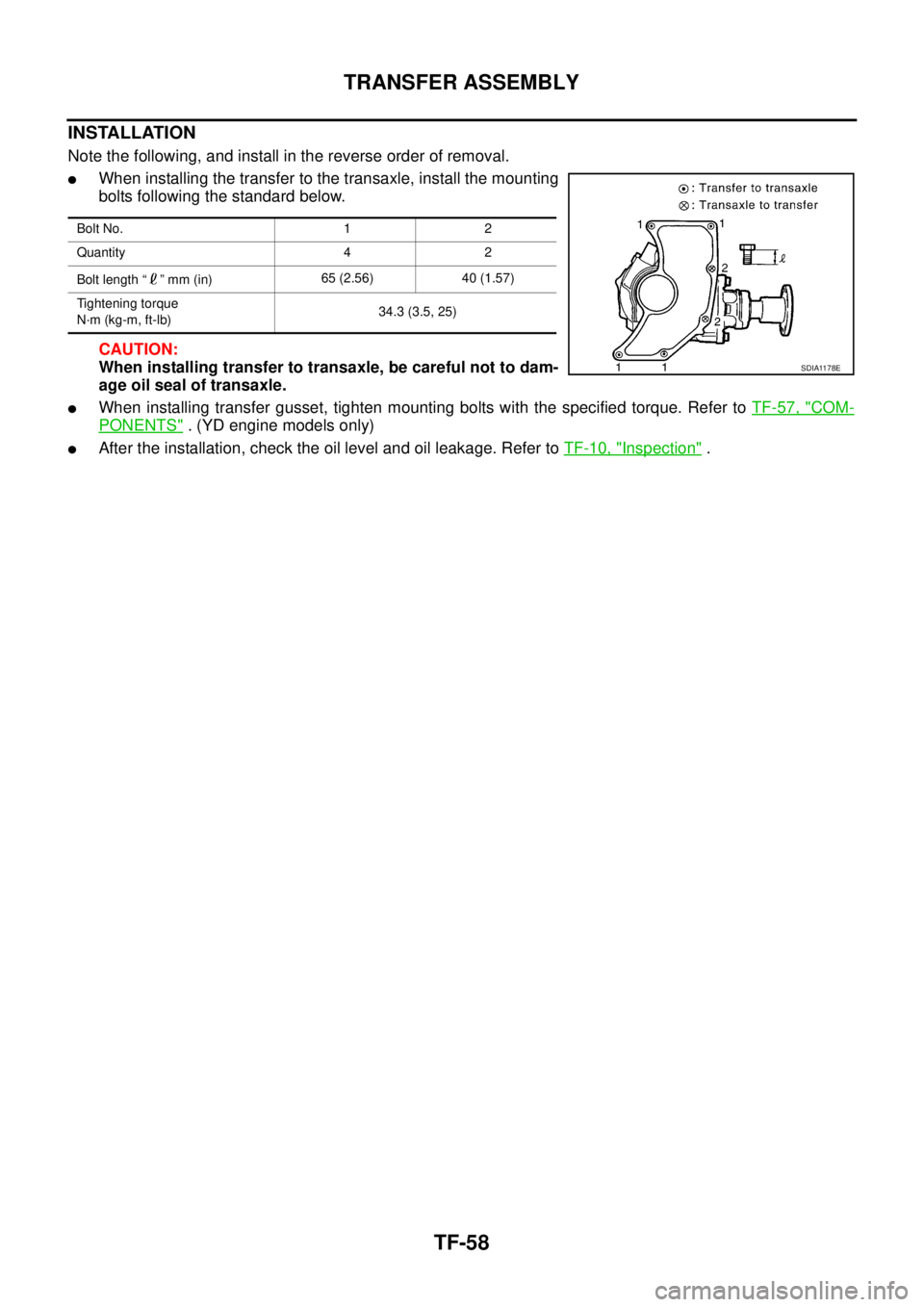
INSTALLATION
Note the following, and install in the reverse order of removal.
�When installing the transfer to the transaxle, install the mounting
bolts following the standard below.
CAUTION:
When installing transfer to transaxle, be careful not to dam-
age oil seal of transaxle.
�When installing transfer gusset, tighten mounting bolts with the specified torque. Refer to TF-57, "COM-
PONENTS" . (YD engine models only)
�After the installation, check the oil level and oil leakage. Refer to TF-10, "Inspection" .
Bolt No. 1 2
Quantity 4 2
Bolt length “ ” mm (in)65 (2.56) 40 (1.57)
Tightening torque
N·m (kg-m, ft-lb)34.3 (3.5, 25)
SDIA1178E
Page 2877 of 4555

TRANSFER ASSEMBLY
TF-73
C
E
F
G
H
I
J
K
L
MA
B
TF
4. Using the suitable drift, drive the adapter case oil seal until it
becomes flush with the case end.
CAUTION:
�When checking the total preload torque, measure it with-
out the oil seal, then install the oil seal.
�Do not reuse the oil seal.
�Apply multi-purpose grease onto oil seal lips, and gear
oil onto the circumference of the oil seal.
5. Apply recommended sealant on drain plug and install it to the
adapter case. Refer to TF-59, "
COMPONENTS" .
6. Apply multi-purpose grease lightly and evenly onto an O-ring,
and install it to the adapter case.
CAUTION:
Do not reuse the O-ring.
7. Install the adapter case to the transfer case, and apply anti-cor-
rosive oil onto threads and seats on the mounting bolts. Tighten
to the specified torque.
8. Check backlash, preload torque, tooth contact, and companion
flange runout. Refer to TF-60, "
ASSEMBLY INSPECTION" .
CAUTION:
Measure the total preload torque without the oil seal.
Bolt symbol
Bolt length “ ” mm (in)Tightening torque
N·m (kg-m, ft-lb)
A 35 (1.38)
15.2 (1.6, 11)
B 30 (1.18)
PDIA0922E
SDIA2318E
Page 2889 of 4555
SERVICE DATA AND SPECIFICATIONS (SDS)
PR-7
C
E
F
G
H
I
J
K
L
MA
B
PR
SERVICE DATA AND SPECIFICATIONS (SDS)PFP:00030
General SpecificationsEDS0027D
Journal Axial PlayEDS0027E
Propeller Shaft RunoutEDS0027F
Applied model QR20DE, QR25DE, YD22DDTi
Propeller shaft model 3F63A-DOJ75
Number of joints3
Coupling method with transfer Flange
Type of journal bearings Shell type (Non-disassembly type)
Shaft length 1st (spider to cardan joint center) 1,041 mm (40.98 in)
2nd (cardan joint center to spider) 934mm (36.77 in)
Shaft outer diameter1st 63.5 mm (2.500 in)
2nd 70.0 mm (2.76 in)
Model3F63A-DOJ75
Journal axial play0 mm (0 in)
Model3F63A-DOJ75
Propeller shaft runout limit 0.6 mm (0.024 in) or less
Page 2939 of 4555

FRONT DRIVE SHAFT
FAX-15
C
E
F
G
H
I
J
K
L
MA
B
FA X
ASSEMBLY
Transaxle Side
1. Wind serrated part of drive shaft with tape. Install boot band and
boot to shaft. Be careful not to damage boot.
CAUTION:
Discard the old boot band and boot: replace with new ones.
2. Remove protective tape wound around serrated part of shaft.
3. Line up alignment marks which were made when spider assem-
bly was removed. Install spider assembly, with serration chamfer
facing drive shaft.
4. Secure spider assembly with snap ring.
CAUTION:
Discard the old snap ring: replace with new ones.
5. Apply Nissan genuine grease or equivalent to spider assembly
and sliding surface.
6. Install sliding joint housing to spider assembly. Add remaining
grease up to the amount listed below.
7. Install boot securely into grooves (indicated by * marks) shown
in the figure.
CAUTION:
If there is grease on boot mounting surfaces (indicated by *
marks) of joint, boot may come off. Remove all grease from
surfaces.
8. Check that boot installation length “L” is the length indicated
below. Insert flat bladed screwdriver or similar tool into smaller
side of boot. Remove air from boot to prevent boot deformation.
CAUTION:
�Boot may break if boot installation length is less than
standard value.
�Be careful that screwdriver tip does not contact inside
surface of boot.
SDIA0597E
Grease amount : 132 - 142 g (4.69 - 5.04 oz)
SDIA0598E
SDIA0599E
Boot installation length:
84 - 86 mm (3.31 - 3.39 in)
SDIA0600E
Page 2941 of 4555
 shown
in the figure.
CAUTION:
If there is grease on boot mounting surfaces (indicat")
FRONT DRIVE SHAFT
FAX-17
C
E
F
G
H
I
J
K
L
MA
B
FA X
7. Install boot securely into grooves (indicated by * marks) shown
in the figure.
CAUTION:
If there is grease on boot mounting surfaces (indicated by*
marks) of shaft and housing, boot may come off. Remove
all grease from surface.
8. Make sure boot installation length “L” is the length indicated
below. Insert a flat-bladed screwdriver or similar tool into smaller
side of boot. Bleed air from boot to prevent boot deformation.
CAUTION:
�Boot may brake if boot installation length is than standard value.
�Be careful that screwdriver tip does not contact inside surface of boot.
9. Install new larger and smaller boot bands securely with a suit-
able tool.
CAUTION:
�Secure boot band so that dimension “M” shown at right
satisfies the following:
10. After installing housing and shaft, rotate boot to check whether
or not the actual position is correct, secure boot with new boot
bands again.
Dynamic Damper
�When dynamic damper has been removed, secure with bands
as shown in the figure so that measurements from fixed-joint
side are as listed below.
CAUTION:
Discard the old dynamic damper: replace with a new one.Boot installation length “L” : 100 – 103 mm (3.94 –
4.06 in)
SDIA1505E
RAC1133D
Dimension “M” : 2.0 – 3.0 mm (0.079 – 0.018 in)
DSF0047D
FAC0156D
Page 2943 of 4555
SERVICE DATA AND SPECIFICATIONS (SDS)
FAX-19
C
E
F
G
H
I
J
K
L
MA
B
FA X
SERVICE DATA AND SPECIFICATIONS (SDS)PFP:00030
Wheel BearingEDS000IG
Drive ShaftEDS000IH
ZF100SS86, ZF100SS86F, ZF100SS86F+B
Dynamic DamperEDS000II
Axial end play 0.05 mm (0.0020 in)
Rotating torque 1.645 N·m (0.17 kg-m, 15 in-lb) or less
Spring balance reading 10.6 N (1.1 kg, 2.4 lb) or less
Installation location of spring scale
SDIA0148E
Joint type Wheel side Transaxle side
Grease amount 115 - 125 g (4.01 - 4.41 oz) 132 - 142 g (4.69 - 5.04 oz)
Boot length 100 - 103 mm (3.94 - 4.06 in) 84 - 86 mm (3.31 - 3.39 in)
Drive shaft model Applied model Specification Dimension A Dimension B
ZF100SS86 ALL Left 205 - 215 mm (8.07 - 8.46 in) 70 mm (2.76 in)
ZF100SS86F+ BRHD: QR25DE A/T models
QR25DE: M/T models
Right 267 - 273 mm (10.51 - 10.75 in)70 mm (2.76 in)
QR20DE/YD22DDTi M/T models 50 mm (1.97 in)
FAC0156D

PR-7
C
E
F
G
H
I
J
K
L
MA
B
PR
SERVICE DATA AND SPECIFICATIONS (SDS)PFP:00030
General SpecificationsEDS0027D
Journal Axial PlayEDS0027E
Propeller Shaft RunoutED")

FAX-19
C
E
F
G
H
I
J
K
L
MA
B
FA X
SERVICE DATA AND SPECIFICATIONS (SDS)PFP:00030
Wheel BearingEDS000IG
Drive ShaftEDS000IH
ZF100SS86, ZF100SS86F, ZF100SS86F+B")