Page 2670 of 4555
AT-406
[ALL]
ON-VEHICLE SERVICE
7. Remove control valve assembly by removing fixing bolts A, B
and C .
CAUTION:
Be careful not to drop manual valve and servo release accu-
mulator return springs.
Bolt length, number and location:
8. Remove manual valve from control valve assembly.
CAUTION:
Be careful not to drop manual valve.
9. Disassemble and inspect control valve assembly if necessary. Refer to AT- 4 4 8 , "
Control Valve Assembly"
AT- 4 5 7 , "Control Valve Upper Body" and AT- 4 6 1 , "Control Valve Lower Body" .
10. Remove servo release accumulator and N-D accumulator by
applying compressed air if necessary.
�Hold each piston with a paper towel.
AAT260A
Bolt symbol A B C
Bolt length “ ” mm (in)40.0 mm
(1.575 in)33.0 mm
(1.299 in)43.5 mm
(1.713 in)
Number of bolts 5 6 2
SCIA3150E
SAT935J
Page 2679 of 4555
![NISSAN X-TRAIL 2005 Service Repair Manual REMOVAL AND INSTALLATION
AT-415
[ALL]
D
E
F
G
H
I
J
K
L
MA
B
AT
21. Remove fluid cooler tube.
INSPECTION
Installation and inspection of torque converter
� After inserting a torque converter to a tra](/manual-img/5/57403/w960_57403-2678.png "NISSAN X-TRAIL 2005 Service Repair Manual REMOVAL AND INSTALLATION
AT-415
[ALL]
D
E
F
G
H
I
J
K
L
MA
B
AT
21. Remove fluid cooler tube.
INSPECTION
Installation and inspection of torque converter
� After inserting a torque converter to a tra")
REMOVAL AND INSTALLATION
AT-415
[ALL]
D
E
F
G
H
I
J
K
L
MA
B
AT
21. Remove fluid cooler tube.
INSPECTION
Installation and inspection of torque converter
� After inserting a torque converter to a transaxle, be sure to
check distance “A” to ensure it is within the reference value limit.
InstallationECS004ND
Install the removed parts in the reverse order of the removal, while paying attention to the following work.
�When installing transaxle to the engine, attach the fixing bolts in
accordance with the following standard.
�Align the positions of tightening bolts for drive plate with those of
the torque converter, and temporarily tighten the bolts. Then,
tighten the bolts to the specified torque. Refer to AT- 4 1 6 , "
Com-
ponents" .
CAUTION:
�When turning crankshaft, turn it clockwise as viewed from
the front of the engine.
�When tightening the tightening bolts for the torque con-
verter after fixing the crankshaft pulley bolts, be sure to
confirm the tightening torque of the crankshaft pulley
mounting bolts.
� After converter is installed to drive plate, rotate crankshaft
several turns and check to be sure that transaxle rotates freely without binding.
�After completing installation, check for fluid leakage, fluid level, and the positions of A/T. Refer to AT- 1 6 ,
"Checking A/T Fluid" , AT- 4 0 9 , "CONTROL CABLE ADJUSTMENT" .
SCIA2596E
Distance “A”
QR20DE models: 19.0 mm (0.75 in) or more
QR25DE models: 14.0 mm (0.55 in) or more
SAT573D
Bolt No.Tightening torque
N·m (kg-m, ft-lb)Bolt length “ L ”
mm (in)
1
75 (7.7, 55)49 (1.93)
2 45 (1.77)
3
43 (4.4, 32)40 (1.57)
4 30 (1.18)
5
36 (3.7, 27)40 (1.57)
6 45 (1.97)
SCIA0795E
SCIA3138E
Page 2690 of 4555
AT-426
[ALL]
DISASSEMBLY
c. Remove control valve assembly mounting bolts A, B and C .
Bolt length, number and location:
d. Remove control valve assembly from transaxle case.
13. Remove manual valve from control valve assembly.
CAUTION:
Be careful not to drop manual valve and servo release accu-
mulator return springs.
14. Remove O-ring from terminal body.
15. Remove return spring from servo release accumulator piston.
Bolt symbol A B C
Bolt length “ ” mm (in)40.0 mm
(1.575 in)33.0 mm
(1.299 in)43.5 mm
(1.713 in)
Number of bolts 5 6 2
AAT260A
SAT005F
SCIA4741E
Page 2691 of 4555
![NISSAN X-TRAIL 2005 Service Repair Manual DISASSEMBLY
AT-427
[ALL]
D
E
F
G
H
I
J
K
L
MA
B
AT
16. Remove servo release accumulator piston with compressed air.
CAUTION:
�Strong flow of air will push the accumulator piston out
along with a spl](/manual-img/5/57403/w960_57403-2690.png "NISSAN X-TRAIL 2005 Service Repair Manual DISASSEMBLY
AT-427
[ALL]
D
E
F
G
H
I
J
K
L
MA
B
AT
16. Remove servo release accumulator piston with compressed air.
CAUTION:
�Strong flow of air will push the accumulator piston out
along with a spl")
DISASSEMBLY
AT-427
[ALL]
D
E
F
G
H
I
J
K
L
MA
B
AT
16. Remove servo release accumulator piston with compressed air.
CAUTION:
�Strong flow of air will push the accumulator piston out
along with a splash of oil.Cover the area with paper tow-
els and blow air little by little to avoid this.
�Wrap the removed accumulator piston in a paper towel.
17. Remove O-rings from servo release accumulator piston.
18. Remove N-D accumulator piston and return spring with com-
pressed air.
CAUTION:
�Strong flow of air will push the accumulator piston out
along with a splash of oil.Cover the area with paper tow-
els and blow air little by little to avoid this.
�Wrap the removed accumulator piston in a paper towel.
19. Remove O-rings from N-D accumulator piston.
20. Check accumulator pistons and contact surface of transaxle
case for damage.
21. Check accumulator return springs for damage and free length.
22. Remove lip seals.
23. Remove low & reverse brake tube and oil sleeve.
SAT019DA
SAT020D
SAT023DA
SCIA4867E
SCIA3478E
Page 2713 of 4555
REPAIR FOR COMPONENT PARTS
AT-449
[ALL]
D
E
F
G
H
I
J
K
L
MA
B
AT
DISASSEMBLY
Disassemble upper, inter and lower bodies.
Bolt length, number and location:
f: Reamer bolt and nut.
1. Remove bolts a, d , reamer bolt f and nut and remove oil
strainer from control valve assembly.
2. Remove bolts a, c, g , solenoid valve assembly and line pres-
sure solenoid valve from control valve assembly.
Bolt symbolabcde f g
Bolt length “ ” mm (in)
13.5
(0.531)58.0
(2.283)40.0
(1.575)66.0
(2.598)33.0
(1.299)78.0
(3.071)18.0
(0.709)
Number of bolts 6 3 6 11 2 2 1
SCIA4974E
SCIA4439E
SCIA4438E
Page 2717 of 4555
REPAIR FOR COMPONENT PARTS
AT-453
[ALL]
D
E
F
G
H
I
J
K
L
MA
B
AT
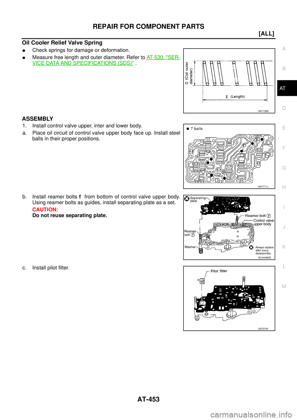
Oil Cooler Relief Valve Spring
�Check springs for damage or deformation.
�Measure free length and outer diameter. Refer to AT- 5 3 0 , "SER-
VICE DATA AND SPECIFICATIONS (SDS)" .
ASSEMBLY
1. Install control valve upper, inter and lower body.
a. Place oil circuit of control valve upper body face up. Install steel
balls in their proper positions.
b. Install reamer bolts f from bottom of control valve upper body.
Using reamer bolts as guides, install separating plate as a set.
CAUTION:
Do not reuse separating plate.
c. Install pilot filter.
SAT138D
SAT771J
SCIA4980E
SAT074F
Page 2719 of 4555
REPAIR FOR COMPONENT PARTS
AT-455
[ALL]
D
E
F
G
H
I
J
K
L
MA
B
AT
2. Install O-rings to solenoid valves and terminal body.
CAUTION:
�Do not reuse O-rings.
�Apply ATF to O-rings.
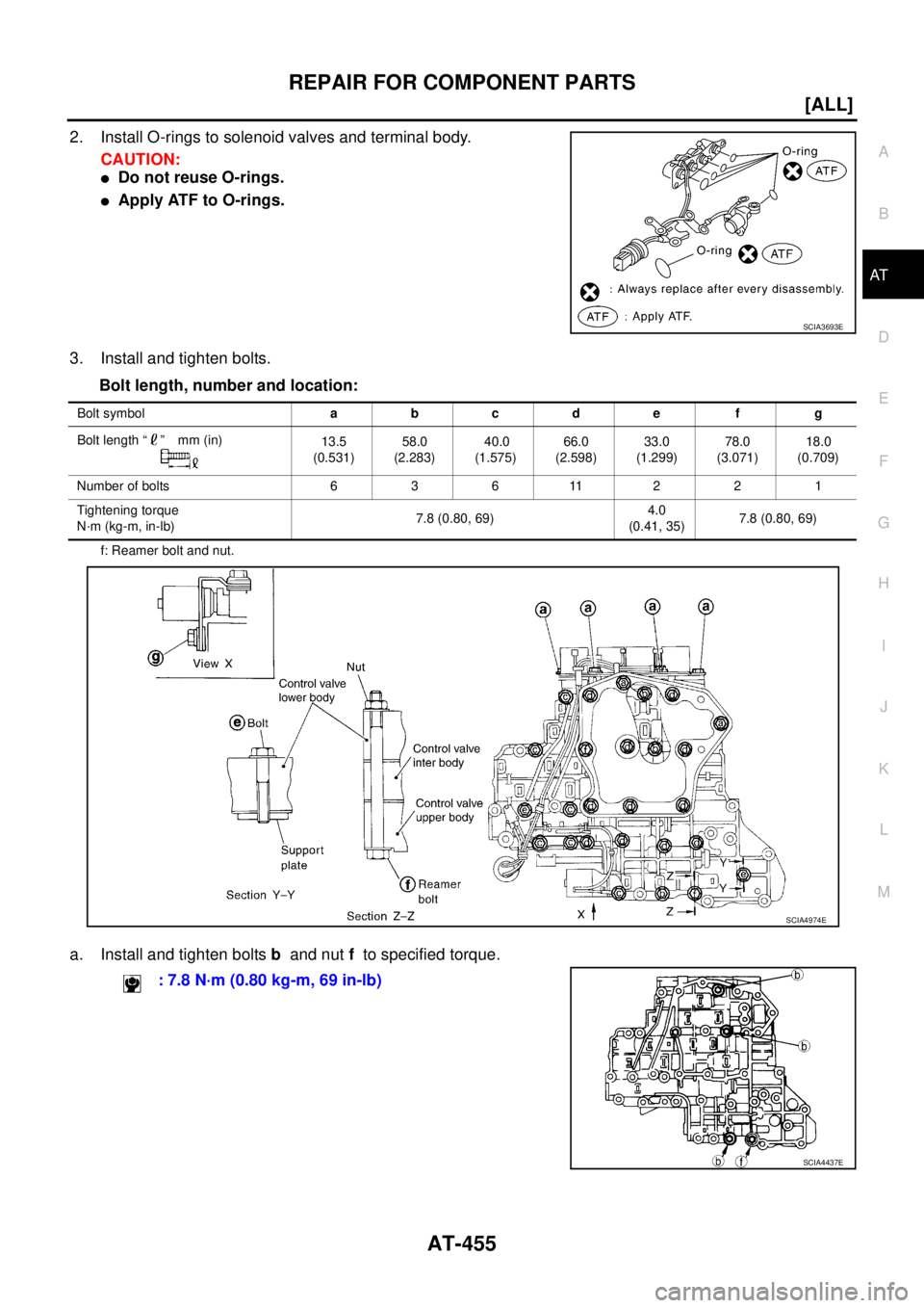
3. Install and tighten bolts.
Bolt length, number and location:
f: Reamer bolt and nut.
a. Install and tighten bolts b and nut f to specified torque.
SCIA3693E
Bolt symbolabcde f g
Bolt length “ ” mm (in)
13.5
(0.531)58.0
(2.283) 40.0
(1.575)66.0
(2.598)33.0
(1.299)78.0
(3.071)18.0
(0.709)
Number of bolts 6 3 6 11 2 2 1
Tightening torque
N·m (kg-m, in-lb)7.8 (0.80, 69)4.0
(0.41, 35)7.8 (0.80, 69)
SCIA4974E
: 7.8 N·m (0.80 kg-m, 69 in-lb)
SCIA4437E
Page 2723 of 4555
![NISSAN X-TRAIL 2005 Service Repair Manual REPAIR FOR COMPONENT PARTS
AT-459
[ALL]
D
E
F
G
H
I
J
K
L
MA
B
AT
c. Place mating surface of valve body face down, and remove
internal parts.
CAUTION:
�If a valve is hard to remove, place valve body](/manual-img/5/57403/w960_57403-2722.png "NISSAN X-TRAIL 2005 Service Repair Manual REPAIR FOR COMPONENT PARTS
AT-459
[ALL]
D
E
F
G
H
I
J
K
L
MA
B
AT
c. Place mating surface of valve body face down, and remove
internal parts.
CAUTION:
�If a valve is hard to remove, place valve body")
REPAIR FOR COMPONENT PARTS
AT-459
[ALL]
D
E
F
G
H
I
J
K
L
MA
B
AT
c. Place mating surface of valve body face down, and remove
internal parts.
CAUTION:
�If a valve is hard to remove, place valve body face down
and lightly tap it with a soft hammer.
�Be careful not to drop or damage valves and sleeves.
INSPECTION
Valve Spring
�Measure free length and outer diameter of each valve spring.
Also check for damage or deformation. Refer to AT- 5 3 0 , "
SER-
VICE DATA AND SPECIFICATIONS (SDS)" .
�Replace valve springs if deformed or fatigued.
Control Valves
�Check sliding surfaces of valves, sleeves and plugs.
ASSEMBLY
CAUTION:
�Apply ATF to all components before installation.
�Lay control valve body down when installing valves. Do not
stand control valve body upright.
�Lubricate control valve body and all valves with ATF. Install con-
trol valves by sliding them carefully into their bores.
CAUTION:
�Install each control valve one by one.
�Install control valves after checking, because some of
them are similar.
�Be careful not to scratch or damage valve body.
SAT137D
SAT138D
SAT139D
SAT140DA
![NISSAN X-TRAIL 2005 Service Repair Manual AT-406
[ALL]
ON-VEHICLE SERVICE
7. Remove control valve assembly by removing fixing bolts A, B
and C .
CAUTION:
Be careful not to drop manual valve and servo release accu-
mulator return springs.
Bo](/manual-img/5/57403/w960_57403-2669.png "NISSAN X-TRAIL 2005 Service Repair Manual AT-406
[ALL]
ON-VEHICLE SERVICE
7. Remove control valve assembly by removing fixing bolts A, B
and C .
CAUTION:
Be careful not to drop manual valve and servo release accu-
mulator return springs.
Bo")
![NISSAN X-TRAIL 2005 Service Repair Manual AT-426
[ALL]
DISASSEMBLY
c. Remove control valve assembly mounting bolts A, B and C .
Bolt length, number and location:
d. Remove control valve assembly from transaxle case.
13. Remove manual valve](/manual-img/5/57403/w960_57403-2689.png "NISSAN X-TRAIL 2005 Service Repair Manual AT-426
[ALL]
DISASSEMBLY
c. Remove control valve assembly mounting bolts A, B and C .
Bolt length, number and location:
d. Remove control valve assembly from transaxle case.
13. Remove manual valve")
![NISSAN X-TRAIL 2005 Service Repair Manual REPAIR FOR COMPONENT PARTS
AT-449
[ALL]
D
E
F
G
H
I
J
K
L
MA
B
AT
DISASSEMBLY
Disassemble upper, inter and lower bodies.
Bolt length, number and location:
f: Reamer bolt and nut.
1. Remove bolts a,](/manual-img/5/57403/w960_57403-2712.png "NISSAN X-TRAIL 2005 Service Repair Manual REPAIR FOR COMPONENT PARTS
AT-449
[ALL]
D
E
F
G
H
I
J
K
L
MA
B
AT
DISASSEMBLY
Disassemble upper, inter and lower bodies.
Bolt length, number and location:
f: Reamer bolt and nut.
1. Remove bolts a,")