Page 2724 of 4555
![NISSAN X-TRAIL 2005 Service Repair Manual AT-460
[ALL]
REPAIR FOR COMPONENT PARTS
–Wrap a small screwdriver with vinyl tape and use it to insert
valves into their proper positions.
1-2 Accumulator Valve
�Install 1-2 accumulator valve. Ali](/manual-img/5/57403/w960_57403-2723.png "NISSAN X-TRAIL 2005 Service Repair Manual AT-460
[ALL]
REPAIR FOR COMPONENT PARTS
–Wrap a small screwdriver with vinyl tape and use it to insert
valves into their proper positions.
1-2 Accumulator Valve
�Install 1-2 accumulator valve. Ali")
AT-460
[ALL]
REPAIR FOR COMPONENT PARTS
–Wrap a small screwdriver with vinyl tape and use it to insert
valves into their proper positions.
1-2 Accumulator Valve
�Install 1-2 accumulator valve. Align 1-2 accumulator retainer
plate from opposite side of control valve body.
�Install 1-2 accumulator piston spring, 1-2 accumulator valve
spring, 1-2 accumulator piston and plugs.
�Install retainer plates.
–While pushing plugs (with 1-2 accumulator piston spring and 1-2
accumulator valve spring), install retainer plate.
Retainer Plate (Control Valve Upper Body)
Unit: mm (in)
�Install proper retainer plates.
Refer to AT- 4 5 7 , "
Control Valve Upper Body" .
SAT141D
SCIA5638E
SAT143D
Loca
tionName of control valve Width A Length B
L14 Pilot valve
6.0 (0.236)21.5 (0.846) L16 1st reducing valve
L17 3-2 timing valve
L19 Torque converter relief valve
L151-2 accumulator valve
40.5 (1.594)
1-2 accumulator piston
L18 Overrun clutch reducing valve
24.0 (0.945)
L21 Cooler check valve
L20 Torque converter clutch control valve 28.0 (1.102)
SAT086F
Page 2726 of 4555
![NISSAN X-TRAIL 2005 Service Repair Manual AT-462
[ALL]
REPAIR FOR COMPONENT PARTS
DISASSEMBLY
�Remove valves at retainer plates.
For removal procedures, refer to AT- 4 5 8 , "
DISASSEMBLY" .
INSPECTION
Valve Springs
�Check each valve sprin](/manual-img/5/57403/w960_57403-2725.png "NISSAN X-TRAIL 2005 Service Repair Manual AT-462
[ALL]
REPAIR FOR COMPONENT PARTS
DISASSEMBLY
�Remove valves at retainer plates.
For removal procedures, refer to AT- 4 5 8 , \"
DISASSEMBLY\" .
INSPECTION
Valve Springs
�Check each valve sprin")
AT-462
[ALL]
REPAIR FOR COMPONENT PARTS
DISASSEMBLY
�Remove valves at retainer plates.
For removal procedures, refer to AT- 4 5 8 , "
DISASSEMBLY" .
INSPECTION
Valve Springs
�Check each valve spring for damage or deformation. Also mea-
sure free length and outer diameter. Refer to AT- 5 3 0 , "
SERVICE
DATA AND SPECIFICATIONS (SDS)" .
�Replace valve springs if deformed or fatigued.
Control Valves
�Check sliding surfaces of control valves, sleeves and plugs for damage.
ASSEMBLY
CAUTION:
�Apply ATF to all components before installation.
�Lay control valve body down when installing valves. Do not
stand control valve body upright.
1. Retainer plate 2. Pressure modifier piston spring 3. Pressure modifier piston
4. Parallel pin 5. Sleeve 6. Pressure modifier valve spring
7. Pressure modifier valve 8. Control valve lower body 9. Manual valve
10. Pressure regulator valve 11. Pressure regulator valve spring 12. Spring seat
13. Plug 14. Retainer plate 15. Sleeve
16. Overrun clutch control valve spring 17. Overrun clutch control valve 18. Plug
19. Retainer plate 20. Accumulator control valve spring 21. Accumulator control valve
22. Plug 23. Retainer plate 24. Retainer plate
25. Shift valve A spring 26. Shift valve A 27. Retainer plate
28. Plug 29. Shuttle plug 30. Shuttle valve spring
31. Shuttle valve 32. Shift valve B spring 33. Shift valve B
34. Plug 35. Retainer plate
SCIA4978E
SAT138D
SAT139D
Page 2727 of 4555
REPAIR FOR COMPONENT PARTS
AT-463
[ALL]
D
E
F
G
H
I
J
K
L
MA
B
AT
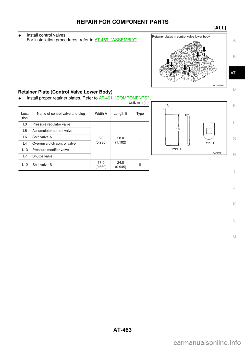
�Install control valves.
For installation procedures, refer to AT- 4 5 9 , "
ASSEMBLY" .
Retainer Plate (Control Valve Lower Body)
�Install proper retainer plates. Refer to AT- 4 6 1 , "COMPONENTS" .
Unit: mm (in)
SCIA4978E
Loca
tionName of control valve and plug Width A Length B Type
L3 Pressure regulator valve
6.0
(0.236)28.0
(1.102)I L5 Accumulator control valve
L6 Shift valve A
L4 Overrun clutch control valve
L13 Pressure modifier valve
L7 Shuttle valve
L12 Shift valve B17.0
(0.669)24.0
(0.945)II
SAT089F
Page 2763 of 4555
REPAIR FOR COMPONENT PARTS
AT-499
[ALL]
D
E
F
G
H
I
J
K
L
MA
B
AT
9. Remove spring retainer, O/D servo return spring, band servo
thrust washer and band servo piston stem from band servo pis-
ton.
10. Remove O-rings from servo piston retainer.
11. Remove D-rings from band servo piston.
INSPECTION
Pistons, Retainers and Piston Stem
�Check frictional surfaces for abnormal wear or damage.
Return Springs
�Check for deformation or damage.
�Measure the free length and outer diameter. Refer to AT- 5 3 8 ,
"Band Servo" .
SCIA4746E
SCIA3671E
SCIA3688E
AAT884
Page 2792 of 4555
![NISSAN X-TRAIL 2005 Service Repair Manual AT-528
[ALL]
ASSEMBLY
g. Tighten control valve assembly fixing bolts A , B and C to the specified torque. Refer to AT- 4 1 6 , "Compo-
nents" .
Bolt length, number and location:
CAUTION:
�Do not](/manual-img/5/57403/w960_57403-2791.png "NISSAN X-TRAIL 2005 Service Repair Manual AT-528
[ALL]
ASSEMBLY
g. Tighten control valve assembly fixing bolts A , B and C to the specified torque. Refer to AT- 4 1 6 , \"Compo-
nents\" .
Bolt length, number and location:
CAUTION:
�Do not")
AT-528
[ALL]
ASSEMBLY
g. Tighten control valve assembly fixing bolts A , B and C to the specified torque. Refer to AT- 4 1 6 , "Compo-
nents" .
Bolt length, number and location:
CAUTION:
�Do not reuse idler gear bearing.
�Apply ATF to idler gear bearing.
18. Install PNP switch.
a. Set manual shaft in “P” position.
b. Temporarily install PNP switch on manual shaft.
c. Move manual shaft to “N” position.
d. Use a 3 mm (0.12 in) pin for this adjustment.
i. Insert the pin straight into the manual shaft adjustment hole.
ii. Rotate PNP switch until the pin can also be inserted straight into
hole in PNP switch.
e. Tighten PNP switch fitting bolts. Refer to AT- 4 1 6 , "
Components"
.
f. Remove pin from adjustment hole after adjusting PNP switch.
19. Install bracket on transaxle case.
20. Install O-ring on revolution sensor.
CAUTION:
�Do not reuse O-ring.
�Apply petroleum jelly to O-ring.
21. Install revolution sensor on transaxle case.
Bolt symbol A B C
Bolt length “ ” mm (in)
40.0 mm
(1.575 in)33.0 mm
(1.299 in)43.5 mm
(1.713 in)
Number of bolts 5 6 2
AAT260A
SCIA3154E
SCIA4930E
Page 2795 of 4555
![NISSAN X-TRAIL 2005 Service Repair Manual SERVICE DATA AND SPECIFICATIONS (SDS)
AT-531
[ALL]
D
E
F
G
H
I
J
K
L
MA
B
AT
Stall RevolutionECS00CXM
Line PressureECS00F1T
Control ValvesECS00F1U
CONTROL VALVE AND PLUG RETURN SPRINGS
For 85X23 mod](/manual-img/5/57403/w960_57403-2794.png "NISSAN X-TRAIL 2005 Service Repair Manual SERVICE DATA AND SPECIFICATIONS (SDS)
AT-531
[ALL]
D
E
F
G
H
I
J
K
L
MA
B
AT
Stall RevolutionECS00CXM
Line PressureECS00F1T
Control ValvesECS00F1U
CONTROL VALVE AND PLUG RETURN SPRINGS
For 85X23 mod")
SERVICE DATA AND SPECIFICATIONS (SDS)
AT-531
[ALL]
D
E
F
G
H
I
J
K
L
MA
B
AT
Stall RevolutionECS00CXM
Line PressureECS00F1T
Control ValvesECS00F1U
CONTROL VALVE AND PLUG RETURN SPRINGS
For 85X23 model
Unit: mm (in)
*: Always check with the Parts Department for the latest parts information.EngineStall revolution
rpm
QR20DE 2,450 - 2,950
QR25DE 2,300 - 2,750
Engine speed
rpmLine pressure kPa (kg/cm2 , psi)
D, 2 and 1 positions R position
Idle 500 (5.1, 73) 778 (7.9, 113)
Stall 1,233 (12.6, 179) 1,918 (19.6, 278)
PartsItem
Part No.* Free length Outer diameter
Upper body7 Pilot valve spring 31742-3AX03 38.98 (1.535) 8.9 (0.350)
35 1-2 accumulator valve spring 31742-3AX00 20.5 (0.807) 6.95 (0.274)
10 1-2 accumulator piston spring 31742-85X02 55.60 (2.189) 19.6 (0.772)
17 1st reducing valve spring 31742-80X05 27.0 (1.063) 7.0 (0.276)
19 3-2 timing valve spring 31736-01X00 23.0 (0.906) 6.65 (0.262)
24 Overrun clutch reducing valve spring 31742-80X15 37.5 (1.476) 6.9 (0.272)
26 Torque converter relief valve spring 31742-80X07 31.0 (1.220) 9.0 (0.354)
31 Torque converter clutch control valve 31742-85X00 56.98 (2.243) 6.5 (0.256)
3 Cooler check valve spring 31742-85X01 29.4 (1.157) 6.0 (0.236)
Lower body11 Pressure regulator valve spring 31742-80X13 45.0 (1.772) 15.0 (0.591)
16 Overrun clutch control valve spring 31762-80X00 21.7 (0.854) 7.0 (0.276)
20 Accumulator control valve spring 31742-80X02 22.0 (0.866) 6.5 (0.256)
25 Shift valve A spring 31762-80X00 21.7 (0.854) 7.0 (0.276)
30 Shuttle valve spring 31762-41X04 51.0 (2.008) 5.65 (0.222)
32 Shift valve B spring 31762-80X00 21.7 (0.854) 7.0 (0.276)
2 Pressure modifier piston spring 31742-41X15 30.5 (1.201) 9.8 (0.386)
6 Pressure modifier valve spring 31742-80X16 32.0 (1.260) 6.9 (0.272)
— Oil cooler relief valve spring 31872-31X00 17.02 (0.670) 8.0 (0.315)
Page 2796 of 4555
![NISSAN X-TRAIL 2005 Service Repair Manual AT-532
[ALL]
SERVICE DATA AND SPECIFICATIONS (SDS)
For 85X64 model
Unit: mm (in)
*: Always check with the Parts Department for the latest parts information.
AccumulatorECS00F1V
O-RING
Unit: mm (in)](/manual-img/5/57403/w960_57403-2795.png "NISSAN X-TRAIL 2005 Service Repair Manual AT-532
[ALL]
SERVICE DATA AND SPECIFICATIONS (SDS)
For 85X64 model
Unit: mm (in)
*: Always check with the Parts Department for the latest parts information.
AccumulatorECS00F1V
O-RING
Unit: mm (in)")
AT-532
[ALL]
SERVICE DATA AND SPECIFICATIONS (SDS)
For 85X64 model
Unit: mm (in)
*: Always check with the Parts Department for the latest parts information.
AccumulatorECS00F1V
O-RING
Unit: mm (in)
*: Always check with the Parts Department for the latest parts information.PartsItem
Part No.* Free length Outer diameter
Upper body7 Pilot valve spring 31742-3AX03 38.98 (1.535) 8.9 (0.350)
35 1-2 accumulator valve spring 31742-3AX00 20.5 (0.807) 6.95 (0.274)
10 1-2 accumulator piston spring 31742-3AX08 55.26 (2.176) 19.6 (0.772)
17 1st reducing valve spring 31742-80X05 27.0 (1.063) 7.0 (0.276)
19 3-2 timing valve spring 31736-01X00 23.29 (0.917) 6.65 (0.262)
24 Overrun clutch reducing valve spring 31742-80X15 37.5 (1.476) 6.9 (0.272)
26 Torque converter relief valve spring 31742-80X07 31.0 (1.220) 9.0 (0.354)
31 Torque converter clutch control valve spring 31742-85X00 56.98 (2.243) 6.5 (0.256)
3 Cooler check valve spring 31742-85X01 29.4 (1.157) 6.0 (0.236)
Lower body11 Pressure regulator valve spring 31742-80X13 45.0 (1.772) 15.0 (0.591)
16 Overrun clutch control valve spring 31762-80X00 21.7 (0.854) 7.0 (0.276)
20 Accumulator control valve spring 31742-80X02 22.0 (0.866) 6.5 (0.256)
25 Shift valve A spring 31762-80X00 21.7 (0.854) 7.0 (0.276)
30 Shuttle valve spring 31762-41X04 51.0 (2.008) 5.65 (0.222)
32 Shift valve B spring 31762-80X00 21.7 (0.854) 7.0 (0.276)
2 Pressure modifier piston spring 31742-41X15 30.5 (1.201) 9.8 (0.386)
6 Pressure modifier valve spring 31742-80X16 32.0 (1.260) 6.9 (0.272)
— Oil cooler relief valve spring 31872-31X00 17.02 (0.670) 8.0 (0.315)
Accumulator Part No.*Inner diameter
(Small)Part No.*Inner diameter
(Large)
Servo release accumulator 31526 41X03 26.9 (1.059) 31526 41X02 44.2 (1.740)
N-D accumulator 31526 31X08 34.6 (1.362) 31672 21X00 39.4 (1.551)
Page 2797 of 4555
![NISSAN X-TRAIL 2005 Service Repair Manual SERVICE DATA AND SPECIFICATIONS (SDS)
AT-533
[ALL]
D
E
F
G
H
I
J
K
L
MA
B
AT
RETURN SPRING
Unit: mm (in)
*: Always check with the Parts Department for the latest parts information.
Clutch and Brakes](/manual-img/5/57403/w960_57403-2796.png "NISSAN X-TRAIL 2005 Service Repair Manual SERVICE DATA AND SPECIFICATIONS (SDS)
AT-533
[ALL]
D
E
F
G
H
I
J
K
L
MA
B
AT
RETURN SPRING
Unit: mm (in)
*: Always check with the Parts Department for the latest parts information.
Clutch and Brakes")
SERVICE DATA AND SPECIFICATIONS (SDS)
AT-533
[ALL]
D
E
F
G
H
I
J
K
L
MA
B
AT
RETURN SPRING
Unit: mm (in)
*: Always check with the Parts Department for the latest parts information.
Clutch and BrakesECS00F1W
REVERSE CLUTCH
*: Always check with the Parts Department for the latest parts information.
HIGH CLUTCH
*: Always check with the Parts Department for the latest parts information.
FORWARD CLUTCH
Accumulator Part number* Free length Outer diameter
Servo release accumulator 31605-80X00 52.5 (2.067) 20.1 (0.791)
N-D accumulator 31605-31X15 43.5 (1.713) 28.0 (1.102)
Model code number85X23, 85X64
Number of drive plates2
Number of driven plates2
Drive plate thickness mm (in)Standard 1.6 (0.063)
Wear limit 1.4 (0.055)
Driven plate thickness mm (in) Standard 1.8 (0.071)
Clearance mm (in)Standard 0.5 - 0.8 (0.020 - 0.031)
Wear limit 1.2 (0.047)
Thickness of retaining platesThickness mm (in) Part number*
6.6 (0.260)
6.8 (0.268)
7.0 (0.276)
7.2 (0.283)
7.4 (0.291)
7.6 (0.299)
7.8 (0.307)31537-80X05
31537-80X06
31537-80X07
31537-80X08
31537-80X09
31537-80X20
31537-80X21
Model code number85X23, 85X64
Number of drive plates3
Number of driven plates
7*
1 + 1*2
Drive plate
thickness mm (in)Standard 1.6 (0.063)
Wear limit 1.4 (0.055)
Driven plate
thickness mm (in)*1 Standard 1.4 (0.055)
*2 Standard 2.0 (0.079)
Clearance mm (in)Standard 1.8 - 2.2 (0.071 - 0.087)
Wear limit 2.8 (0.110)
Thickness of retaining platesThickness mm (in) Part number*
3.2 (0.126)
3.4 (0.134)
3.6 (0.142)
3.8 (0.150)
4.0 (0.157)31537-81X11
31537-81X12
31537-81X13
31537-81X14
31537-81X15
Model code number85X23
Number of drive plates4
Number of driven plates4
Drive plate thickness mm (in)Standard 1.6 (0.063)
Wear limit 1.4 (0.055)
![NISSAN X-TRAIL 2005 Service Repair Manual REPAIR FOR COMPONENT PARTS
AT-499
[ALL]
D
E
F
G
H
I
J
K
L
MA
B
AT
9. Remove spring retainer, O/D servo return spring, band servo
thrust washer and band servo piston stem from band servo pis-
ton.
10](/manual-img/5/57403/w960_57403-2762.png "NISSAN X-TRAIL 2005 Service Repair Manual REPAIR FOR COMPONENT PARTS
AT-499
[ALL]
D
E
F
G
H
I
J
K
L
MA
B
AT
9. Remove spring retainer, O/D servo return spring, band servo
thrust washer and band servo piston stem from band servo pis-
ton.
10")