Page 2961 of 4555
 shown
in the figure.
CAUTION:
If there is grease on boot mounting surfaces (indicated")
REAR DRIVE SHAFT
RAX-17
C
E
F
G
H
I
J
K
L
MA
B
RAX
7. Install boot securely into grooves (indicated by * marks) shown
in the figure.
CAUTION:
If there is grease on boot mounting surfaces (indicated by *
marks) of joint, boot may come off. Remove all grease from
surfaces.
8. Check that boot installation length “L” is the length indicated
below. Insert a flat-bladed screwdriver or similar tool into smaller
side of boot. Remove air from boot to prevent boot deformation.
CAUTION:
�Boot may break if boot installation length is less than
standard value.
�Be careful that screwdriver tip does not contact inside
surface of boot.
9. Secure big and small ends of boot with new boot bands as
shown in figure.
CAUTION:
Rotate housing and check that boot installation position
does not change. If position changes, reinstall boot bands.
Wheel Side
1. Use a drift (SST) to press-fit sensor rotor into joint sub-assem-
bly.
CAUTION:
Discard the old sensor rotor; replace with a new one.
SDIA0599E
Boot installation length:
78.6 - 80.6 mm (3.094 - 3.173 in)
SDIA0600E
SFA395
SDIA0602E
Page 2962 of 4555

RAX-18
REAR DRIVE SHAFT
2. Wind serrated part of drive shaft with tape. Install boot band and
boot to shaft. Be careful not to damage boot.
CAUTION:
Discard the old boot band and boot; replace with new ones.
3. Remove protective tape wound around serrated part of shaft.
4. Attach circular clip to shaft. At this time, circular clip must fit
securely into the shaft groove. Attach nut to joint sub-assembly.
Use a wooden hammer to press-fit.
CAUTION:
Discard the old circular clip; replace with a new one.
5. Insert the amount of grease (Nissan genuine grease or equiva-
lent) listed below into housing from large end of boot.
6. Install boot securely into grooves (indicated by * marks) shown
in the figure.
CAUTION:
If there is grease on boot mounting surfaces (indicated by *
marks) of joint sub-assembly, boot may come off. Remove
all grease from surfaces.
7. Check that boot installation length “L” is the length indicated
below. Insert a flat-bladed screwdriver or similar tool into smaller
side of boot. Remove air from boot to prevent boot deformation.
CAUTION:
�Boot may break if boot installation length is less than standard value.
�Be careful that screwdriver tip does not contact inside surface of boot.
8. Secure big and small ends of boot with new boot bands as
shown in the figure.
CAUTION:
Rotate housing and check that boot installation position
does not change. If position changes, reinstall boot bands.
SDIA0597E
Grease amount : 35 - 45 g (1.23 - 1.59 oz)
RAC0049D
Boot installation length:
66.7 - 68.7 mm (2.626 - 2.705 in)SDIA0607E
SFA395
Page 2963 of 4555
SERVICE DATA AND SPECIFICATIONS (SDS)
RAX-19
C
E
F
G
H
I
J
K
L
MA
B
RAX
SERVICE DATA AND SPECIFICATIONS (SDS)PFP:00030
Wheel BearingEDS000ID
Drive ShaftEDS000IE
Rotation torque 1.96 N·m (0.20 kg-m, 17 in-lb) or less
Spring balance reading 12.8 N (1.30 kg) or less
Installation location of spring balance mm (in)
Axial end play 0.05 mm (0.0020 in) or less
SDIA0148E
Specified amount of greaseFinal drive side 40 - 50 g (1.41 - 1.77 oz)
Wheel side 35 - 45 g (1.23 - 1.59 oz)
Boot lengthFinal drive side (L
2 ) 78.6 - 80.6 mm (3.094 - 3.173 in)
Wheel side (L
1 ) 66.7 - 68.7 mm (2.626 - 2.705 in)
SDIA0618E
Page 3022 of 4555
BR-24
BRAKE BOOSTER
INSPECTION AFTER REMOVAL
Output rod length inspection
1. Using a handy vacuum pump, apply a vacuum of -66.7 kPa (-500 mmHg, -19.69 inHg) to the brake
booster.
2. Check output rod length.
3.
INSTALLATION
1. Loosen lock nut to adjust input rod length so that length “B” (in
the figure) satisfies the specified value.
2. After adjusting “B”, temporarily tighten lock nut to install booster
assembly to vehicle.
3. Connect brake pedal to input rod clevis.
4. Connect brake pedal assembly mounting nuts and tighten to the
specified torque.
5. Connect master cylinder to booster assembly.
6. Adjust brake pedal height and play.
7. Tighten input rod lock nut to the specified torque.
8. Bleed air. Refer to BR-9, "
Bleeding Brake System" . Reference value at vacuum of –66.7 kPa (–500 mmHg,
–19.69 inHg):
Without ESP models : 10.4 mm (0.409 in)
With ESP models : -6.2 mm (-0.244 in)
SBR208E
Length “B” standard : 125 mm (4.92 in)
SGIA0060E
Page 3036 of 4555

SERVICE DATA AND SPECIFICATIONS (SDS)PFP:00030
General SpecificationsEFS000CQ
Unit: mm (in)
Brake PedalEFS000CR
Check ValveEFS000CS
Brake BoosterEFS000CT")
BR-38
SERVICE DATA AND SPECIFICATIONS (SDS)
SERVICE DATA AND SPECIFICATIONS (SDS)PFP:00030
General SpecificationsEFS000CQ
Unit: mm (in)
Brake PedalEFS000CR
Check ValveEFS000CS
Brake BoosterEFS000CT
Vacuum type
Front Disc BrakeEFS000CU
Front brakeBrake model AD31VD
Cylinder bore diameter 44.4 × 2 (1.748 × 0.08)
Pad
Length x width x thickness132.0 × 52.5 × 11.0
(5.20 × 2.067 × 0.433)
Rotor outer diameter x thickness 280 × 28 (11.02 × 1.10)
Rear brakeBrake model AD9VA
Cylinder bore diameter 34.9 (1.374)
Pad
Length x width x thickness83.0 × 33.0 × 8.5
(3.268 × 1.299 × 0.335)
Rotor outer diameter x thickness 292 × 16 (11.50 × 0.63)
Master cylinder Cylinder bore diameter 25.4 (1)
Control valve Valve model Electronic control type
Brake boosterBooster model C215T
Diaphragm diameterPrimary 230 (9.06)
Secondary 205 (8.07)
Recommended brake fluid DOT 3 or DOT 4
Pedal play3 - 11 mm (0.12 - 0.43 in)
Looseness at clevis pin 1 - 3 mm (0.04 - 0.12 in)
Brake pedal height (from dash panel top surface)M/T model 156 - 166 mm (6.14 - 6.54 in)
A/T model 164 - 174 mm (6.46 - 6.85 in)
Depressed pedal height under a force of 490 N (50 kg,110.6 lb)
(from dash panel top surface)M/T model 80 mm (3.15 in) or more
A/T model 85 mm (3.35 in) or more
Clearance between threaded end of stop lamp switch and pedal stopper 0.74 - 1.96 mm (0.0291 - 0.0772 in)
Vacuum leakage [at vacuum of 66.7 kPa (-500 mmHg, -19.69
inHg)]Within 1.3 kPa (10 mmHg, 0.39 inHg) of vacuum for 15 seconds
Vacuum leakage [at vacuum of -66.7 kPa (-500 mmHg, -19.69
inHg)]Within 3.3 kPa (25 mmHg, 0.98 inHg) of vacuum for 15 seconds
Input rod installation standard dimension 125 mm (4.92 in)
Brake typeAD31VD
Brake padStandard thickness (new) 11 mm (0.43 in)
Repair limit thickness 2.0 mm (0.079 in)
Disc rotorStandard thickness (new) 28.0 mm (1.102 in)
Repair limit thickness 26.0 mm (1.024 in)
Runout limit 0.04 mm (0.0016 in)
Page 3475 of 4555
STEERING COLUMN
PS-13
C
D
E
F
H
I
J
K
L
MA
B
PS
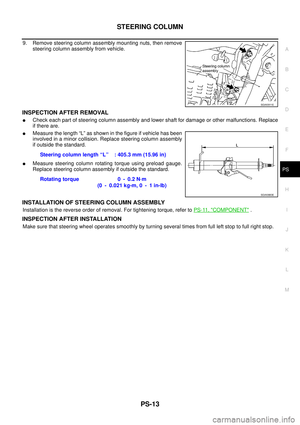
9. Remove steering column assembly mounting nuts, then remove
steering column assembly from vehicle.
INSPECTION AFTER REMOVAL
�Check each part of steering column assembly and lower shaft for damage or other malfunctions. Replace
if there are.
�Measure the length “L” as shown in the figure if vehicle has been
involved in a minor collision. Replace steering column assembly
if outside the standard.
�Measure steering column rotating torque using preload gauge.
Replace steering column assembly if outside the standard.
INSTALLATION OF STEERING COLUMN ASSEMBLY
Installation is the reverse order of removal. For tightening torque, refer to PS-11, "COMPONENT" .
INSPECTION AFTER INSTALLATION
Make sure that steering wheel operates smoothly by turning several times from full left stop to full right stop.
SGIA0911E
Steering column length “L” : 405.3 mm (15.96 in)
Rotating torque 0 - 0.2 N·m
(0 - 0.021 kg-m, 0 - 1 in-lb)
SGIA0883E
Page 3487 of 4555

POWER STEERING GEAR AND LINKAGE
PS-25
C
D
E
F
H
I
J
K
L
MA
B
PS
18. Set dial gauge as shown in the figure. Measure vertical move-
ment of rack assembly when pinion is turned clockwise with
torque of 4.9 N·m (0.5 kg-m, 43 in-lb). Readjust adjusting screw
angle if the measured value is outside the standard. Replace
gear assembly if the measured value is still outside the standard
or adjusting screw rotating torque is 4.9 N·m (0.5 kg-m, 43 in-lb)
or less.
19. Install large end of boot to gear housing assembly.
20. Install small end of boot to inner socket boot mounting groove.
21. Install boot clamp to boot small end.
22. Install large side of boot clamp.
NOTE:
Do not reuse large side of boot clamp.
�Tighten large side of boot with boot clamp (stainless wire).
�Wrap clamp around boot groove for two turns. Insert a flat-
bladed screwdriver in loops on both ends of wire. Twist 4 to
4.5 turns while pulling them with force of approximately 98 N
(10 kg, 22 lb).
�Twist boot clamp as shown. Pay attention to relationship
between winding and twisting directions.
SGIA0465E
Vertical movement of rack 0.265 mm (0.0104 in) or less
Measuring pointRack axial direction 5 mm (0.197 in) from housing end surface
Rack radial direction Axial direction of the adjusting screw
SGIA0550E
Wire length “L” : 370 mm (14.57 in)
SGIA0163E
SGIA0164E
Page 3488 of 4555
PS-26
POWER STEERING GEAR AND LINKAGE
�Twisted point of clamp is in the opposite side of adjusting
screw as shown in the figure (to prevent contact with other
parts).
�Bent cut end of the wire toward rack axial as shown in the fig-
ure after twisting the wire 4 to 4.5 turns so that cut end does
not contact with boot.
CAUTION:
Keep gap from cylinder tube 5 mm (0.20 in) or more.
23. Install cylinder tube to gear housing assembly.
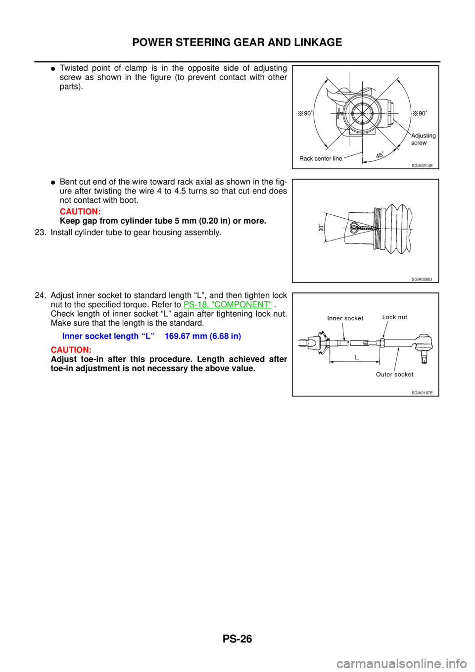
24. Adjust inner socket to standard length “L”, and then tighten lock
nut to the specified torque. Refer to PS-18, "
COMPONENT" .
Check length of inner socket “L” again after tightening lock nut.
Make sure that the length is the standard.
CAUTION:
Adjust toe-in after this procedure. Length achieved after
toe-in adjustment is not necessary the above value.
SGIA0214E
SGIA0260J
Inner socket length “L” 169.67 mm (6.68 in)
SGIA0167E

RAX-19
C
E
F
G
H
I
J
K
L
MA
B
RAX
SERVICE DATA AND SPECIFICATIONS (SDS)PFP:00030
Wheel BearingEDS000ID
Drive ShaftEDS000IE
Rotation torque 1.96 N·m (0.20 kg-m,")
 to the brake
booster.
2. Check output rod")