Page 202 of 4555
EM-148
[YD22DDTi]
INTAKE MANIFOLD
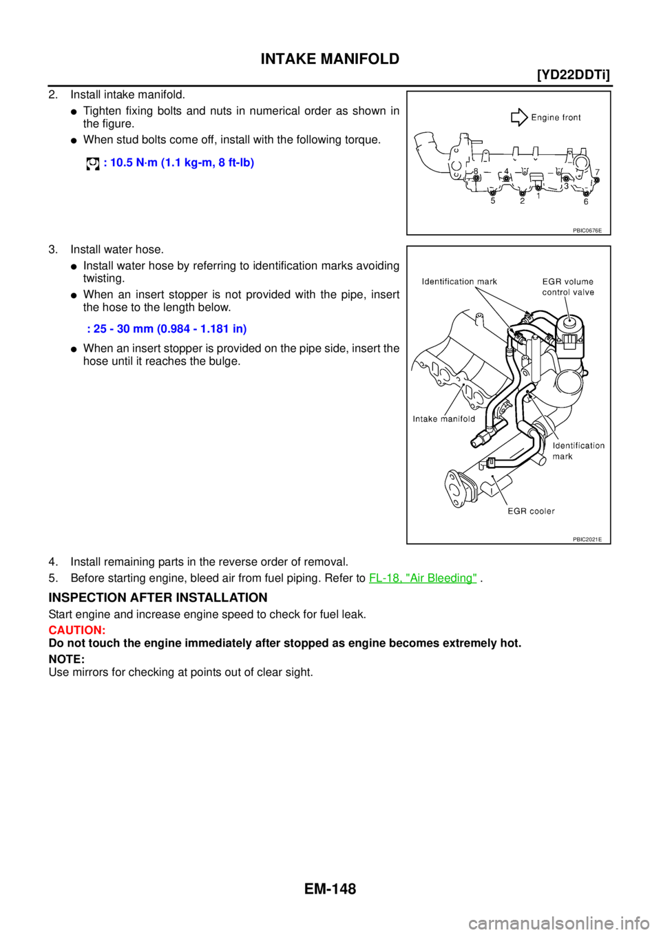
2. Install intake manifold.
�Tighten fixing bolts and nuts in numerical order as shown in
the figure.
�When stud bolts come off, install with the following torque.
3. Install water hose.
�Install water hose by referring to identification marks avoiding
twisting.
�When an insert stopper is not provided with the pipe, insert
the hose to the length below.
�When an insert stopper is provided on the pipe side, insert the
hose until it reaches the bulge.
4. Install remaining parts in the reverse order of removal.
5. Before starting engine, bleed air from fuel piping. Refer to FL-18, "
Air Bleeding" .
INSPECTION AFTER INSTALLATION
Start engine and increase engine speed to check for fuel leak.
CAUTION:
Do not touch the engine immediately after stopped as engine becomes extremely hot.
NOTE:
Use mirrors for checking at points out of clear sight. : 10.5 N·m (1.1 kg-m, 8 ft-lb)
PBIC0676E
: 25 - 30 mm (0.984 - 1.181 in)
PBIC2021E
Page 214 of 4555
![NISSAN X-TRAIL 2005 Service Repair Manual EM-160
[YD22DDTi]
OIL PAN AND OIL STRAINER
�Tighten bolts in numerical order to the specified torque.
�Bolt dimensions vary depending on the installation location.
Refer to the following and use app](/manual-img/5/57403/w960_57403-213.png "NISSAN X-TRAIL 2005 Service Repair Manual EM-160
[YD22DDTi]
OIL PAN AND OIL STRAINER
�Tighten bolts in numerical order to the specified torque.
�Bolt dimensions vary depending on the installation location.
Refer to the following and use app")
EM-160
[YD22DDTi]
OIL PAN AND OIL STRAINER
�Tighten bolts in numerical order to the specified torque.
�Bolt dimensions vary depending on the installation location.
Refer to the following and use appropriate bolts.
�The shank length under the bolt neck above is the length of
the threaded part (pilot portion not included).
2. Install oil strainer.
3. Tighten transaxle joint bolts.
4. Install rear plate cover.
5. Install center member. Refer to EM-222, "
ENGINE ASSEMBLY" .
6. Install crankshaft position sensor.
7. Install oil pan lower as follows:
a. Use a scraper to remove old liquid gasket from mating surfaces.
CAUTION:
�Also remove old liquid gasket from mating surface of oil
pan upper.
�Remove old liquid gasket from bolt hole and thread.
b. Apply a continuous bead of liquid gasket with the tube presser
(special service tool: WS39930000) as shown in the figure.
Use Genuine Liquid Gasket or equivalent.
�Be sure liquid gasket is 3.5 to 4.5 mm (0.138 to 0.177 in)
wide.
�Attaching should be done within 5 minutes after coating.M6 x 30 mm (1.18 in) : Bolt No. 15, 16
M8 x 25 mm (0.98 in) : Bolt No. 3, 4, 9, 10
M8 x 60 mm (2.36 in) : Bolt No. 1, 2, 5, 6, 7, 8,
11, 12, 13, 14
SBIA0162E
PBIC2277E
SBIA0163E
SBIA0164E
Page 227 of 4555
![NISSAN X-TRAIL 2005 Service Repair Manual FUEL PUMP
EM-173
[YD22DDTi]
C
D
E
F
G
H
I
J
K
L
MA
EM
14. Using the sprocket holder (special service tool), hold fuel pump
sprocket to prevent falling.
�For sprocket holder, use KV11106060 machined](/manual-img/5/57403/w960_57403-226.png "NISSAN X-TRAIL 2005 Service Repair Manual FUEL PUMP
EM-173
[YD22DDTi]
C
D
E
F
G
H
I
J
K
L
MA
EM
14. Using the sprocket holder (special service tool), hold fuel pump
sprocket to prevent falling.
�For sprocket holder, use KV11106060 machined")
FUEL PUMP
EM-173
[YD22DDTi]
C
D
E
F
G
H
I
J
K
L
MA
EM
14. Using the sprocket holder (special service tool), hold fuel pump
sprocket to prevent falling.
�For sprocket holder, use KV11106060 machined as shown in
the figure, because the previous bore is not fitting.
�When the sprocket holder is installed, if the positioning stop-
per pin (special service tool) interferes, pull out the positioning
stopper pin approximately 10 mm (0.39 in), then install it.
�After the sprocket holder is installed temporarily, tighten the
sprocket holder after making extension bar and TORX socket
(size: E10) insert into the machined bore.
�The length of the sprocket holder mounting bolts should be
approximately 15 mm (0.59 in) (M6 thread length).
�Make sure that the a- and b-faces of the sprocket holder con-
tact the bottom side of the sprocket (small diameter side).
CAUTION:
Do not remove the sprocket holder (special service tool) until fuel pump is installed.
�After the sprocket holder is installed, pull out the positioning
stopper pin from fuel pump sprocket.
MBIA0074E
SBIA0217E
PBIC2534E
MBIA0075E
Page 254 of 4555
![NISSAN X-TRAIL 2005 Service Repair Manual EM-200
[YD22DDTi]
PRIMARY TIMING CHAIN
REMOVAL
1. Remove engine coolant reservoir tank. Refer to CO-35, "RADIATOR" .
2. Remove charge air cooler. Refer to EM-144, "
Removal and Installation" .
3. Re](/manual-img/5/57403/w960_57403-253.png "NISSAN X-TRAIL 2005 Service Repair Manual EM-200
[YD22DDTi]
PRIMARY TIMING CHAIN
REMOVAL
1. Remove engine coolant reservoir tank. Refer to CO-35, \"RADIATOR\" .
2. Remove charge air cooler. Refer to EM-144, \"
Removal and Installation\" .
3. Re")
EM-200
[YD22DDTi]
PRIMARY TIMING CHAIN
REMOVAL
1. Remove engine coolant reservoir tank. Refer to CO-35, "RADIATOR" .
2. Remove charge air cooler. Refer to EM-144, "
Removal and Installation" .
3. Remove air cleaner and air duct. Refer to EM-142, "
Removal and Installation" .
4. Remove rocker cover. Refer to EM-178, "
Removal and Installation" .
5. Remove RH engine mounting insulator and bracket. Refer to EM-222, "
ENGINE ASSEMBLY" .
6. Pull power steering reservoir tank out of brackets to move power steering piping. Refer to PS-37,
"HYDRAULIC LINE" .
CAUTION:
To avoid removing power steering reservoir tank out of brackets move it with power steering pip-
ing aside.
7. Remove oil pan (upper and lower). Refer to EM-157, "
Removal and Installation" .
8. Remove oil filter bracket. Refer to LU-26, "
OIL FILTER BRACKET" .
9. Remove fuel injector. Refer to EM-167, "
Removal and Installation" .
10. Remove secondary timing chain and associated parts. Refer to EM-193, "
Removal and Installation" .
11. When removing rear chain case, remove camshaft sprockets. Refer to EM-180, "
Removal and Installa-
tion" .
12. Remove crankshaft pulley as follows:
a. Hold crankshaft pulley with the pulley holder (special service
tool).
b. Loosen crankshaft pulley fixing bolt and pull out the bolt approx-
imately 10 mm (0.39 in).
c. Using the pulley puller (special service tool), remove crankshaft
pulley.
�Use two M6 bolts with approx. 60 mm (2.36 in) shank length
for securing crankshaft pulley.
13. Remove oil pump housing.
10. O-ring 11. Chain guide 12. Tension guide
13. Spacer 14. Gasket 15. Front chain case
16. Rubber washer 17. Crankshaft pulley 18. Front oil seal
19. Power steering oil pump cover 20. Oil pump housing 21. Primary timing chain
22. Oil pump drive spacer 23. Crankshaft sprocket 24. Secondary timing chain
25. Rear chain case 26. Power steering oil pump 27. Key
JEM131G
JEM132G
Page 259 of 4555
![NISSAN X-TRAIL 2005 Service Repair Manual PRIMARY TIMING CHAIN
EM-205
[YD22DDTi]
C
D
E
F
G
H
I
J
K
L
MA
EM
d. Tighten bolts in numerical order shown in the figure.
�Install the following four types of bolts, referring to the figure.
�The sh](/manual-img/5/57403/w960_57403-258.png "NISSAN X-TRAIL 2005 Service Repair Manual PRIMARY TIMING CHAIN
EM-205
[YD22DDTi]
C
D
E
F
G
H
I
J
K
L
MA
EM
d. Tighten bolts in numerical order shown in the figure.
�Install the following four types of bolts, referring to the figure.
�The sh")
PRIMARY TIMING CHAIN
EM-205
[YD22DDTi]
C
D
E
F
G
H
I
J
K
L
MA
EM
d. Tighten bolts in numerical order shown in the figure.
�Install the following four types of bolts, referring to the figure.
�The shank length under the bolt neck above is the length of
threaded part (pilot portion not included).
e. After tightening all the bolts, re-tighten in the same order.
2. Install power steering oil pump.
3. Install fuel pump. Refer to EM-171, "
FUEL PUMP" .
�Before installing, make sure that spacer and the hole 6 mm
(0.24 in) in diameter on coupling are aligned.
4. Install chain guide and tension guides.
5. Install crankshaft sprocket, aligning it with crankshaft key on the
far side.
6. Install primary timing chain with fuel pump sprocket.
�When installing, match the alignment marks on sprockets with
color coded alignment marks (colored links) on primary timing
chain.
�Install fuel pump sprocket washer with the surface marked “F”
(front mark) facing the front of the engine.
7. Install timing chain onto power steering oil pump sprocket and
through chain guide.
8. Use the positioning stopper pin (special service tool) to hold the
fuel pump sprocket and install the bolt.
�Using the TORX wrench (special service tool), turn the fuel
pump shaft little by little to adjust the position of the fuel pump
sprocket. Insert positioning stopper pin into the hole 6 mm
(0.24 in) in diameter on fuel pump sprocket so that the stop-
per pin goes through the fuel pump body. While the stopper
pin is in place, install the bolt.16 mm (0.63 in) : Bolt No. 1, 2, 16, 17, 18, 19, 20, 21, 22
20 mm (0.79 in) : Bolt No. 3, 4, 6, 9, 10, 11, 13, 14
25 mm (0.98 in) : Bolt No. 12, 15
35 mm (1.38 in) : Bolt No. 5, 7, 8
SBIA0211E
PBIC2498E
MBIA0079E
MBIA0049E
Page 273 of 4555
![NISSAN X-TRAIL 2005 Service Repair Manual CYLINDER HEAD
EM-219
[YD22DDTi]
C
D
E
F
G
H
I
J
K
L
MA
EM
5. Using the valve guide drift (commercial service tool), press fit
valve guides from camshaft side, referring to the dimension
shown in the](/manual-img/5/57403/w960_57403-272.png "NISSAN X-TRAIL 2005 Service Repair Manual CYLINDER HEAD
EM-219
[YD22DDTi]
C
D
E
F
G
H
I
J
K
L
MA
EM
5. Using the valve guide drift (commercial service tool), press fit
valve guides from camshaft side, referring to the dimension
shown in the")
CYLINDER HEAD
EM-219
[YD22DDTi]
C
D
E
F
G
H
I
J
K
L
MA
EM
5. Using the valve guide drift (commercial service tool), press fit
valve guides from camshaft side, referring to the dimension
shown in the figure.
CAUTION:
Cylinder head contains heat, when working, wear protective
equipment to avoid getting burned.
6. Using the valve guide reamer (commercial service tool), perform
reaming to the press-fitted valve guides.
Valve Seat Contact
�Before starting this check, confirm that the dimension of valve
guide and valves are as specified.
�Apply red lead primer on contacting surfaces of valves seat and
of valve face to examine the conditions of contacting surfaces.
�Make sure that the paint on contacting surfaces is continuous
along the entire circumference.
�If there are abnormal indications, grind the valve and check the
contact again. If malfunction indications still persist, replace
valve seat. Refer to EM-219, "
Valve Seat Replacement" .
Valve Seat Replacement
When removing valve seat, replace it with oversized [0.5 mm (0.020 in)] valve seat.
1. Bore out old seat until it collapses. Boring should not continue beyond the bottom face of the seat recess
in cylinder head. Set the machine depth stop to ensure this. Refer to EM-261, "
Va l v e S e a t" .
2. Ream cylinder head recess diameter for service valve seat.
�Be sure to ream in circles concentric to the valve guide center.
�This will enable valve seat to fit correctly.Projection length “H” : 10.4 - 10.6 mm (0.409 - 0.417 in)
PBIC2187E
Standard
Intake and Exhaust:
6.000 - 6.018 mm (0.2362 - 0.2369 in)
SEM932C
SBIA0322E
Oversize [0.5 mm (0.020 in)]:
Intake : 30.500 - 30.516 mm (1.2008 - 1.2014 in)
Exhaust : 29.500 - 29.516 mm (1.1614 - 1.1620 in)
SEM795A
Page 313 of 4555
SERVICE DATA AND SPECIFICATIONS (SDS)
EM-259
[YD22DDTi]
C
D
E
F
G
H
I
J
K
L
MA
EM
CYLINDER HEAD
Unit: mm (in)
VA LV E
Valve Dimensions
Unit: mm (in) Item Standard Limit
Cylinder head distortion Less than 0.03 (0.0012) 0.1 (0.004)
JEM204G
Valve head diameter “D”Intake 28.0 - 28.3 (1.102 - 1.114)
Exhaust 26.0 - 26.3 (1.024 - 1.035)
Valve length “L”Intake 106.72 (4.2016)
Exhaust 106.36 (4.1874)
Valve stem diameter “d”Intake 5.965 - 5.980 (0.2348 - 0.2354)
Exhaust 5.945 - 5.960 (0.2341 - 0.2346)
Valve seat angle “α”Intake
45 degrees 15′ - 45 degrees 45′
Exhaust
Valve margin “T”Intake 1.38 (0.0543)
Exhaust 1.48 (0.0583)
Valve margin “T” limitMore than 1.0 (0.039)
Valve stem end surface grinding limit Less than 0.2 (0.008)
SEM188
Page 314 of 4555
EM-260
[YD22DDTi]
SERVICE DATA AND SPECIFICATIONS (SDS)
Valve Guide
Unit: mm (in)
Item Standard Service
Valve guide Outer diameter 10.023 - 10.034 (0.3946 - 0.3950) 10.223 - 10.234 (0.4025 - 0.4029)
Valve guide Inner diameter (Finished size) 6.000 - 6.018 (0.2362 - 0.2369)
Cylinder head valve guide hole diameter 9.975 - 9.996 (0.3927 - 0.3935) 10.175 - 10.196 (0.4006 - 0.4014)
Interference fit of valve guide 0.027 - 0.059 (0.0011 - 0.0023)
Item Standard Limit
Valve guide clearanceIntake 0.020 - 0.053 (0.0008 - 0.0021) 0.08 (0.0031)
Exhaust 0.040 - 0.073 (0.0016 - 0.0029) 0.10 (0.0039)
Projection length 10.4 - 10.6 (0.409 - 0.417)
JEM156G
![NISSAN X-TRAIL 2005 Service Repair Manual SERVICE DATA AND SPECIFICATIONS (SDS)
EM-259
[YD22DDTi]
C
D
E
F
G
H
I
J
K
L
MA
EM
CYLINDER HEAD
Unit: mm (in)
VA LV E
Valve Dimensions
Unit: mm (in) Item Standard Limit
Cylinder head distortion Less](/manual-img/5/57403/w960_57403-312.png "NISSAN X-TRAIL 2005 Service Repair Manual SERVICE DATA AND SPECIFICATIONS (SDS)
EM-259
[YD22DDTi]
C
D
E
F
G
H
I
J
K
L
MA
EM
CYLINDER HEAD
Unit: mm (in)
VA LV E
Valve Dimensions
Unit: mm (in) Item Standard Limit
Cylinder head distortion Less")
![NISSAN X-TRAIL 2005 Service Repair Manual EM-260
[YD22DDTi]
SERVICE DATA AND SPECIFICATIONS (SDS)
Valve Guide
Unit: mm (in)
Item Standard Service
Valve guide Outer diameter 10.023 - 10.034 (0.3946 - 0.3950) 10.223 - 10.234 (0.4025 - 0.4029)](/manual-img/5/57403/w960_57403-313.png "NISSAN X-TRAIL 2005 Service Repair Manual EM-260
[YD22DDTi]
SERVICE DATA AND SPECIFICATIONS (SDS)
Valve Guide
Unit: mm (in)
Item Standard Service
Valve guide Outer diameter 10.023 - 10.034 (0.3946 - 0.3950) 10.223 - 10.234 (0.4025 - 0.4029)")