Page 2191 of 4555

TRANSAXLE ASSEMBLY
MT-35
D
E
F
G
H
I
J
K
L
MA
B
MT
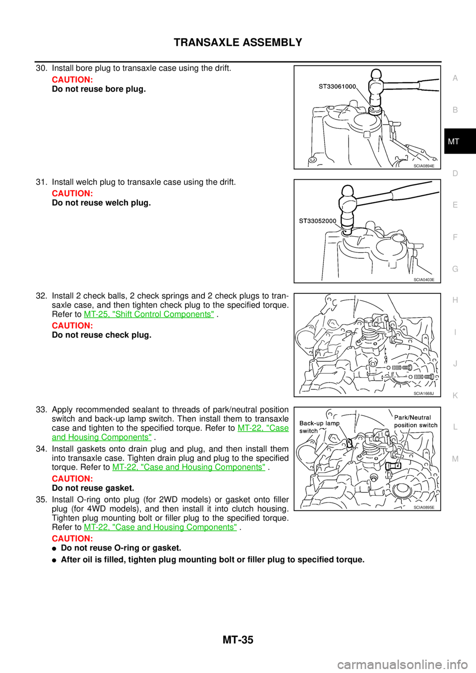
30. Install bore plug to transaxle case using the drift.
CAUTION:
Do not reuse bore plug.
31. Install welch plug to transaxle case using the drift.
CAUTION:
Do not reuse welch plug.
32. Install 2 check balls, 2 check springs and 2 check plugs to tran-
saxle case, and then tighten check plug to the specified torque.
Refer to MT-25, "
Shift Control Components" .
CAUTION:
Do not reuse check plug.
33. Apply recommended sealant to threads of park/neutral position
switch and back-up lamp switch. Then install them to transaxle
case and tighten to the specified torque. Refer to MT-22, "
Case
and Housing Components" .
34. Install gaskets onto drain plug and plug, and then install them
into transaxle case. Tighten drain plug and plug to the specified
torque. Refer to MT-22, "
Case and Housing Components" .
CAUTION:
Do not reuse gasket.
35. Install O-ring onto plug (for 2WD models) or gasket onto filler
plug (for 4WD models), and then install it into clutch housing.
Tighten plug mounting bolt or filler plug to the specified torque.
Refer to MT-22, "
Case and Housing Components" .
CAUTION:
�Do not reuse O-ring or gasket.
�After oil is filled, tighten plug mounting bolt or filler plug to specified torque.
SCIA0894E
SCIA0403E
SCIA1668J
SCIA0895E
Page 2200 of 4555
MT-44
TRANSAXLE ASSEMBLY
Final Drive Components
DISASSEMBLY
1. Remove plug (for 2WD models) or filler plug (for 4WD models) from clutch housing.
2. Remove drain plug and plug from transaxle case.
3. Remove park/neutral position switch and back-up lamp switch
from transaxle case.
4. Remove shift check and stopper bolt from transaxle case, and
then remove control assembly from transaxle case.
1. Differential side bearing outer race
(clutch housing side)2. Differential side bearing (clutch
housing side)3. Speedometer drive gear (for 2WD
models)
4. Differential case 5. Final gear 6. Differential side bearing (transaxle
case side)
7. Differential side bearing outer race
(transaxle case side)8. Differential side bearing adjusting
shim9. Pinion mate shaft
10. Side gear 11. Side gear thrust washer 12. Pinion mate gear
13. Pinion mate thrust washer 14. Retaining pin
PCIB0869E
SCIA0389E
Page 2210 of 4555

MT-54
TRANSAXLE ASSEMBLY
37. Apply recommended sealant to threads of park/neutral position
switch and back-up lamp switch. Then install them to transaxle
case and tighten to the specified torque. Refer to MT-40, "
Case
and Housing Components" .
38. Install gaskets onto drain plug and plug, and then install them
into transaxle case. Tighten drain plug and plug to the specified
torque. Refer to MT-40, "
Case and Housing Components" .
CAUTION:
Do not reuse gasket.
39. Install O-ring onto plug (for 2WD models) or gasket onto filler
plug (for 4WD models), and then install it into clutch housing.
Tighten plug mounting bolt or filler plug to the specified torque.
Refer to MT-40, "
Case and Housing Components" .
CAUTION:
�Do not reuse O-ring or gasket.
�After oil is filled, tighten plug mounting bolt or filler plug to specified torque.
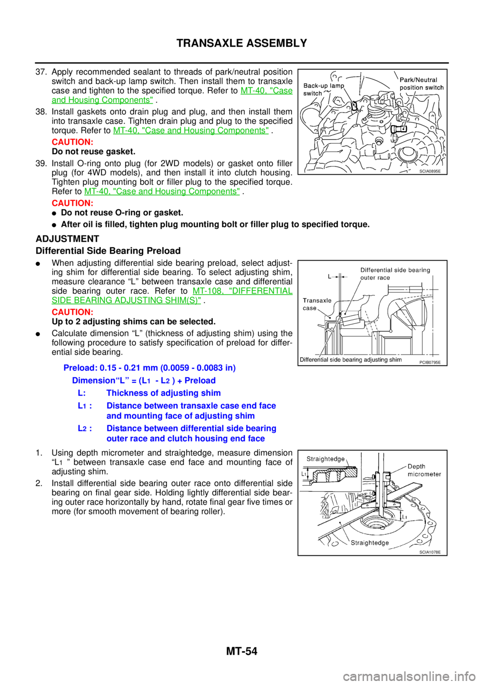
ADJUSTMENT
Differential Side Bearing Preload
�When adjusting differential side bearing preload, select adjust-
ing shim for differential side bearing. To select adjusting shim,
measure clearance “L” between transaxle case and differential
side bearing outer race. Refer to MT-108, "
DIFFERENTIAL
SIDE BEARING ADJUSTING SHIM(S)" .
CAUTION:
Up to 2 adjusting shims can be selected.
�Calculate dimension “L” (thickness of adjusting shim) using the
following procedure to satisfy specification of preload for differ-
ential side bearing.
1. Using depth micrometer and straightedge, measure dimension
“L
1 ” between transaxle case end face and mounting face of
adjusting shim.
2. Install differential side bearing outer race onto differential side
bearing on final gear side. Holding lightly differential side bear-
ing outer race horizontally by hand, rotate final gear five times or
more (for smooth movement of bearing roller).
SCIA0895E
Preload: 0.15 - 0.21 mm (0.0059 - 0.0083 in)
Dimension“L” = (L
1 - L2 ) + Preload
L: Thickness of adjusting shim
L
1 : Distance between transaxle case end face
and mounting face of adjusting shim
L
2 : Distance between differential side bearing
outer race and clutch housing end face
PCIB0795E
SCIA1078E
Page 2668 of 4555
AT-404
[ALL]
ON-VEHICLE SERVICE
ON-VEHICLE SERVICEPFP:00000
Control Valve Assembly and AccumulatorsECS0040C
COMPONENTS
1. Transaxle 2. Lip seal 3. O-ring
4. Servo release accumulator piston 5. O-ring 6. Return spring
7. Control valve assembly 8. Oil pan gasket 9. Drain plug gasket
10. Drain plug 11. Magnet 12. Oil pan
13. Oil pan fitting bolt 14. Snap ring 15. O-ring
16. O-ring 17. N-D accumulator piston 18. O-ring
19. Return spring
SCIA4320E
Page 2685 of 4555
![NISSAN X-TRAIL 2005 Service Repair Manual OVERHAUL
AT-421
[ALL]
D
E
F
G
H
I
J
K
L
MA
B
AT
10. Bracket 11. Anchor end pin 12. Lock nut
13. Transaxle case 14. Brake band 15. Bearing retainer
16. Seal ring 17. Radial needle bearing 18. Snap ri NISSAN X-TRAIL 2005 Service Repair Manual OVERHAUL
AT-421
[ALL]
D
E
F
G
H
I
J
K
L
MA
B
AT
10. Bracket 11. Anchor end pin 12. Lock nut
13. Transaxle case 14. Brake band 15. Bearing retainer
16. Seal ring 17. Radial needle bearing 18. Snap ri](/manual-img/5/57403/w960_57403-2684.png)
OVERHAUL
AT-421
[ALL]
D
E
F
G
H
I
J
K
L
MA
B
AT
10. Bracket 11. Anchor end pin 12. Lock nut
13. Transaxle case 14. Brake band 15. Bearing retainer
16. Seal ring 17. Radial needle bearing 18. Snap ring
19. Reduction pinion gear 20. Reduction pinion gear bearing inner
race21. Reduction pinion gear bearing outer
race
22. Strut 23. O-ring 24. O-ring
25. Servo release accumulator piston 26. O-ring 27. Return spring
28. Control valve assembly 29. Oil pan gasket 30. Drain plug gasket
31. Drain plug 32. Magnet 33. Oil pan
34. Oil pan fitting bolt 35. Low & reverse brake tube 36. Oil sleeve
37. O-ring 38. Snap ring 39. O-ring
40. N-D accumulator piston 41. Return spring 42. Lip seal
43. Parking rod 44. Retaining pin 45. Manual shaft oil seal
46. Detent spring 47. Manual shaft 48. Retaining pin
49. Manual plate 50. Parking rod plate 51. O/D servo piston
52. O/D servo piston retainer 53. O/D servo piston retainer fitting bolt 54. O-ring
55. D-ring 56. Servo piston retainer 57. O-ring
58. E-ring 59. Spring retainer 60. O/D servo return spring
61. D-ring 62. Band servo piston 63. Band servo thrust washer
64. Band servo piston stem 65. 2nd servo return spring 66. Parking pawl
67. Parking shaft 68. Return spring 69. Paring pawl spacer
70. PNP switch 71. Idler gear bearing 72. Idler gear
73. Idler gear lock nut 74. Reduction pinion gear adjusting
shim75. Output shaft adjusting shim
76. Side cover
Page 2877 of 4555

TRANSFER ASSEMBLY
TF-73
C
E
F
G
H
I
J
K
L
MA
B
TF
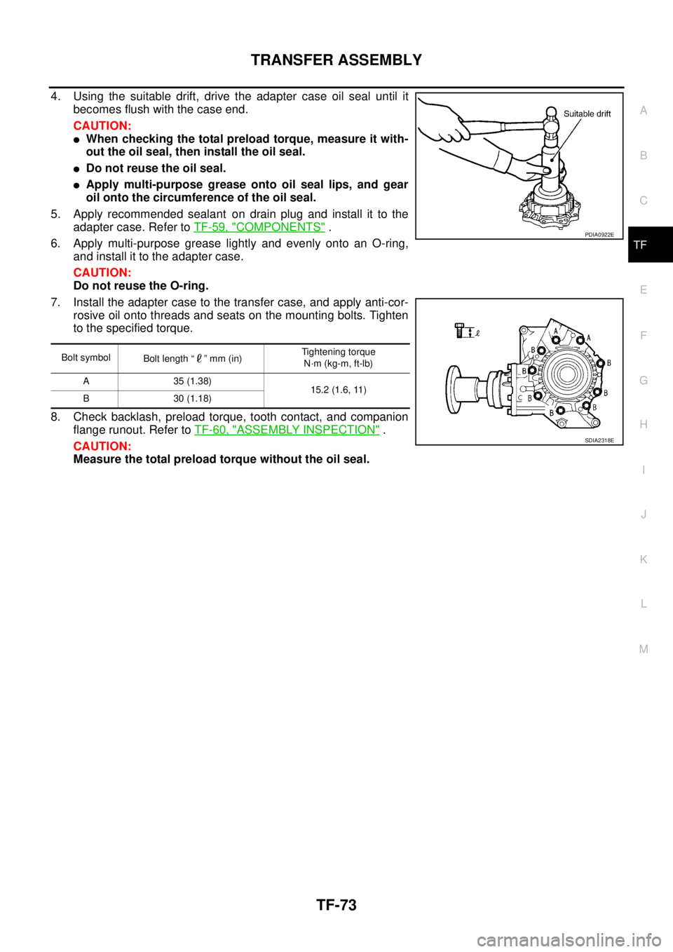
4. Using the suitable drift, drive the adapter case oil seal until it
becomes flush with the case end.
CAUTION:
�When checking the total preload torque, measure it with-
out the oil seal, then install the oil seal.
�Do not reuse the oil seal.
�Apply multi-purpose grease onto oil seal lips, and gear
oil onto the circumference of the oil seal.
5. Apply recommended sealant on drain plug and install it to the
adapter case. Refer to TF-59, "
COMPONENTS" .
6. Apply multi-purpose grease lightly and evenly onto an O-ring,
and install it to the adapter case.
CAUTION:
Do not reuse the O-ring.
7. Install the adapter case to the transfer case, and apply anti-cor-
rosive oil onto threads and seats on the mounting bolts. Tighten
to the specified torque.
8. Check backlash, preload torque, tooth contact, and companion
flange runout. Refer to TF-60, "
ASSEMBLY INSPECTION" .
CAUTION:
Measure the total preload torque without the oil seal.
Bolt symbol
Bolt length “ ” mm (in)Tightening torque
N·m (kg-m, ft-lb)
A 35 (1.38)
15.2 (1.6, 11)
B 30 (1.18)
PDIA0922E
SDIA2318E
Page 2906 of 4555
RFD-16
REAR FINAL DRIVE ASSEMBLY
ComponentsEDS001ZB
PDIA0932E
1. Companion flange lock nut 2. Companion flange 3. Front oil seal
4. Coupling cover 5. Connector bracket 6. Reamer bolt
7. Coupling front bearing 8. Bearing shim 9. Electric controlled coupling
10. 4WD solenoid harness 11. Center oil seal 12. Drive pinion nut
13. Pinion front bearing 14. Carrier case 15. Collapsible spacer
16. Drive pinion adjusting shim 17. Pinion rear bearing 18. Drive pinion
19. Side oil seal 20. Side bearing adjusting shim 21. Side bearing
22. Drive gear 23. Differential case 24. Side gear thrust washer
25. Side gear 26. Pinion mate thrust washer 27. Pinion mate gear
28. Pinion mate shaft 29. Lock pin 30. Rear cover
31. Filler plug 32. Drain plug 33. Gasket
Page 2908 of 4555

RFD-18
REAR FINAL DRIVE ASSEMBLY
DRIVE GEAR TO DRIVE PINION BACKLASH
1. Drain the oil.
2. Remove the rear cover. Refer to RFD-22, "
Removal of Differential Assembly" .
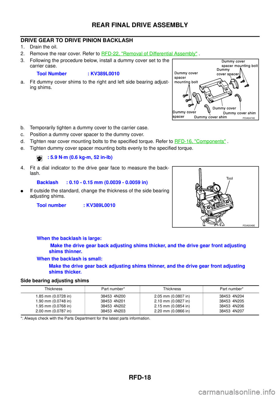
3. Following the procedure below, install a dummy cover set to the
carrier case.
a. Fit dummy cover shims to the right and left side bearing adjust-
ing shims.
b. Temporarily tighten a dummy cover to the carrier case.
c. Position a dummy cover spacer to the dummy cover.
d. Tighten rear cover mounting bolts to the specified torque. Refer to RFD-16, "
Components" .
e. Tighten dummy cover spacer mounting bolts evenly to the specified torque.
4. Fit a dial indicator to the drive gear face to measure the back-
lash.
�If outside the standard, change the thickness of the side bearing
adjusting shims.
Side bearing adjusting shims
*: Always check with the Parts Department for the latest parts information.
Tool Number : KV389L0010
PDIA0474E
: 5.9 N·m (0.6 kg-m, 52 in-lb)
Backlash : 0.10 - 0.15 mm (0.0039 - 0.0059 in)
Tool number : KV389L0010
PDIA0049E
When the backlash is large:
Make the drive gear back adjusting shims thicker, and the drive gear front adjusting
shims thinner.
When the backlash is small:
Make the drive gear back adjusting shims thinner, and the drive gear front adjusting
shims thicker.
Thickness Part number* Thickness Part number*
1.85 mm (0.0728 in)
1.90 mm (0.0748 in)
1.95 mm (0.0768 in)
2.00 mm (0.0787 in)38453 4N200
38453 4N201
38453 4N202
38453 4N2032.05 mm (0.0807 in)
2.10 mm (0.0827 in)
2.15 mm (0.0854 in)
2.20 mm (0.0866 in)38453 4N204
38453 4N205
38453 4N206
38453 4N207