Page 355 of 4555
![NISSAN X-TRAIL 2005 Service Repair Manual SERVICE DATA AND SPECIFICATIONS (SDS)
LU-33
[YD22DDTi]
C
D
E
F
G
H
I
J
K
L
MA
LU
SERVICE DATA AND SPECIFICATIONS (SDS)PFP:00030
Standard and LimitEBS00CTZ
OIL PRESSURE
OIL PUMP
Unit: mm (in)
REGULAT NISSAN X-TRAIL 2005 Service Repair Manual SERVICE DATA AND SPECIFICATIONS (SDS)
LU-33
[YD22DDTi]
C
D
E
F
G
H
I
J
K
L
MA
LU
SERVICE DATA AND SPECIFICATIONS (SDS)PFP:00030
Standard and LimitEBS00CTZ
OIL PRESSURE
OIL PUMP
Unit: mm (in)
REGULAT](/manual-img/5/57403/w960_57403-354.png)
SERVICE DATA AND SPECIFICATIONS (SDS)
LU-33
[YD22DDTi]
C
D
E
F
G
H
I
J
K
L
MA
LU
SERVICE DATA AND SPECIFICATIONS (SDS)PFP:00030
Standard and LimitEBS00CTZ
OIL PRESSURE
OIL PUMP
Unit: mm (in)
REGULATOR VALVE
Unit: mm (in)
OIL CAPACITY (APPROXIMATE)
Unit: · (Imp qt)
Tightening TorqueEBS00B0F
Unit: N·m (kg-m, ft-lb)
Unit: N·m (kg-m, in-lb)* Engine speed rpm
Approximate discharge pressure kPa (bar, kg/cm
2 , psi)
Idle speed
2,000140 (1.40, 1.43, 20.3) or more
270 (2.70, 2.75, 39.2) or more
Oil pump housing to outer rotor radial clearance 0.114 - 0.260 (0.0045 - 0.0102)
Inner rotor to outer rotor tip clearance Below 0.18 (0.0071)
Oil pump housing to inner rotor side clearance 0.050 - 0.090 (0.0020 - 0.0035)
Oil pump housing to outer rotor side clearance 0.030 - 0.190 (0.0012 - 0.0075)
Inner rotor to oil pump housing clearance 0.045 - 0.091 (0.0018 - 0.0036)
Regulator valve to valve hole clearance 0.040 - 0.097 (0.0016 - 0.0038)
With oil filter change 5.2 (4-5/8 Imp qt)
Without oil filter change 4.9 (4-3/8 Imp qt)
Dry engine (engine overhaul) 6.3 (5-1/2 Imp qt)
Oil pressure switch15 (1.5, 11)
Oil pan drain plug34 (3.5, 25)
Oil filter bracket21.5 (2.2, 16)
Oil filter (TYPE A)18 (1.8, 13)
Oil filler body (TYPE B) 22 (2.2, 16)
Oil pump cover Bolts 6.9 (0.7, 61)*
Screws 6.9 (0.7, 61)*
Regulator plug54 (5.5, 40)
Water hose connector 23.6 (2.4, 17)
Oil cooler24.5 (2.5, 18)
Page 377 of 4555
![NISSAN X-TRAIL 2005 Service Repair Manual WATER PUMP
CO-21
[QR]
C
D
E
F
G
H
I
J
K
L
MA
CO
WAT E R P U MPPFP:21020
Removal and InstallationEBS00KON
REMOVAL
1. Drain engine coolant. Refer to CO-9, "Changing Engine Coolant" .
CAUTION:
�Perfor NISSAN X-TRAIL 2005 Service Repair Manual WATER PUMP
CO-21
[QR]
C
D
E
F
G
H
I
J
K
L
MA
CO
WAT E R P U MPPFP:21020
Removal and InstallationEBS00KON
REMOVAL
1. Drain engine coolant. Refer to CO-9, "Changing Engine Coolant" .
CAUTION:
�Perfor](/manual-img/5/57403/w960_57403-376.png)
WATER PUMP
CO-21
[QR]
C
D
E
F
G
H
I
J
K
L
MA
CO
WAT E R P U MPPFP:21020
Removal and InstallationEBS00KON
REMOVAL
1. Drain engine coolant. Refer to CO-9, "Changing Engine Coolant" .
CAUTION:
�Perform this step when engine is cold.
�Do not spill engine coolant on drive belt.
2. Remove the following parts.
�RH undercover
�Drive belt; Refer to EM-13, "DRIVE BELTS" .
�Drive belt auto-tensioner; Refer to EM-14, "Removal and Installation of Drive Belt Auto-Tensioner" .
3. Remove water pump.
�Engine coolant will leak from cylinder block, so have a receptacle ready below.
CAUTION:
�Handle water pump vane so that it does not contact any other parts.
�Water pump cannot be disassembled and should be replaced as a unit.
4. Remove water pump housing with the following procedure;
a. Remove alternator. Refer to SC-13, "
CHARGING SYSTEM" .
b. Remove oil level gauge and oil level gauge guide. Refer to EM-27, "
OIL PAN AND OIL STRAINER" .
CAUTION:
Plug the oil level gauge guide opening to prevent oil pan from entering foreign materials.
c. Remove mounting bolts for water pipe.
d. Remove water pump housing.
5. Remove exhaust manifold and three way catalyst assembly. Refer to EM-25, "
EXHAUST MANIFOLD
AND THREE WAY CATALYST" .
6. Remove water pipe.
1. Water pump 2. Gasket 3. Gasket
4. Water pump housing 5. Gasket 6. Water pipe
7. O-ring
PBIC2253E
Page 399 of 4555
![NISSAN X-TRAIL 2005 Service Repair Manual WATER PUMP
CO-43
[YD22DDTi]
C
D
E
F
G
H
I
J
K
L
MA
CO
WAT E R P U MPPFP:21020
Removal and InstallationEBS00BB4
WARNING:
Do not remove radiator cap when the engine is hot. Serious burns could occur NISSAN X-TRAIL 2005 Service Repair Manual WATER PUMP
CO-43
[YD22DDTi]
C
D
E
F
G
H
I
J
K
L
MA
CO
WAT E R P U MPPFP:21020
Removal and InstallationEBS00BB4
WARNING:
Do not remove radiator cap when the engine is hot. Serious burns could occur](/manual-img/5/57403/w960_57403-398.png)
WATER PUMP
CO-43
[YD22DDTi]
C
D
E
F
G
H
I
J
K
L
MA
CO
WAT E R P U MPPFP:21020
Removal and InstallationEBS00BB4
WARNING:
Do not remove radiator cap when the engine is hot. Serious burns could occur from high pressure
engine coolant escaping from the radiator.
REMOVAL
1. Remove RH engine undercover.
2. Remove drive belt. Refer to EM-140, "
DRIVE BELTS" .
3. Drain engine coolant. Refer to CO-32, "
DRAINING ENGINE COOLANT" .
CAUTION:
Perform when engine is cold.
4. Support the bottom of oil pan (lower) with a floor jack etc, and remove RH engine mounting insulator (front
side of engine). Refer to EM-222, "
ENGINE ASSEMBLY" .
5. Remove water pump pulley.
�Loosen the pulley bolts after fixing the pulley using a screwdriver etc.
6. Remove RH engine mounting bracket.
7. Remove water pump.
�Engine coolant will leak from cylinder block, so have a receptacle ready below.
CAUTION:
�Handle the water pump vane so that it does not contact any other parts.
�Water pump cannot be disassembled and should be replaced as a unit.
1. Gasket 2. Water pump 3. RH engine mounting bracket
4. Water pump pulley
PBIC2384E
Page 2148 of 4555

CL-12
OPERATING CYLINDER
OPERATING CYLINDERPFP:30620
ComponentsECS00G84
Removal and InstallationECS008BC
REMOVAL
1. Drain clutch fluid.
CAUTION:
Keep painted surface on the body or other parts free of clutch fluid. If it spills, wipe up immediately
and wash the affected area with water.
2. Remove clutch hose from operating cylinder.
3. Remove operating cylinder mounting bolts and remove operating cylinder from the vehicle.
INSTALLATION
Note the following, and install in the reverse order of removal.
�Install hose with care so that it will not be bent or twisted.
�After completing the procedure, bleed the air from the clutch hydraulic system. Refer to CL-8, "Air Bleed-
ing Procedure" .
Disassembly and AssemblyECS008BD
DISASSEMBLY
�Remove dust cover and push rod. Then remove piston, piston cup, and piston spring from inside cylinder
body.
INSPECTION AFTER DISASSEMBLY
Check for any of the conditions shown below. If any malfunction is found, replace the part concerned.
�Damage to cylinder internal surface or piston sliding surface. Foreign matter, wear, corrosion, or pinhole
�Settling of piston spring
�Cracked or deformed dust cover
ASSEMBLY
1. Apply rubber lubricant to cylinder body internal surface and rubber grease to piston cup and piston. Insert
piston assembly and piston spring into cylinder body.
2. Apply rubber grease to dust cover and install push rod and dust cover.
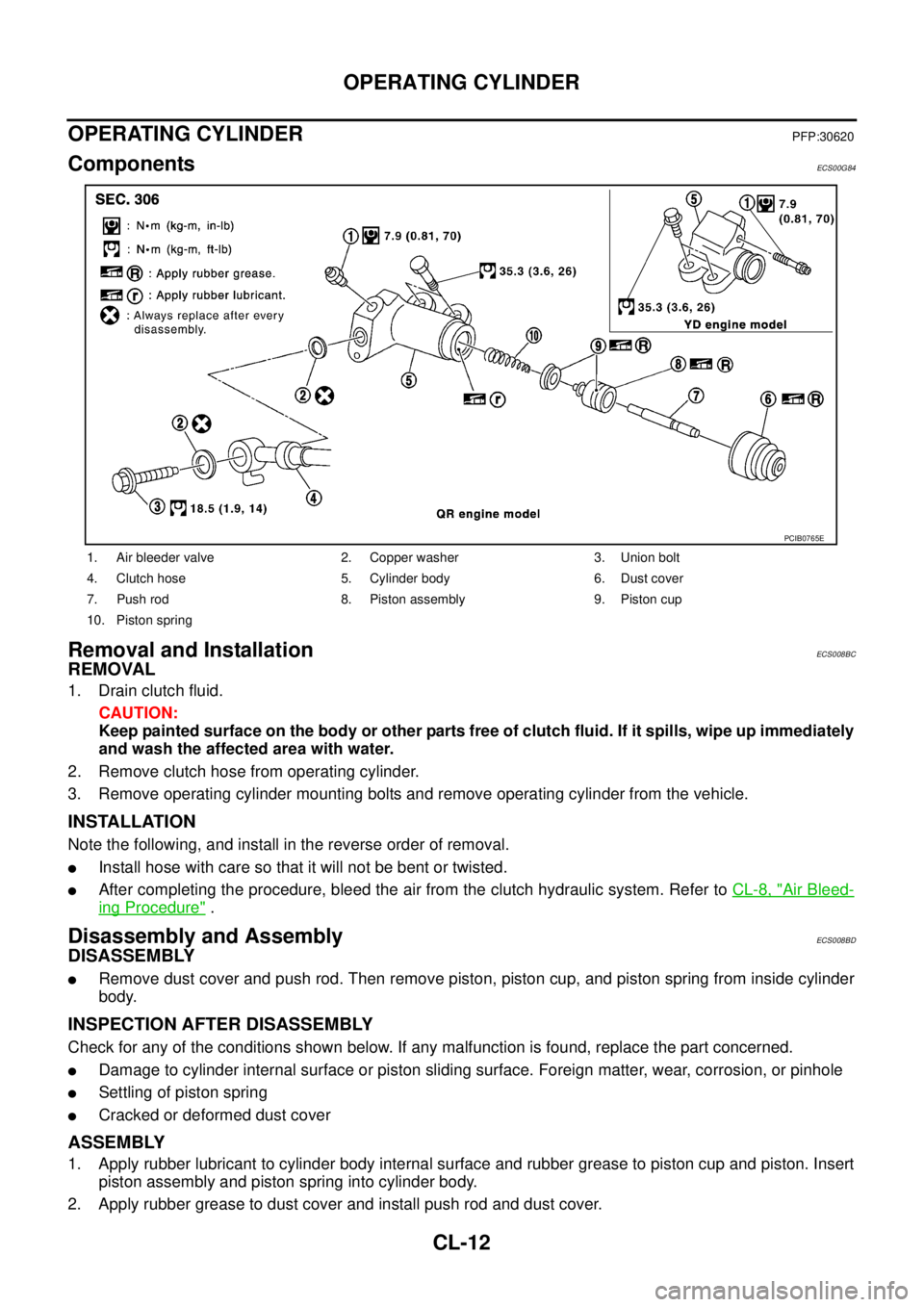
1. Air bleeder valve 2. Copper washer 3. Union bolt
4. Clutch hose 5. Cylinder body 6. Dust cover
7. Push rod 8. Piston assembly 9. Piston cup
10. Piston spring
PCIB0765E
Page 2159 of 4555
PRECAUTIONS
MT-3
D
E
F
G
H
I
J
K
L
MA
B
MT
PRECAUTIONSPFP:00001
Service Notice or PrecautionsECS008BM
�Do not reuse transaxle oil, once it has been drained.
�Check oil level or replace oil with vehicle on level surface.
�During removal or installation, keep inside of transaxle clear of dust or dirt.
�Check for the correct installation status prior to removal or disassembly. If matching mark are required, be
certain they do not interfere with the function of the parts they are applied.
�In principle, tighten bolts or nuts gradually in several steps working diagonally from inside to outside. If
tightening sequence is specified, use it.
�Be careful not to damage sliding surfaces and mating surfaces.
Page 2168 of 4555

MT-12
M/T OIL
M/T OILPFP:KLD20
Changing M/T OilECS008BR
DRAINING
1. Start engine and let it run to warm up transaxle.
2. Stop engine. Remove drain plug and then drain oil.
3. Set a gasket on drain plug and install it to transaxle case. Tighten drain plug to the specified torque. Refer
to MT-22, "
Case and Housing Components" (RS5F51A) or MT-40, "Case and Housing Components"
(RS6F51A).
CAUTION:
Do not reuse gasket.
FILLING
1. Remove plug (for 2WD models) or filler plug (for 4WD models).
Fill with new oil to transaxle.
2. After refilling oil, check oil level.
3. Set a O-ring on plug (for 2WD models) or gasket on filler plug
(for 4WD models) and then install it to clutch housing.
CAUTION:
Do not reuse O-ring or gasket.
4. Tighten plug mounting bolt (for 2WD models) or filler plug (for 4WD models) to the specified torque. Refer
to MT-22, "
Case and Housing Components" (RS5F51A) or MT-40, "Case and Housing Components"
(RS6F51A).
Checking M/T OilECS008BS
OIL LEAKAGE AND OIL LEVEL
�Make sure that oil is not leaking from transaxle or around it.
�Remove plug (for 2WD models) or filler plug (for 4WD models).
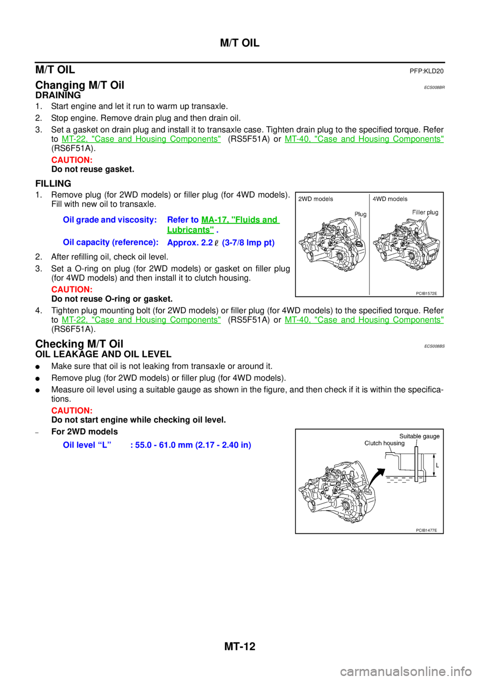
�Measure oil level using a suitable gauge as shown in the figure, and then check if it is within the specifica-
tions.
CAUTION:
Do not start engine while checking oil level.
–For 2WD modelsOil grade and viscosity: Refer to MA-17, "
Fluids and
Lubricants" .
Oil capacity (reference):
Approx. 2.2 (3-7/8 lmp pt)
PCIB1572E
Oil level “L” : 55.0 - 61.0 mm (2.17 - 2.40 in)
PCIB1477E
Page 2176 of 4555

MT-20
TRANSAXLE ASSEMBLY
4WD models
REMOVAL
1. Disconnect the battery cable from the negative terminal.
2. Remove air cleaner, air duct and battery. Refer to EM-16, "
Removal and Installation" (QR engine models)
or EM-142, "
Removal and Installation" (YD engine models).
3. Remove air breather hose. Refer to MT-18, "
Removal and Installation" .
4. Remove clutch operating cylinder. Refer to CL-12, "
Removal and Installation" .
CAUTION:
Do not depress clutch pedal during removal procedure.
5. Disconnect control cable from transaxle assembly. Refer to MT-17, "
Removal and Installation" .
6. Drain gear oil. Refer to MT-12, "
DRAINING" .
7. Disconnect PNP switch, back-up lamp switch and ground harness connectors.
8. Remove exhaust front tube. Refer to EX-2, "
Removal and Installation" .
9. Remove drive shaft. Refer to FAX-11, "
FRONT DRIVE SHAFT" .
10. Remove transfer (for 4WD models). Refer to TF-57, "
Removal and Installation" .
11. Remove starter motor. Refer to SC-27, "
Removal and Installation" .
12. Support transaxle assembly with a jack.
CAUTION:
When setting a jack, be careful not to bring it into contact with switches.
13. Remove center member, engine insulator and engine mount bracket. Refer to EM-81, "
ENGINE ASSEM-
BLY" (QR engine models) or EM-222, "ENGINE ASSEMBLY" (YD engine models).
14. Remove suspension members (for 4WD models). Refer to FSU-12, "
FRONT SUSPENSION MEMBER" .
15. Support engine with a jack under oil pan.
16. Remove transaxle assembly mounting bolts.
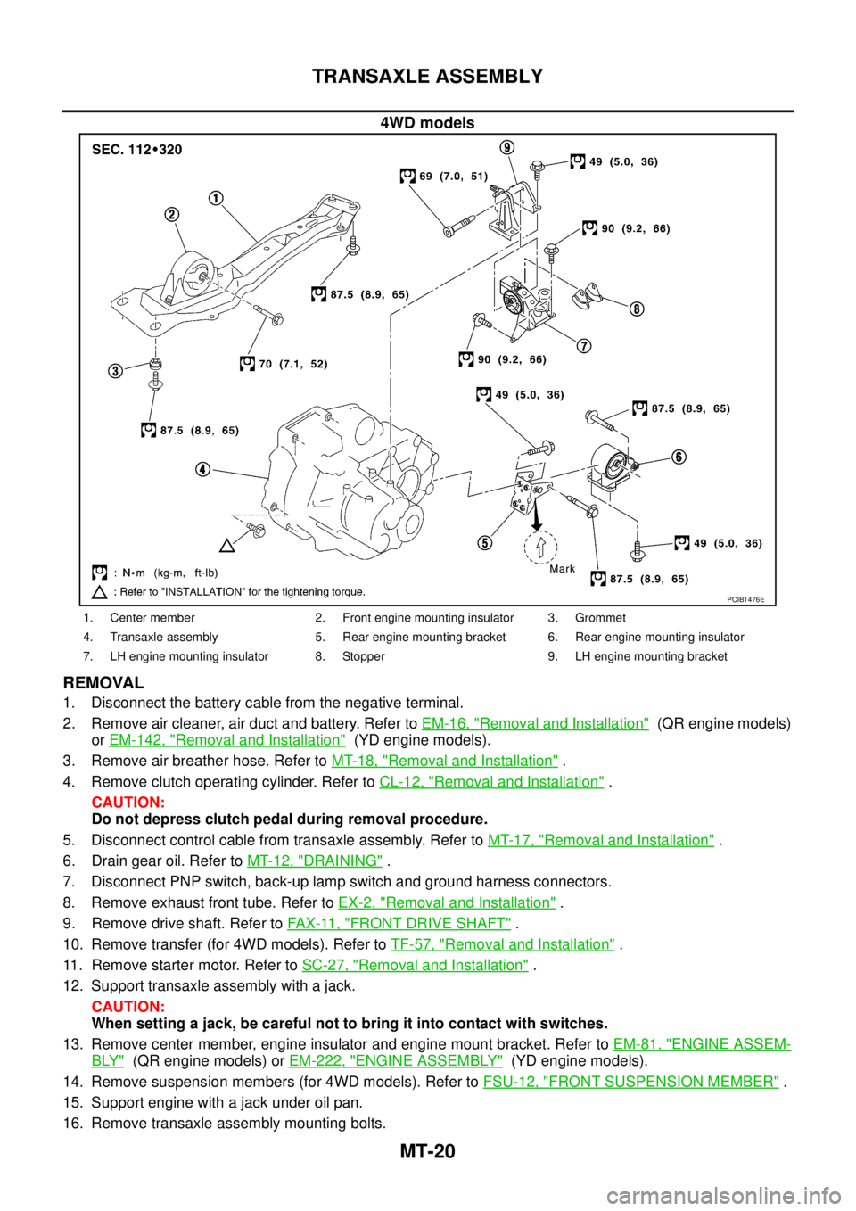
PCIB1476E
1. Center member 2. Front engine mounting insulator 3. Grommet
4. Transaxle assembly 5. Rear engine mounting bracket 6. Rear engine mounting insulator
7. LH engine mounting insulator 8. Stopper 9. LH engine mounting bracket
Page 2182 of 4555
MT-26
TRANSAXLE ASSEMBLY
Final Drive Components
DISASSEMBLY
1. Remove plug (for 2WD models) or filler plug (for 4WD models) from clutch housing.
2. Remove drain plug and plug from transaxle case.
3. Remove park/neutral position switch and back-up lamp switch
from transaxle case.
4. Remove shift check and stopper bolt from transaxle case, and
then remove control assembly from transaxle case.
1. Differential side bearing outer race
(clutch housing side)2. Differential side bearing (clutch
housing side)3. Speedometer drive gear (for 2WD
models)
4. Differential case 5. Final gear 6. Differential side bearing (transaxle
case side)
7. Differential side bearing outer race
(transaxle case side)8. Differential side bearing adjusting
shim9. Pinion mate shaft
10. Side gear 11. Side gear thrust washer 12. Pinion mate gear
13. Pinion mate thrust washer 14. Retaining pin
PCIB0869E
SCIA0389E