Page 145 of 4555
![NISSAN X-TRAIL 2005 Service Repair Manual CYLINDER BLOCK
EM-91
[QR]
C
D
E
F
G
H
I
J
K
L
MA
EM
�A widely use engine stand can be used.
NOTE:
This example is an engine stand for holding at transaxle
mounting side with flywheel (M/T models) or](/manual-img/5/57403/w960_57403-144.png "NISSAN X-TRAIL 2005 Service Repair Manual CYLINDER BLOCK
EM-91
[QR]
C
D
E
F
G
H
I
J
K
L
MA
EM
�A widely use engine stand can be used.
NOTE:
This example is an engine stand for holding at transaxle
mounting side with flywheel (M/T models) or")
CYLINDER BLOCK
EM-91
[QR]
C
D
E
F
G
H
I
J
K
L
MA
EM
�A widely use engine stand can be used.
NOTE:
This example is an engine stand for holding at transaxle
mounting side with flywheel (M/T models) or drive plate (A/T
models) removed.
3. Drain engine oil. Refer to LU-8, "
Changing Engine Oil" .
4. Drain engine coolant by removing water drain plug from inside of
engine.
5. Remove cylinder head. Refer to EM-70, "
CYLINDER HEAD" .
6. Remove knock sensor.
CAUTION:
Carefully handle knock sensor avoiding shocks.
7. Remove crankshaft position sensor (POS).
CAUTION:
�Avoid impacts such as a dropping.
�Do not disassemble.
�Keep it away from metal particles.
�Do not place sensor in a location where it is exposed to
magnetism.
8. Remove clutch cover and clutch disc (M/T models). Refer to CL-16, "
CLUTCH DISC, CLUTCH COVER
AND FLYWHEEL" .
9. Remove flywheel (M/T models) or drive plate (A/T models).
�Secure crankshaft with a stopper plate, and remove mounting
bolts.
�Using the following TORX socket, loosen mounting bolts.
CAUTION:
Be careful not to damage contact surface for clutch disc of
flywheel (M/T models).
PBIC0085E
PBIC2716E
PBIC2191E
Flywheel (M/T models)
: size T55 (commercial service tool)
Drive plate (A/T models)
: size E20
PBIC2352E
Page 181 of 4555
![NISSAN X-TRAIL 2005 Service Repair Manual SERVICE DATA AND SPECIFICATIONS (SDS)
EM-127
[QR]
C
D
E
F
G
H
I
J
K
L
MA
EM
CONNECTING ROD BEARING
Undersize
Unit: mm (in)
Bearing Oil Clearance
Unit: mm (in)
Tightening TorqueEBS00KNY
Unit: N·m (k](/manual-img/5/57403/w960_57403-180.png "NISSAN X-TRAIL 2005 Service Repair Manual SERVICE DATA AND SPECIFICATIONS (SDS)
EM-127
[QR]
C
D
E
F
G
H
I
J
K
L
MA
EM
CONNECTING ROD BEARING
Undersize
Unit: mm (in)
Bearing Oil Clearance
Unit: mm (in)
Tightening TorqueEBS00KNY
Unit: N·m (k")
SERVICE DATA AND SPECIFICATIONS (SDS)
EM-127
[QR]
C
D
E
F
G
H
I
J
K
L
MA
EM
CONNECTING ROD BEARING
Undersize
Unit: mm (in)
Bearing Oil Clearance
Unit: mm (in)
Tightening TorqueEBS00KNY
Unit: N·m (kg-m, ft-lb)
Unit: N·m (kg-m, in-lb)*2
Grade number Thickness mm (in) Identification color
0 1.495 - 1.499 (0.0589 - 0.0590) Black
1 1.499 - 1.503 (0.0590 - 0.0592) Brown
2 1.503 - 1.507 (0.0592 - 0.0593) Green
3 1.507 - 1.511(0.0593 - 0.0595) Yellow
Item Thickness Crank pin journal diameter
US 0.25 (0.0098) 1.624 - 1.632 (0.0639 - 0.0643) Grind so that bearing clearance is the specified value.
Connecting rod bearing oil clearanceStandard 0.028 - 0.045 (0.0011 - 0.0018)
Limit 0.10 (0.0039)
*1: Parts to be tightened in particular orders.
1)-: Order of tightening when tightening two or more times separately.
Drive belt auto-tensioner 21.6 (2.2, 16)
Mass air flow sensor
3.8 (0.39, 34) *
2
Resonator
3.8 (0.39, 34)*2
Air cleaner case lower
3.8 (0.39, 34)*2
*1 Intake manifold19.6 (2.0, 14)
Intake manifold collector (QR25DE) 19.6 (2.0, 14)
Intake manifold support (QR20DE) 19.6 (2.0, 14)
Intake manifold support (QR25DE) M6 bolt
8.83 (0.90, 78) *
2
M10 bolt 46.6 (4.8, 34)
Intake manifold rear support (QR25DE) 19.6 (2.0, 14)
Electric throttle control actuator
8.43 (0.86, 75) *
2
EVAP canister purge volume control solenoid valve
5.1 (0.52, 45) *2
*1 Exhaust manifold and three way catalyst assembly 41.7 (4.3, 31)
Exhaust manifold covers (upper and lower)
5.8 (0.59, 51) *
2
Three way catalyst cover
5.8 (0.59, 51) *2
Heated oxygen sensor 1 45 (4.6, 33)
Heated oxygen sensor 2 45 (4.6, 33)
*1 Oil pan upper M6 bolt
8.8 (0.90, 78) *
2
M8 bolt 21.6 (2.2, 16)
Oil pan upper to transaxle joint bolts 42.7 (4.4, 31)
*1 Oil pan lower
6.9 (0.70, 61) *
2
Oil pan drain plug34.3 (3.5, 25)
Rear plate cover
6.9 (0.70, 61) *
2
Oil level gauge guide 21.6 (2.2, 16)
Page 182 of 4555
![NISSAN X-TRAIL 2005 Service Repair Manual EM-128
[QR]
SERVICE DATA AND SPECIFICATIONS (SDS)
Oil strainer M6 bolt
8.8 (0.90, 78) *2
M8 bolt 21.6 (2.2, 16)
Ignition coil
6.4 (0.65, 57) *
2
Spark plug24.5 (2.5, 18)
*1 Fuel tube1) 10.1 (1.0, 7)](/manual-img/5/57403/w960_57403-181.png "NISSAN X-TRAIL 2005 Service Repair Manual EM-128
[QR]
SERVICE DATA AND SPECIFICATIONS (SDS)
Oil strainer M6 bolt
8.8 (0.90, 78) *2
M8 bolt 21.6 (2.2, 16)
Ignition coil
6.4 (0.65, 57) *
2
Spark plug24.5 (2.5, 18)
*1 Fuel tube1) 10.1 (1.0, 7)")
EM-128
[QR]
SERVICE DATA AND SPECIFICATIONS (SDS)
Oil strainer M6 bolt
8.8 (0.90, 78) *2
M8 bolt 21.6 (2.2, 16)
Ignition coil
6.4 (0.65, 57) *
2
Spark plug24.5 (2.5, 18)
*1 Fuel tube1) 10.1 (1.0, 7)
2) 23.6 (2.4, 17)
*1 Rocker cover 1)
2.0 (0.20, 18) *
2
2)
8.3 (0.85, 73) *2
PCV valve
2.5 (0.26, 22) *2
Intake valve timing control solenoid valve
6.4 (0.65, 57) *2
*1 Intake valve timing control cover 12.8 (1.3, 9)
Camshaft position sensor (PHASE)
6.4 (0.65, 57) *
2
Camshaft sprockets (Intake and Exhaust) 142 (14, 105)
Chain tensioner
7.0 (0.71, 62) *
2
*1 Camshaft bracket 1) 2.0 (0.2, 1)
2) 5.9 (0.6, 4)
3) 10.4 (1.1, 8)
Crankshaft pulley 1) 42.1 (4.3, 31)
2) 60° (Angle tightening)
*1 Front cover 12.8 (1.3, 9)
Timing chain slack guide 16.7 (1.7, 12)
Timing chain tension guide 16.7 (1.7, 12)
Balancer unit timing chain tensioner
7.0 (0.71, 62) *
2
*1 Balancer unit 1) 48.1 (4.9, 35)
2) 90° (Angle tightening)
3) 0 (0, 0)
4) 48.1 (4.9, 35)
5) 90° (Angle tightening)
*1 Cylinder head 1) 50 (5.1, 37)
2) 60° (Angle tightening)
3) 0 (0.0, 0)
3) 39.2 (4.0, 29)
4) 75° (Angle tightening)
5) 75° (Angle tightening)
Flywheel (M/T)108 (11, 80)
Drive plate (A/T)108 (11, 80)
Connecting rod bearing cap 1) 19.6 (2.0, 14)
2) 90° (Angle tightening)
*1 Lower cylinder block M8 bolt 1) 25.1 (2.6, 19)
M10 bolt 2) 39.2 (4.0, 29)
M10 bolt 3) 60° (Angle tightening)
Signal plate18.5 (1.9, 14)
Water drain plug
9.8 (1.0, 87) *
2
Page 184 of 4555
![NISSAN X-TRAIL 2005 Service Repair Manual EM-130
[YD22DDTi]
PRECAUTIONS
[YD22DDTi]PRECAUTIONSPFP:00001
Precautions for Draining Engine CoolantEBS00LQZ
Drain engine coolant when engine is cooled.
Precautions for Disconnecting Fuel PipingEBS0](/manual-img/5/57403/w960_57403-183.png "NISSAN X-TRAIL 2005 Service Repair Manual EM-130
[YD22DDTi]
PRECAUTIONS
[YD22DDTi]PRECAUTIONSPFP:00001
Precautions for Draining Engine CoolantEBS00LQZ
Drain engine coolant when engine is cooled.
Precautions for Disconnecting Fuel PipingEBS0")
EM-130
[YD22DDTi]
PRECAUTIONS
[YD22DDTi]PRECAUTIONSPFP:00001
Precautions for Draining Engine CoolantEBS00LQZ
Drain engine coolant when engine is cooled.
Precautions for Disconnecting Fuel PipingEBS00LR0
�Before starting work, make sure no fire or spark producing items are in the work area.
�After disconnecting pipes, plug openings to stop fuel leakage.
Precautions for Removal and DisassemblyEBS00LR1
�When instructed to use special service tools, use the specified tools. Always be careful to work safely,
avoid forceful or uninstructed operations.
�Exercise maximum care to avoid damage to mating or sliding surfaces.
�Cover openings of engine system with tape or the equivalent, if necessary, to seal out foreign materials.
�Mark and arrange disassembly parts in an organized way for easy troubleshooting and re-assembly.
�When loosening nuts and bolts, as a basic rule, start with the one furthest outside, then the one diagonally
opposite, and so on. If the order of loosening is specified, do exactly as specified.
Precautions for Inspection, Repair and ReplacementEBS00LR2
Before repairing or replacing, thoroughly inspect parts. Inspect new replacement parts in the same way, and
replace if necessary.
Precautions for Assembly and InstallationEBS00LR3
�Use torque wrench to tighten bolts or nuts to specification.
�When tightening nuts and bolts, as a basic rule, equally tighten in several different steps starting with the
ones in center, then ones on inside and outside diagonally in this order. If the order of tightening is speci-
fied, do exactly as specified.
�Replace with new liquid gasket, packing, oil seal or O-ring.
�Dowel pins are used for several parts alignment. When replacing and reassembling parts with dowel pins,
make sure that dowel pins are installed in the original position.
�Thoroughly wash, clean, and air-blow each part. Carefully check engine oil or engine coolant passages for
any restriction and blockage.
�Avoid damaging sliding or mating surfaces. Completely remove foreign materials such as cloth lint or dust.
Before assembly, engine oil sliding surfaces well.
�Release air within route when refilling after draining coolant.
�After repairing, start engine and increase engine speed to check engine coolant, fuel, engine oil, and
exhaust systems for leakage.
Parts Requiring Angle TighteningEBS00LR4
�Use an angle wrench (special service tool: KV10112100) for the final tightening of the following engine
parts:
–Cylinder head bolts
–Main bearing cap bolts
–Connecting rod cap nuts
–Crankshaft pulley bolt (No angle wrench is required as the bolt flange is provided with notches for angle
tightening)
�Do not use a torque value for final tightening.
�The torque value for these parts are for a preliminary step.
�Ensure thread and seat surfaces are clean and coated with engine oil.
Page 203 of 4555
![NISSAN X-TRAIL 2005 Service Repair Manual CATALYST
EM-149
[YD22DDTi]
C
D
E
F
G
H
I
J
K
L
MA
EM
CATALYSTPFP:20905
Removal and InstallationEBS00LRG
REMOVAL
1. Remove engine undercover.
2. Drain engine coolant. Refer to CO-32, "
Changing Engin](/manual-img/5/57403/w960_57403-202.png "NISSAN X-TRAIL 2005 Service Repair Manual CATALYST
EM-149
[YD22DDTi]
C
D
E
F
G
H
I
J
K
L
MA
EM
CATALYSTPFP:20905
Removal and InstallationEBS00LRG
REMOVAL
1. Remove engine undercover.
2. Drain engine coolant. Refer to CO-32, \"
Changing Engin")
CATALYST
EM-149
[YD22DDTi]
C
D
E
F
G
H
I
J
K
L
MA
EM
CATALYSTPFP:20905
Removal and InstallationEBS00LRG
REMOVAL
1. Remove engine undercover.
2. Drain engine coolant. Refer to CO-32, "
Changing Engine Coolant" .
3. Remove radiator hose (upper and lower). Refer to CO-35, "
RADIATOR" .
4. Remove cooling fan assembly. Refer to CO-37, "
DISASSEMBLY AND ASSEMBLY" .
5. Remove radiator mounting bracket and radiator. Refer to CO-35, "
Removal and Installation" .
6. Remove water inlet pipe. Refer to CO-45, "
THERMOSTAT AND WATER PIPING" .
7. Remove catalyst insulators.
8. Remove exhaust front tube. Refer to EX-2, "
EXHAUST SYSTEM" .
9. Remove catalyst.
CAUTION:
Do not disassemble.
NOTE:
Install two locking pins into both sides of the catalyst. Be careful not to confuse locking pins with insulator
mounting bolts.
1. Catalyst insulator 2. Gasket 3. Catalyst
4. Locking pin 5. Gusset 6. Gasket cap
7. Catalyst rear diffuser 8. Turbocharger insulator
PBIC2670E
Catalyst locking pin : Flange bolt (black)
Page 205 of 4555
![NISSAN X-TRAIL 2005 Service Repair Manual EXHAUST MANIFOLD AND TURBOCHARGER
EM-151
[YD22DDTi]
C
D
E
F
G
H
I
J
K
L
MA
EM
EXHAUST MANIFOLD AND TURBOCHARGERPFP:14004
Removal and InstallationEBS00LRH
REMOVAL
1. Drain engine coolant. Refer to CO](/manual-img/5/57403/w960_57403-204.png "NISSAN X-TRAIL 2005 Service Repair Manual EXHAUST MANIFOLD AND TURBOCHARGER
EM-151
[YD22DDTi]
C
D
E
F
G
H
I
J
K
L
MA
EM
EXHAUST MANIFOLD AND TURBOCHARGERPFP:14004
Removal and InstallationEBS00LRH
REMOVAL
1. Drain engine coolant. Refer to CO")
EXHAUST MANIFOLD AND TURBOCHARGER
EM-151
[YD22DDTi]
C
D
E
F
G
H
I
J
K
L
MA
EM
EXHAUST MANIFOLD AND TURBOCHARGERPFP:14004
Removal and InstallationEBS00LRH
REMOVAL
1. Drain engine coolant. Refer to CO-32, "Changing Engine Coolant" .
CAUTION:
�Perform this step when engine is cold.
�Do not spill engine coolant on drive belts.
2. Remove charge air cooler. Refer to EM-144, "
Removal and Installation" .
3. Remove air duct. Refer to EM-142, "
Removal and Installation" .
4. Remove air inlet pipe.
5. Remove engine undercover.
6. Remove radiator hose (upper and lower). Refer to CO-35, "
RADIATOR" .
7. Remove cooling fan assembly. Refer to CO-37, "
DISASSEMBLY AND ASSEMBLY" .
8. Remove radiator mounting bracket and radiator. Refer to CO-35, "
Removal and Installation" .
9. Remove water inlet pipe. Refer to CO-45, "
THERMOSTAT AND WATER PIPING" .
10. Remove catalyst. Refer to EM-149, "
Removal and Installation" .
11. Remove exhaust manifold insulator.
1. EGR volume control valve 2. Gasket 3. EGR cooler
4. Air inlet pipe 5.Exhaust manifold and turbocharger
assembly6. Oil feed tube
7. Oil return hose 8. Washer 9. Eye-bolt
10. Turbocharger insulator 11. Exhaust manifold insulator 12. Air inlet pipe
PBIC3614E
Page 211 of 4555
OIL PAN AND OIL STRAINER
EM-157
[YD22DDTi]
C
D
E
F
G
H
I
J
K
L
MA
EM
OIL PAN AND OIL STRAINERP F P : 1111 0
Removal and InstallationEBS00LRK
REMOVAL
WARNING:
To avoid the danger of being scalded, do not drain engine oil when engine is hot.
1. Remove engine undercover.
2. Drain engine oil. Refer to LU-21, "
Changing Engine Oil" .
3. Remove oil pan lower as follows:
a. Loosen bolts in reverse order of that shown in the figure to
remove.
1. Rear plate cover 2. Oil pan upper 3. Gasket
4. Oil strainer 5. Oil pan drain plug 6. Drain plug washer
7. Oil pan lower 8. Crankshaft position sensor
PBIC2313E
SBIA0161E
Page 215 of 4555
OIL PAN AND OIL STRAINER
EM-161
[YD22DDTi]
C
D
E
F
G
H
I
J
K
L
MA
EM
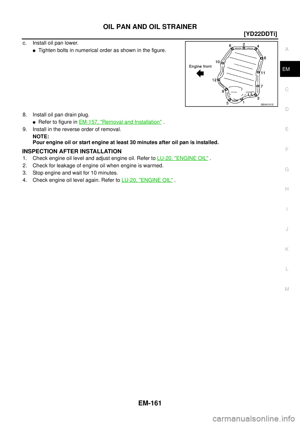
c. Install oil pan lower.
�Tighten bolts in numerical order as shown in the figure.
8. Install oil pan drain plug.
�Refer to figure in EM-157, "Removal and Installation" .
9. Install in the reverse order of removal.
NOTE:
Pour engine oil or start engine at least 30 minutes after oil pan is installed.
INSPECTION AFTER INSTALLATION
1. Check engine oil level and adjust engine oil. Refer to LU-20, "ENGINE OIL" .
2. Check for leakage of engine oil when engine is warmed.
3. Stop engine and wait for 10 minutes.
4. Check engine oil level again. Refer to LU-20, "
ENGINE OIL" .
SBIA0161E
![NISSAN X-TRAIL 2005 Service Repair Manual OIL PAN AND OIL STRAINER
EM-157
[YD22DDTi]
C
D
E
F
G
H
I
J
K
L
MA
EM
OIL PAN AND OIL STRAINERP F P : 1111 0
Removal and InstallationEBS00LRK
REMOVAL
WARNING:
To avoid the danger of being scalded, do](/manual-img/5/57403/w960_57403-210.png "NISSAN X-TRAIL 2005 Service Repair Manual OIL PAN AND OIL STRAINER
EM-157
[YD22DDTi]
C
D
E
F
G
H
I
J
K
L
MA
EM
OIL PAN AND OIL STRAINERP F P : 1111 0
Removal and InstallationEBS00LRK
REMOVAL
WARNING:
To avoid the danger of being scalded, do")