Page 184 of 4555
![NISSAN X-TRAIL 2005 Service Repair Manual EM-130
[YD22DDTi]
PRECAUTIONS
[YD22DDTi]PRECAUTIONSPFP:00001
Precautions for Draining Engine CoolantEBS00LQZ
Drain engine coolant when engine is cooled.
Precautions for Disconnecting Fuel PipingEBS0](/manual-img/5/57403/w960_57403-183.png "NISSAN X-TRAIL 2005 Service Repair Manual EM-130
[YD22DDTi]
PRECAUTIONS
[YD22DDTi]PRECAUTIONSPFP:00001
Precautions for Draining Engine CoolantEBS00LQZ
Drain engine coolant when engine is cooled.
Precautions for Disconnecting Fuel PipingEBS0")
EM-130
[YD22DDTi]
PRECAUTIONS
[YD22DDTi]PRECAUTIONSPFP:00001
Precautions for Draining Engine CoolantEBS00LQZ
Drain engine coolant when engine is cooled.
Precautions for Disconnecting Fuel PipingEBS00LR0
�Before starting work, make sure no fire or spark producing items are in the work area.
�After disconnecting pipes, plug openings to stop fuel leakage.
Precautions for Removal and DisassemblyEBS00LR1
�When instructed to use special service tools, use the specified tools. Always be careful to work safely,
avoid forceful or uninstructed operations.
�Exercise maximum care to avoid damage to mating or sliding surfaces.
�Cover openings of engine system with tape or the equivalent, if necessary, to seal out foreign materials.
�Mark and arrange disassembly parts in an organized way for easy troubleshooting and re-assembly.
�When loosening nuts and bolts, as a basic rule, start with the one furthest outside, then the one diagonally
opposite, and so on. If the order of loosening is specified, do exactly as specified.
Precautions for Inspection, Repair and ReplacementEBS00LR2
Before repairing or replacing, thoroughly inspect parts. Inspect new replacement parts in the same way, and
replace if necessary.
Precautions for Assembly and InstallationEBS00LR3
�Use torque wrench to tighten bolts or nuts to specification.
�When tightening nuts and bolts, as a basic rule, equally tighten in several different steps starting with the
ones in center, then ones on inside and outside diagonally in this order. If the order of tightening is speci-
fied, do exactly as specified.
�Replace with new liquid gasket, packing, oil seal or O-ring.
�Dowel pins are used for several parts alignment. When replacing and reassembling parts with dowel pins,
make sure that dowel pins are installed in the original position.
�Thoroughly wash, clean, and air-blow each part. Carefully check engine oil or engine coolant passages for
any restriction and blockage.
�Avoid damaging sliding or mating surfaces. Completely remove foreign materials such as cloth lint or dust.
Before assembly, engine oil sliding surfaces well.
�Release air within route when refilling after draining coolant.
�After repairing, start engine and increase engine speed to check engine coolant, fuel, engine oil, and
exhaust systems for leakage.
Parts Requiring Angle TighteningEBS00LR4
�Use an angle wrench (special service tool: KV10112100) for the final tightening of the following engine
parts:
–Cylinder head bolts
–Main bearing cap bolts
–Connecting rod cap nuts
–Crankshaft pulley bolt (No angle wrench is required as the bolt flange is provided with notches for angle
tightening)
�Do not use a torque value for final tightening.
�The torque value for these parts are for a preliminary step.
�Ensure thread and seat surfaces are clean and coated with engine oil.
Page 202 of 4555
EM-148
[YD22DDTi]
INTAKE MANIFOLD
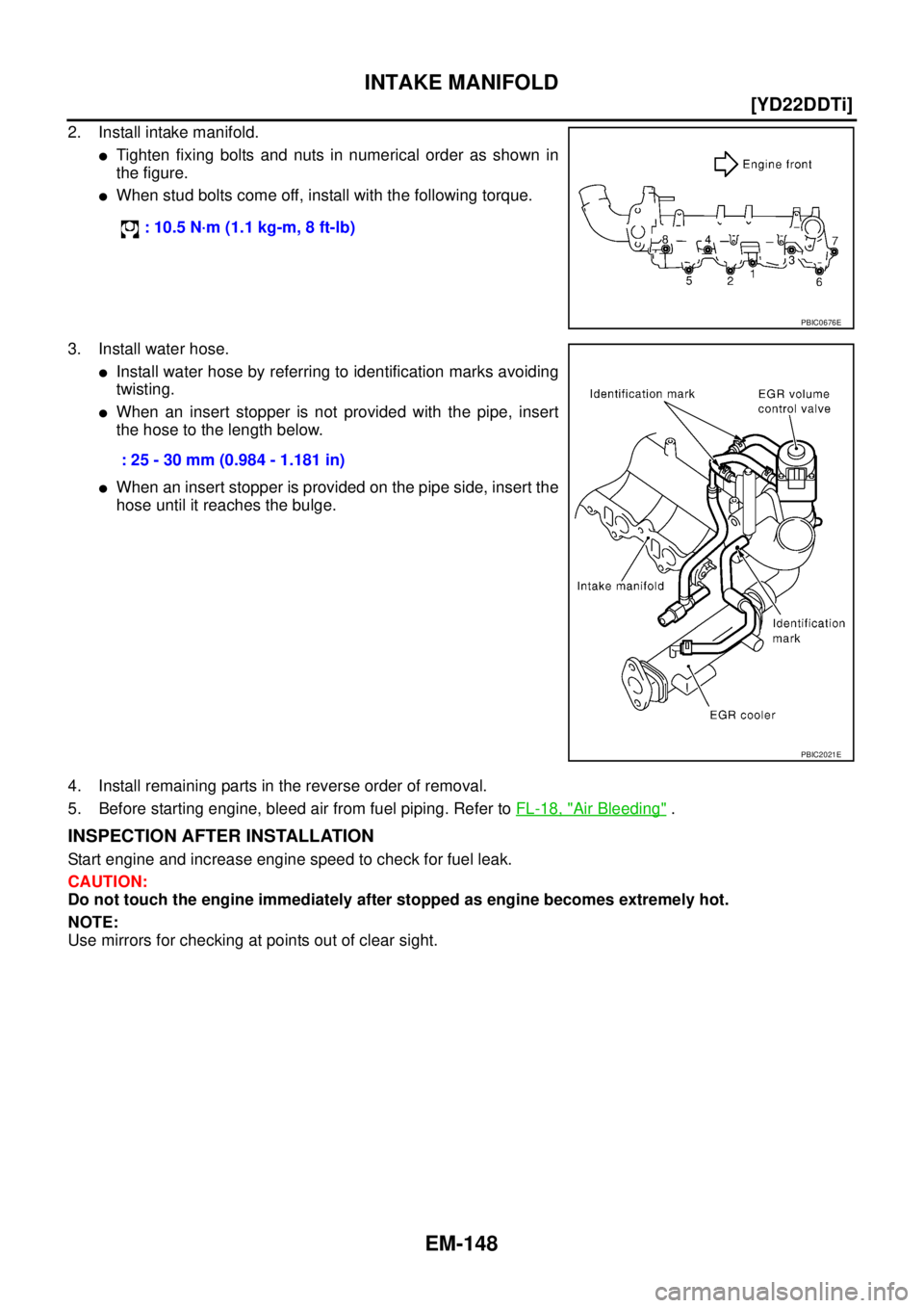
2. Install intake manifold.
�Tighten fixing bolts and nuts in numerical order as shown in
the figure.
�When stud bolts come off, install with the following torque.
3. Install water hose.
�Install water hose by referring to identification marks avoiding
twisting.
�When an insert stopper is not provided with the pipe, insert
the hose to the length below.
�When an insert stopper is provided on the pipe side, insert the
hose until it reaches the bulge.
4. Install remaining parts in the reverse order of removal.
5. Before starting engine, bleed air from fuel piping. Refer to FL-18, "
Air Bleeding" .
INSPECTION AFTER INSTALLATION
Start engine and increase engine speed to check for fuel leak.
CAUTION:
Do not touch the engine immediately after stopped as engine becomes extremely hot.
NOTE:
Use mirrors for checking at points out of clear sight. : 10.5 N·m (1.1 kg-m, 8 ft-lb)
PBIC0676E
: 25 - 30 mm (0.984 - 1.181 in)
PBIC2021E
Page 215 of 4555
OIL PAN AND OIL STRAINER
EM-161
[YD22DDTi]
C
D
E
F
G
H
I
J
K
L
MA
EM
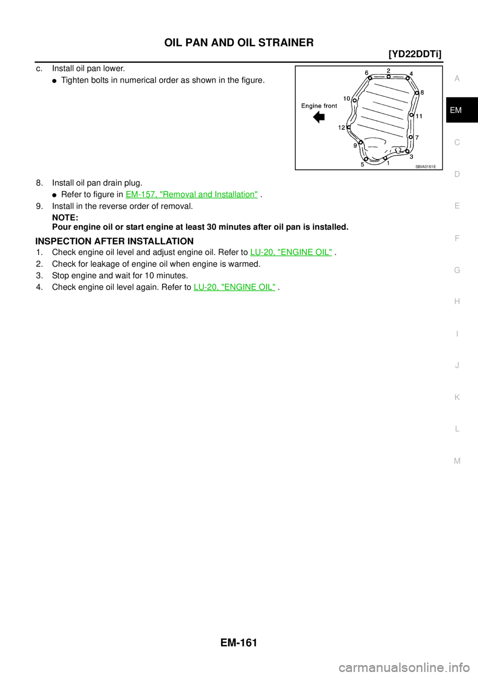
c. Install oil pan lower.
�Tighten bolts in numerical order as shown in the figure.
8. Install oil pan drain plug.
�Refer to figure in EM-157, "Removal and Installation" .
9. Install in the reverse order of removal.
NOTE:
Pour engine oil or start engine at least 30 minutes after oil pan is installed.
INSPECTION AFTER INSTALLATION
1. Check engine oil level and adjust engine oil. Refer to LU-20, "ENGINE OIL" .
2. Check for leakage of engine oil when engine is warmed.
3. Stop engine and wait for 10 minutes.
4. Check engine oil level again. Refer to LU-20, "
ENGINE OIL" .
SBIA0161E
Page 224 of 4555
EM-170
[YD22DDTi]
INJECTION TUBE AND FUEL INJECTOR
CAUTION:
�Check gutter spring in nozzle oil seal on fuel injector for missing.
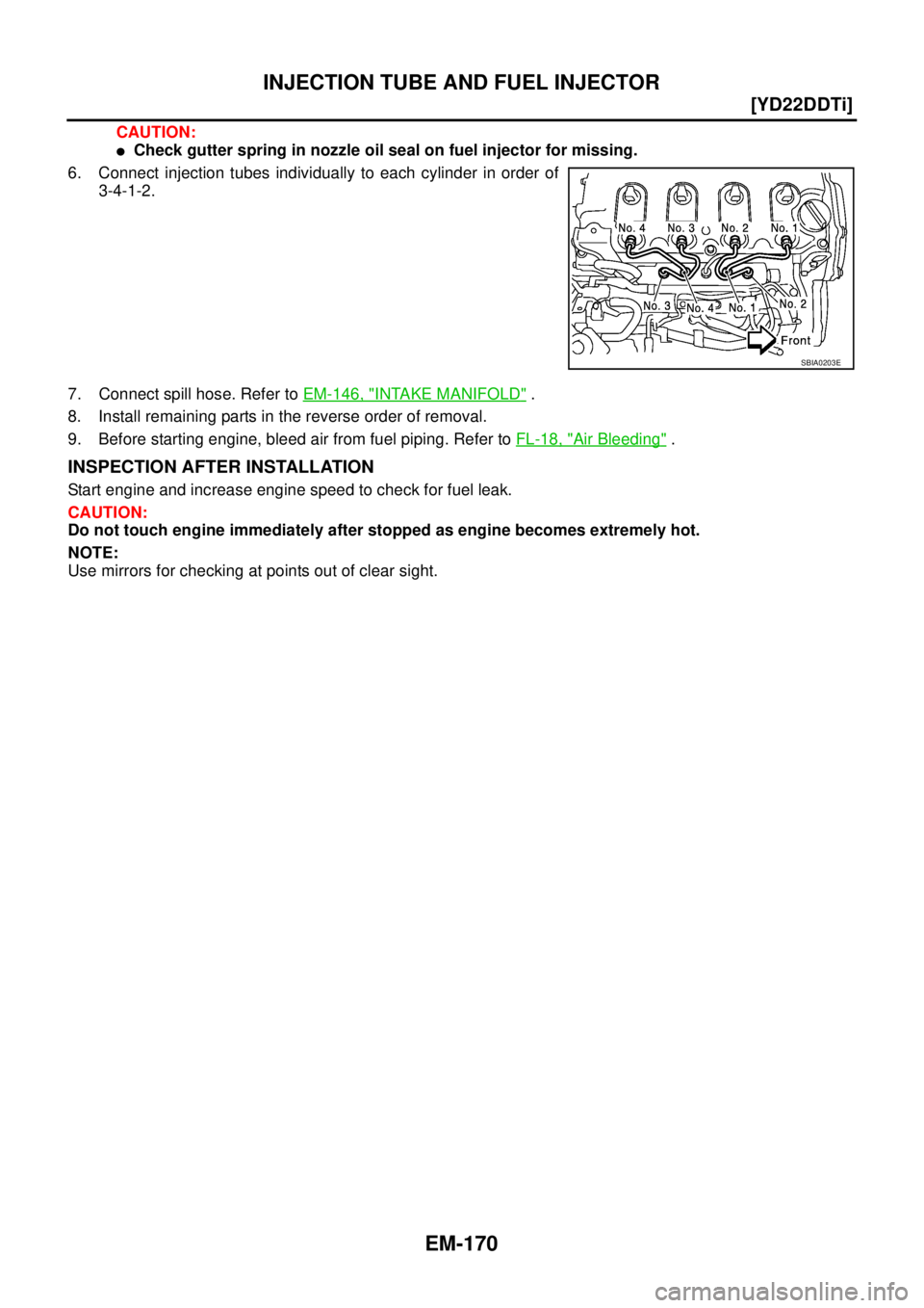
6. Connect injection tubes individually to each cylinder in order of
3-4-1-2.
7. Connect spill hose. Refer to EM-146, "
INTAKE MANIFOLD" .
8. Install remaining parts in the reverse order of removal.
9. Before starting engine, bleed air from fuel piping. Refer to FL-18, "
Air Bleeding" .
INSPECTION AFTER INSTALLATION
Start engine and increase engine speed to check for fuel leak.
CAUTION:
Do not touch engine immediately after stopped as engine becomes extremely hot.
NOTE:
Use mirrors for checking at points out of clear sight.
SBIA0203E
Page 231 of 4555
![NISSAN X-TRAIL 2005 Service Repair Manual FUEL PUMP
EM-177
[YD22DDTi]
C
D
E
F
G
H
I
J
K
L
MA
EM
11. Using the hexagon wrench (special service tool), tighten the
sprocket tightening bolt.
�When the washer of the fuel pump sprocket is removed](/manual-img/5/57403/w960_57403-230.png "NISSAN X-TRAIL 2005 Service Repair Manual FUEL PUMP
EM-177
[YD22DDTi]
C
D
E
F
G
H
I
J
K
L
MA
EM
11. Using the hexagon wrench (special service tool), tighten the
sprocket tightening bolt.
�When the washer of the fuel pump sprocket is removed")
FUEL PUMP
EM-177
[YD22DDTi]
C
D
E
F
G
H
I
J
K
L
MA
EM
11. Using the hexagon wrench (special service tool), tighten the
sprocket tightening bolt.
�When the washer of the fuel pump sprocket is removed,
install it with the marking “F” (front) facing the front of the
engine.
12. Pull out the positioning stopper pin (special service tool).
13. Install secondary timing chain. Refer to EM-193, "
Removal and Installation" .
14. Install injection tube center as follows: Refer to EM-167, "
INJECTION TUBE AND FUEL INJECTOR" .
a. Pre-set clip and insert rubber to injection tube center.
b. Pre-tight nut of injection tube center to fuel pump and fuel rail by hand. (until seal surface touched)
c. Adjust clip dimension and tight bolt for clip to intake manifold by tool.
d. Tight nut of injection tube center to fuel pump by tool.
e. Tight nut of injection tube center to fuel rail by tool.
15. Connect the harness connector to fuel pump.
16. Install fuel hoses.
17. Hereafter, install in the reverse order of removal.
18. Before starting engine, bleed air from fuel piping. Refer to FL-18, "
Air Bleeding" .
PBIC2404E
Page 233 of 4555
![NISSAN X-TRAIL 2005 Service Repair Manual ROCKER COVER
EM-179
[YD22DDTi]
C
D
E
F
G
H
I
J
K
L
MA
EM
�Loosen holding bolts in reverse order of that shown in the fig-
ure and remove.
6. Remove rocker cover gasket.
INSTALLATION
1. Apply 3.0 mm](/manual-img/5/57403/w960_57403-232.png "NISSAN X-TRAIL 2005 Service Repair Manual ROCKER COVER
EM-179
[YD22DDTi]
C
D
E
F
G
H
I
J
K
L
MA
EM
�Loosen holding bolts in reverse order of that shown in the fig-
ure and remove.
6. Remove rocker cover gasket.
INSTALLATION
1. Apply 3.0 mm")
ROCKER COVER
EM-179
[YD22DDTi]
C
D
E
F
G
H
I
J
K
L
MA
EM
�Loosen holding bolts in reverse order of that shown in the fig-
ure and remove.
6. Remove rocker cover gasket.
INSTALLATION
1. Apply 3.0 mm (0.118 in) dia. on locations shown in the figure.
�Use Genuine Liquid Gasket or equivalent.
2. Install rocker cover gasket to rocker cover.
3. Tighten holding bolts in numerical order shown in the figure.
Re-tighten to the same torque in the same order as above.
4. Install nozzle oil seal.
�Insert it straight until flange fully contacts rocker cover.
5. Install remaining parts in the reverse order of removal.
6. Before starting engine, bleed air from fuel piping. Refer to FL-18, "
Air Bleeding" .
INSPECTION AFTER INSTALLATION
Start engine and increase engine speed to check for fuel leak.
CAUTION:
Do not touch the engine immediately after stopped as engine becomes extremely hot.
NOTE:
Use mirrors for checking at points out of clear sight.
SBIA0175E
JEM248G
: 7.8 N·m (0.8 kg-m, 69 in-lb)
SBIA0175E
Page 239 of 4555
![NISSAN X-TRAIL 2005 Service Repair Manual CAMSHAFT
EM-185
[YD22DDTi]
C
D
E
F
G
H
I
J
K
L
MA
EM
�Install so that knock pins are positioned in the directions
shown in the figure.
NOTE:
Though camshaft does not stop at the location as shown in](/manual-img/5/57403/w960_57403-238.png "NISSAN X-TRAIL 2005 Service Repair Manual CAMSHAFT
EM-185
[YD22DDTi]
C
D
E
F
G
H
I
J
K
L
MA
EM
�Install so that knock pins are positioned in the directions
shown in the figure.
NOTE:
Though camshaft does not stop at the location as shown in")
CAMSHAFT
EM-185
[YD22DDTi]
C
D
E
F
G
H
I
J
K
L
MA
EM
�Install so that knock pins are positioned in the directions
shown in the figure.
NOTE:
Though camshaft does not stop at the location as shown in
the figure, for the placement of cam nose, it is generally
accepted that camshaft is placed at the same direction as
shown in the figure.
3. Install camshaft brackets.
�Completely remove any foreign material on back surfaces of camshaft brackets and top surface of cyl-
inder head.
�Install correctly, identifying brackets by the journal No. and
front mark on top surface.
4. Tighten bolts in the order shown in the figure according to the
following procedure:
a. Tighten all bolts.
�Make sure camshaft thrusting parts (on rear side) securely fit
in their mating parts on the cylinder head.
b. Tighten all bolts.
c. Tighten all bolts.
5. Install camshaft sprockets.
�Camshaft sprockets are commonly used for right side and left side.
�Align camshaft sprocket and knock pin on camshaft, and install.
�Holding the hexagonal part of camshaft with a wrench, tighten bolt securing camshaft sprocket.
6. Before installing spill tube after installing secondary timing chain, check and adjust valve clearance. Refer
to EM-185, "
Valve Clearance" .
7. Hereafter, install in the reverse order of removal.
8. Before starting engine, bleed air from fuel piping. Refer to FL-18, "
Air Bleeding" .
Va l v e C l e a r a n c eEBS00LRS
INSPECTION
�When the camshaft or parts in connection with valves are removed or replaced, and a malfunction has
occurred (poor starting, idling, or other malfunction) due to the misadjustment of the valve clearance,
inspect as follows.
�Inspect and adjust when the engine is cool (at normal temperature).
PBIC2026E
JEM175G
: 2 N·m (0.2 kg-m, 1 ft-lb)
: 6 N·m (0.6 kg-m, 4 ft-lb)
: 12.5 N·m (1.3 kg-m, 9 ft-lb)
JEM160G
Page 242 of 4555
![NISSAN X-TRAIL 2005 Service Repair Manual EM-188
[YD22DDTi]
CAMSHAFT
3. Grip camshaft with the camshaft pliers (special service tool),
then using camshaft as a support point, push adjusting shim
downward to compress valve spring.
CAUTION:
D](/manual-img/5/57403/w960_57403-241.png "NISSAN X-TRAIL 2005 Service Repair Manual EM-188
[YD22DDTi]
CAMSHAFT
3. Grip camshaft with the camshaft pliers (special service tool),
then using camshaft as a support point, push adjusting shim
downward to compress valve spring.
CAUTION:
D")
EM-188
[YD22DDTi]
CAMSHAFT
3. Grip camshaft with the camshaft pliers (special service tool),
then using camshaft as a support point, push adjusting shim
downward to compress valve spring.
CAUTION:
Do not damage camshaft, cylinder head and the outer cir-
cumference of valve lifter.
4. With valve spring in a compressed state, remove the camshaft
pliers (special service tool) by securely setting the outer circum-
ference of the valve lifter with the end of the lifter stopper (spe-
cial service tool).
�Hold the lifter stopper by hand until the shim is removed.
CAUTION:
Do not retrieve the camshaft pliers forcefully, as cam-
shaft will be damaged.
5. Move the round hole of adjusting shim to the front with the very
thin screwdriver or like that.
�When adjusting shim on valve lifter will not rotate smoothly,
restart from step 3 to release the end of the lifter stopper (spe-
cial service tool) from touching adjusting shim.
6. Remove adjusting shim from valve lifter by blowing air through
the round hole of the adjusting shim with the air gun.
CAUTION:
To prevent any remaining engine oil from being blown
around, thoroughly wipe the area clean and wear protective
goggles.
7. Remove adjusting shim by using the magnet hand.
8. Measure the thickness of adjusting shim using the micrometer.
�Measure near the center of the shim (the part that touches
camshaft).
PBIC2321E
PBIC2322E
PBIC2323E
PBIC2324E
FEM032