Page 275 of 4555
CYLINDER HEAD
EM-221
[YD22DDTi]
C
D
E
F
G
H
I
J
K
L
MA
EM
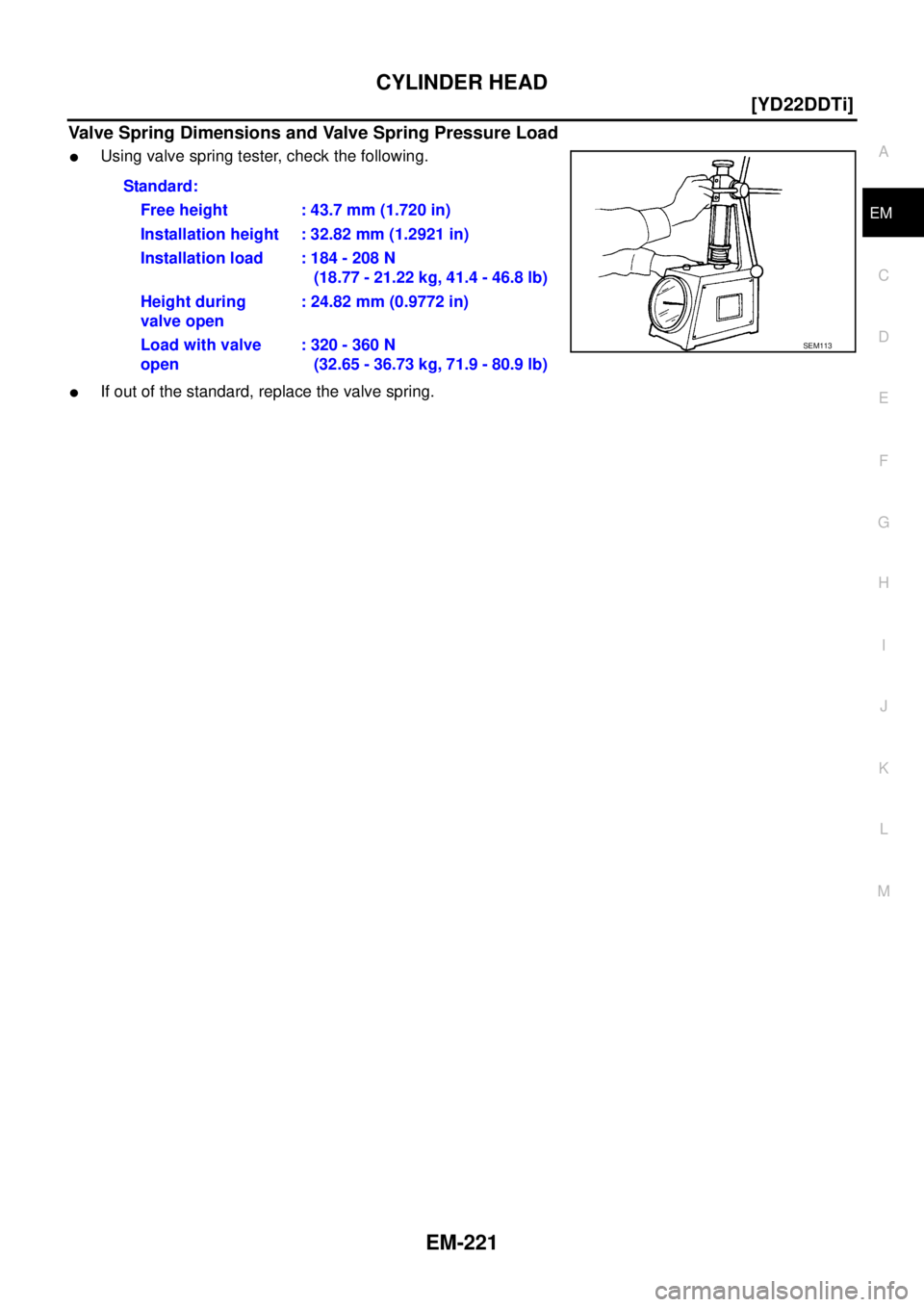
Valve Spring Dimensions and Valve Spring Pressure Load
�Using valve spring tester, check the following.
�If out of the standard, replace the valve spring.Standard:
Free height : 43.7 mm (1.720 in)
Installation height : 32.82 mm (1.2921 in)
Installation load : 184 - 208 N
(18.77 - 21.22 kg, 41.4 - 46.8 lb)
Height during
valve open: 24.82 mm (0.9772 in)
Load with valve
open: 320 - 360 N
(32.65 - 36.73 kg, 71.9 - 80.9 lb)
SEM113
Page 307 of 4555
![NISSAN X-TRAIL 2005 Service Repair Manual CYLINDER BLOCK
EM-253
[YD22DDTi]
C
D
E
F
G
H
I
J
K
L
MA
EM
MAIN BEARING OIL CLEARANCE
Method by Measurement
�Install main bearings to cylinder block and bearing cap, and
tighten the bolts to the spe](/manual-img/5/57403/w960_57403-306.png "NISSAN X-TRAIL 2005 Service Repair Manual CYLINDER BLOCK
EM-253
[YD22DDTi]
C
D
E
F
G
H
I
J
K
L
MA
EM
MAIN BEARING OIL CLEARANCE
Method by Measurement
�Install main bearings to cylinder block and bearing cap, and
tighten the bolts to the spe")
CYLINDER BLOCK
EM-253
[YD22DDTi]
C
D
E
F
G
H
I
J
K
L
MA
EM
MAIN BEARING OIL CLEARANCE
Method by Measurement
�Install main bearings to cylinder block and bearing cap, and
tighten the bolts to the specified torque. Refer to EM-235,
"ASSEMBLY" . Then, measure the inner diameter of main bear-
ings.
(Bearing clearance) = (Bearing inner diameter) − (Crankshaft
main journal diameter)
�If out of the standard, check main bearing housing inner diame-
ter and crankshaft main journal diameter, and select appropriate
main bearing to adjust clearance to specifications. Refer to EM-
244, "HOW TO SELECT MAIN BEARING" .
Method of Using Plastigage
�Remove contamination such as engine oil and dust completely
from crankshaft main journal and each bearing surface.
�Cut plastigage slightly shorter than bearing width. Place it in
crankshaft turning direction, avoiding oil holes.
�Install main bearings and bearing cap and tighten to the speci-
fied torque. Refer to EM-235, "
ASSEMBLY" for the tightening
procedure.
CAUTION:
Do not rotate crankshaft.
�Remove main bearings and bearing caps, and measure plasti-
gage width using scale on plastigage bag.
NOTE:
If out of specification, take same action mentioned in “Method by Measurement”.
CRUSH HEIGHT OF MAIN BEARING
�When bearing cap is removed after being tightened to the speci-
fied torque with main bearings installed, the tip end of bearing
must protrude. Refer to EM-235, "
ASSEMBLY" .
�If out of the standard, replace main bearings.
CRUSH HEIGHT OF CONNECTING ROD BEARING
�When connecting rod bearing cap is removed after being tight-
ened to the specified torque with connecting rod bearings
installed, the tip end of bearing must protrude. Refer to EM-235,
"ASSEMBLY" .
�If out of the standard, replace connecting rod bearings.Standard : 0.039 - 0.066 mm (0.0015 - 0.0026 in)
PBIC1644E
EM142
Standard : There must be crush height.
SEM502G
Standard : There must be crush height.
PBIC1646E
Page 311 of 4555
![NISSAN X-TRAIL 2005 Service Repair Manual SERVICE DATA AND SPECIFICATIONS (SDS)
EM-257
[YD22DDTi]
C
D
E
F
G
H
I
J
K
L
MA
EM
CAMSHAFT
Unit: mm (in)
*: Total indicator reading
Valve Lifter
Unit: mm (in)
Valve Clearance
Unit: mm (in)
*: Approx](/manual-img/5/57403/w960_57403-310.png "NISSAN X-TRAIL 2005 Service Repair Manual SERVICE DATA AND SPECIFICATIONS (SDS)
EM-257
[YD22DDTi]
C
D
E
F
G
H
I
J
K
L
MA
EM
CAMSHAFT
Unit: mm (in)
*: Total indicator reading
Valve Lifter
Unit: mm (in)
Valve Clearance
Unit: mm (in)
*: Approx")
SERVICE DATA AND SPECIFICATIONS (SDS)
EM-257
[YD22DDTi]
C
D
E
F
G
H
I
J
K
L
MA
EM
CAMSHAFT
Unit: mm (in)
*: Total indicator reading
Valve Lifter
Unit: mm (in)
Valve Clearance
Unit: mm (in)
*: Approximately 80°C (176°F)
Available Shims
Item Standard Limit
Camshaft journal oil clearance 0.045 - 0.086 (0.0018 - 0.0034)
Camshaft bracket inner diameterNo.1 30.500 - 30.521 (1.2008 - 1.2016)
— No. 2, 3, 4, 5 24.000 - 24.021 (0.9449 - 0.9457)
Camshaft journal outer diameterNo. 1 30.435 - 30.455 (1.1982 - 1.1990)
No. 2, 3, 4, 5 23.935 - 23.955 (0.9423 - 0.9431)
Camshaft runout [TIR*] — 0.02 (0.0008)
Camshaft sprocket runout [TIR*] — 0.15 (0.0059)
Camshaft end play 0.070 - 0.148 (0.0028 - 0.0058) 0.24 (0.0094)
Cam nose height “A”Intake 39.505 - 39.695 (1.5553 - 1.5628)
Exhaust 39.905 - 40.095 (1.5711 - 1.5785)
SEM671
Item Standard
Valve lifter outer diameter 29.960 - 29.975 (1.1795 - 1.1801)
Valve lifter hole diameter 30.000 - 30.021 (1.1811 - 1.1819)
Valve lifter clearance 0.025 - 0.061 (0.0010 - 0.0024)
Item Cold Hot* (Reference data)
Intake 0.24 - 0.32 (0.0094 - 0.0126) 0.274 - 0.386 (0.0108 - 0.0152)
Exhaust 0.26 - 0.34 (0.0102 - 0.0134) 0.308 - 0.432 (0.0121 - 0.0170)
Stamped mark Thickness mm (in)
2.10 2.10 (0.0827)
2.12 2.12 (0.0835)
2.14 2.14 (0.0843)
2.16 2.16 (0.0850)
2.18 2.18 (0.0858)
2.20 2.20 (0.0866)
2.22 2.22 (0.0874)
2.24 2.24 (0.0882)
Page 315 of 4555
SERVICE DATA AND SPECIFICATIONS (SDS)
EM-261
[YD22DDTi]
C
D
E
F
G
H
I
J
K
L
MA
EM
Valve Seat
Unit: mm (in)
Item Standard Service
Cylinder head seat recess diameter (D)Intake 30.000 - 30.016 (1.1811 - 1.1817) 30.500 - 30.516 (1.2008 - 1.2014)
Exhaust 29.000 - 29.016 (1.1417 - 1.1424) 29.500 - 29.516 (1.1614 - 1.1620)
Valve seat interference fitIntake 0.064 - 0.100 (0.0025 - 0.0039)
Exhaust 0.064 - 0.096 (0.0025 - 0.0038)
Valve seat outer diameter (d)Intake 30.080 - 30.100 (1.1842 - 1.1850) 30.580 - 30.600 (1.2039 - 1.2047)
Exhaust 29.080 - 29.096 (1.1449 - 1.1455) 29.580 - 29.596 (1.1646 - 1.1652)
Height (h)Intake 7.0 - 7.1 (0.276 - 0.280) 6.60 - 6.70 (0.2598 - 0.2638)
Exhaust 6.7 - 6.8 (0.264 - 0.268) 6.3 - 6.4 (0.248 - 0.252)
SEM546G
JEM253G
Page 316 of 4555
![NISSAN X-TRAIL 2005 Service Repair Manual EM-262
[YD22DDTi]
SERVICE DATA AND SPECIFICATIONS (SDS)
Valve Spring
CYLINDER BLOCK
Unit: mm (in) Depth (H)Intake 8.83 - 9.13 (0.3476 - 0.3594)
Exhaust 9.06 - 9.36 (0.3567 - 0.3685)
Projection (L)In](/manual-img/5/57403/w960_57403-315.png "NISSAN X-TRAIL 2005 Service Repair Manual EM-262
[YD22DDTi]
SERVICE DATA AND SPECIFICATIONS (SDS)
Valve Spring
CYLINDER BLOCK
Unit: mm (in) Depth (H)Intake 8.83 - 9.13 (0.3476 - 0.3594)
Exhaust 9.06 - 9.36 (0.3567 - 0.3685)
Projection (L)In")
EM-262
[YD22DDTi]
SERVICE DATA AND SPECIFICATIONS (SDS)
Valve Spring
CYLINDER BLOCK
Unit: mm (in) Depth (H)Intake 8.83 - 9.13 (0.3476 - 0.3594)
Exhaust 9.06 - 9.36 (0.3567 - 0.3685)
Projection (L)Intake 36.53 - 36.98 (1.4382 - 1.4559)
Exhaust 36.53 - 37.01 (1.4382 - 1.4571)
Valve spring square mm (in) 1.9 (0.075)
Free height mm (in) 43.7 (1.720)
Pressure N (kg, lb) at height mm (in) 184 - 208 (18.77 - 21.22, 41.4 - 46.8) at 32.82 (1.2921)
Height during valve open mm (in) 24.82 (0.9772)
Load with valve open N (kg, lb) 320 - 360 (32.65 - 36.73, 71.9 - 80.9)
Top surface distortionStandard Less than 0.03 (0.0012)
Limit 0.1 (0.004)
Cylinder bore Inner diameterStandardGrade No. 1 86.000 - 86.010 (3.3858 - 3.3862)
Grade No. 2 86.010 - 86.020 (3.3862 - 3.3866)
Grade No. 3 86.020 - 86.030 (3.3866 - 3.3870)
Wear limit 0.20 (0.008)
Out-of-round (Difference
between X and Y)
Limit0.015 (0.0006)
Taper (Difference between A
and C)0.010 (0.0004)
Main bearing housing inner diameter (Without bearing) 66.654 - 66.681 (2.6242 - 2.6252)
Difference in inner diameter
between cylindersLimit 0.05 (0.0020)
JEM207G
Page 374 of 4555
CO-18
[QR]
RADIATOR (ALUMINUM TYPE)
4. Make sure that the rim is completely crimped down.
5. Make sure that there is no leakage.
Refer to CO-18, "
INSPECTION" .
INSPECTION
1. Apply pressure with radiator cap tester adapter (special service
tool) and radiator cap tester (commercial service tool).
WARNING:
To prevent the risk of hose coming undone while under
pressure, securely fasten it down with hose clamp.
CAUTION:
Attach hose to A/T fluid cooler to seal its inlet and outlet.
(A/T models)
2. Check for leakage by soaking radiator in water container with
the testing pressure applied.Standard height “H” : 8.0 - 8.4 mm (0.315 - 0.331 in)
SLC554A
Testing pressure
: 157 kPa (1.57 bar, 1.6 kg/cm
2 , 23 psi)
SLC933
SLC934
Page 397 of 4555
RADIATOR (ALUMINUM TYPE)
CO-41
[YD22DDTi]
C
D
E
F
G
H
I
J
K
L
MA
CO
2. Install sealing rubber while pushing it with fingers.
CAUTION:
Be careful not to twist sealing rubber.
3. Caulk tank in numerical order as shown in the figure with radia-
tor plate pliers A (special service tool).
�Use pliers in the locations where radiator plate pliers A cannot
be used.
4. Make sure that the rim is completely crimped down.
5. Make sure that there is no leakage.
Refer to CO-42, "
INSPECTION" .
SLC917A
SLC904
PBIC2076E
SLC897
Standard height “H”: 8.0 - 8.4 mm (0.315 - 0.331 in)
SLC554A
Page 548 of 4555
EC-144
[QR (WITH EURO-OBD)]
DTC P0031, P0032 HO2S1 HEATER
6. CHECK INTERMITTENT INCIDENT
Refer to EC-124, "
TROUBLE DIAGNOSIS FOR INTERMITTENT INCIDENT" .
>>INSPECTION END
Component InspectionEBS010MR
HEATED OXYGEN SENSOR 1 HEATER
1. Check resistance between HO2S1 terminals as follows.
2. If NG, replace heated oxygen sensor 1.
CAUTION:
�Discard any heated oxygen sensor which has been dropped
from a height of more than 0.5 m (19.7 in) onto a hard sur-
face such as a concrete floor; use a new one.
�Before installing new oxygen sensor, clean exhaust system
threads using Oxygen Sensor Thread Cleaner tool and
approved anti-seize lubricant.
Removal and InstallationEBS010MS
HEATED OXYGEN SENSOR 1
Refer to EM-25, "EXHAUST MANIFOLD AND THREE WAY CATALYST" .
Terminal No. Resistance
1 and 4 3.3 - 4.0 Ω [at 25°C (77°F)]
2 and 1, 3, 4
∞ Ω
(Continuity should not exist)
3 and 1, 2, 4
PBIB0542E
![NISSAN X-TRAIL 2005 Service Repair Manual SERVICE DATA AND SPECIFICATIONS (SDS)
EM-261
[YD22DDTi]
C
D
E
F
G
H
I
J
K
L
MA
EM
Valve Seat
Unit: mm (in)
Item Standard Service
Cylinder head seat recess diameter (D)Intake 30.000 - 30.016 (1.1811](/manual-img/5/57403/w960_57403-314.png "NISSAN X-TRAIL 2005 Service Repair Manual SERVICE DATA AND SPECIFICATIONS (SDS)
EM-261
[YD22DDTi]
C
D
E
F
G
H
I
J
K
L
MA
EM
Valve Seat
Unit: mm (in)
Item Standard Service
Cylinder head seat recess diameter (D)Intake 30.000 - 30.016 (1.1811")
![NISSAN X-TRAIL 2005 Service Repair Manual CO-18
[QR]
RADIATOR (ALUMINUM TYPE)
4. Make sure that the rim is completely crimped down.
5. Make sure that there is no leakage.
Refer to CO-18, "
INSPECTION" .
INSPECTION
1. Apply pressure with rad](/manual-img/5/57403/w960_57403-373.png "NISSAN X-TRAIL 2005 Service Repair Manual CO-18
[QR]
RADIATOR (ALUMINUM TYPE)
4. Make sure that the rim is completely crimped down.
5. Make sure that there is no leakage.
Refer to CO-18, \"
INSPECTION\" .
INSPECTION
1. Apply pressure with rad")
![NISSAN X-TRAIL 2005 Service Repair Manual RADIATOR (ALUMINUM TYPE)
CO-41
[YD22DDTi]
C
D
E
F
G
H
I
J
K
L
MA
CO
2. Install sealing rubber while pushing it with fingers.
CAUTION:
Be careful not to twist sealing rubber.
3. Caulk tank in numeric](/manual-img/5/57403/w960_57403-396.png "NISSAN X-TRAIL 2005 Service Repair Manual RADIATOR (ALUMINUM TYPE)
CO-41
[YD22DDTi]
C
D
E
F
G
H
I
J
K
L
MA
CO
2. Install sealing rubber while pushing it with fingers.
CAUTION:
Be careful not to twist sealing rubber.
3. Caulk tank in numeric")
![NISSAN X-TRAIL 2005 Service Repair Manual EC-144
[QR (WITH EURO-OBD)]
DTC P0031, P0032 HO2S1 HEATER
6. CHECK INTERMITTENT INCIDENT
Refer to EC-124, "
TROUBLE DIAGNOSIS FOR INTERMITTENT INCIDENT" .
>>INSPECTION END
Component InspectionEBS010](/manual-img/5/57403/w960_57403-547.png "NISSAN X-TRAIL 2005 Service Repair Manual EC-144
[QR (WITH EURO-OBD)]
DTC P0031, P0032 HO2S1 HEATER
6. CHECK INTERMITTENT INCIDENT
Refer to EC-124, \"
TROUBLE DIAGNOSIS FOR INTERMITTENT INCIDENT\" .
>>INSPECTION END
Component InspectionEBS010")