Page 2155 of 4555

CL-19
D
E
F
G
H
I
J
K
L
MA
B
CL
SERVICE DATA AND SPECIFICATIONS (SDS)PFP:00030
Clutch Control SystemECS008BH
Clutch Master CylinderECS008BI
Clutch Operating Cyl")
SERVICE DATA AND SPECIFICATIONS (SDS)
CL-19
D
E
F
G
H
I
J
K
L
MA
B
CL
SERVICE DATA AND SPECIFICATIONS (SDS)PFP:00030
Clutch Control SystemECS008BH
Clutch Master CylinderECS008BI
Clutch Operating CylinderECS008BJ
Clutch DiscECS008BK
Clutch CoverECS008BL
Type of clutch controlHydraulic
Inner diameter15.87 mm (5/8 in)
Inner diameter19.05 mm (3/4 in)
Engine type QR20DE QR25DE YD22DDTi
Model240
Facing size
(outer dia. x inner dia. x thickness)240 mm x 160 mm x 3.5 mm (9.45 in x 6.30 in x 0.138 in)240 mm x 170 mm x 3.5 mm
(9.45 in x 6.69 in x 0.138 in)
Thickness of disc assembly with load7.90 - 8.30 mm (0.3110 - 0.3268 in) with 5,688 N (580 kg,
1,279 lb)7.70 - 8.10 mm (0.303 -
0.319 in) with 7,845N (800
kg, 1,764 lb)
Wear limit of facing surface to rivet head 0.3 mm (0.012 in)
Runout limit/diameter of the area to be
measured1.0 mm (0.039 in) / 230 mm (9.06 in) dia.
Maximum spline backlash
(at outer edge of disc)1.0 mm (0.039 in)
Engine type QR20DE QR25DE YD22DDTi
Model 240 250
Set-load 4,903 N (500 kg, 1,103 lb) 5,884 N (600 kg, 1,323 lb) 7,600 N (775 kg, 1,708 lb)
Diaphragm spring lever height 37.0 - 39.0 mm (1.457 - 1.535 in)
Uneven limit diaphragm spring toe height 0.7 mm (0.028 in) or less
Page 2243 of 4555

MAINSHAFT AND GEARS
MT-87
D
E
F
G
H
I
J
K
L
MA
B
MT
16. Select 6th main adjusting shim and then install it onto mainshaft.
�Calculate thickness “S” of 6th main adjusting shim following
the procedure below so that end play dimension between 6th
main gear and mainshaft rear bearing becomes the dimen-
sion shown below. Refer to MT-107, "
6TH MAIN GEAR
ADJUSTING SHIM" .
CAUTION:
Only one adjusting shim can be selected.
a. Using height gauge, measure dimension “S
1 ” and “S2 ”.
b. Install selected 6th main adjusting shim to mainshaft.
17. Press in mainshaft rear bearing using the drifts.
18. Install mainshaft C-ring onto mainshaft, and check that end play
of mainshaft rear bearing satisfies the standard value.
�If measurement is outside the standard range, reselect main-
shaft C-ring. Refer to MT-105, "
MAINSHAFT C-RING" . End play: 0 - 0.1 mm (0 - 0.004 in)
Dimension“S” = (S
1 - S2 ) - End play
S: Thickness of adjusting shim
S
1 : Dimension from mainshaft standard face to
mainshaft rear bearing press-fit end face
S
2 : Dimension from mainshaft standard face to
6th main gear end face
SCIA0995E
SCIA0978E
End play standard value : 0 - 0.06 mm (0 - 0.0024 in)
SCIA0979E
Page 2776 of 4555
AT-512
[ALL]
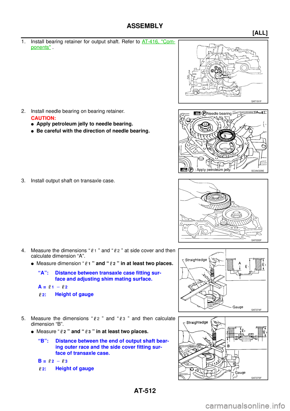
ASSEMBLY
1. Install bearing retainer for output shaft. Refer to AT- 4 1 6 , "Com-
ponents" .
2. Install needle bearing on bearing retainer.
CAUTION:
�Apply petroleum jelly to needle bearing.
�Be careful with the direction of needle bearing.
3. Install output shaft on transaxle case.
4. Measure the dimensions “
1 ” and “2 ” at side cover and then
calculate dimension “A”.
�Measure dimension “1 ” and “2 ” in at least two places.
5. Measure the dimensions “
2 ” and “3 ” and then calculate
dimension “B”.
�Measure “2 ” and “3 ” in at least two places.
SAT191F
SCIA4329E
SAT035F
“A”: Distance between transaxle case fitting sur-
face and adjusting shim mating surface.
A =
1 − 2
2
:Height of gauge
SAT374F
“B”: Distance between the end of output shaft bear-
ing outer race and the side cover fitting sur-
face of transaxle case.
B =
2 − 3
2
:Height of gauge
SAT375F
Page 2865 of 4555
TRANSFER ASSEMBLY
TF-61
C
E
F
G
H
I
J
K
L
MA
B
TF
6. If tooth contact is poorly adjusted, adjust pinion height (dimen-
sion X) in the following manner.
SDIA0520E
SDIA0517E
Page 2910 of 4555
RFD-20
REAR FINAL DRIVE ASSEMBLY
6. Rotate the drive gear back and forth in several times, check
drive pinion gear to drive gear tooth contact.
CAUTION:
Check tooth contact on drive side and reverse side.
7. If the tooth contact is improperly adjusted, follow the procedure
below to adjust the pinion height (dimension X in the figure).
SDIA0570E
SDIA2549E
SDIA0517E
Page 2965 of 4555

FSU-1
FRONT SUSPENSION
E SUSPENSION
CONTENTS
C
D
F
G
H
I
J
K
L
M
SECTION FSU
A
B
FSU
FRONT SUSPENSION
PRECAUTIONS .......................................................... 2
Caution ..................................................................... 2
PREPARATION ........................................................... 3
Special Service Tools (SST) ..................................... 3
Commercial Service Tools ........................................ 3
NOISE, VIBRATION AND HARSHNESS (NVH)
TROUBLESHOOTING ................................................ 4
NVH Troubleshooting Chart ..................................... 4
FRONT SUSPENSION ASSEMBLY ........................... 5
Components ............................................................. 5
On-Vehicle Inspection and Service .......................... 6
LOOSENESS, BACKLASH AND DAMAGE OF
MOUNTING PARTS AND CONNECTIONS .......... 6
Wheel Alignment ...................................................... 6
DESCRIPTION ...................................................... 6
PRELIMINARY INSPECTION ............................... 6
INSPECTION OF CAMBER, CASTER, AND
KINGPIN INCLINATION ANGLES ........................ 6
STEERING ANGLE INSPECTION ........................ 7
COIL SPRING AND SHOCK ABSORBER ................. 8
Removal and Installation .......................................... 8
REMOVAL ............................................................. 8INSTALLATION ..................................................... 8
Disassembly and Assembly ...................................... 8
DISASSEMBLY ..................................................... 8
INSPECTION AFTER DISASSEMBLY .................. 8
ASSEMBLY ........................................................... 9
TRANSVERSE LINK ................................................. 10
Removal and Installation ........................................ 10
REMOVAL ........................................................... 10
INSPECTION AFTER REMOVAL ....................... 10
INSTALLATION ................................................... 10
STABILIZER BAR ..................................................... 11
Removal and Installation ........................................ 11
REMOVAL ........................................................... 11
INSPECTION AFTER REMOVAL ....................... 11
INSTALLATION ................................................... 11
FRONT SUSPENSION MEMBER ............................. 12
Removal and Installation ........................................ 12
REMOVAL ........................................................... 12
INSTALLATION ................................................... 12
SERVICE DATA AND SPECIFICATIONS (SDS) ...... 13
General Specification ............................................. 13
Wheel Alignment (Unladen) .................................... 13
Ball Joint ................................................................. 13
Wheelarch Height (Unladen) .................................. 13
Page 2970 of 4555

FSU-6
FRONT SUSPENSION ASSEMBLY
On-Vehicle Inspection and ServiceEES00072
LOOSENESS, BACKLASH AND DAMAGE OF MOUNTING PARTS AND CONNECTIONS
Lift vehicle and inspect the following:
�Check mounting point of each component for looseness, backlash and damage.
�Check lower ball joint end play.
1. Attach a dial gauge so that the contact rests on the brake caliper.
2. Set front wheels in a straight-ahead position. Do not depress brake pedal.
3. Measure axial end play by placing an iron pry bar or something similar between transverse link and steer-
ing knuckle.
CAUTION:
Be careful not to damage ball joint boot.
4. If axial end play is outside the standard, remove transverse link and check lower ball joint.
Wheel AlignmentEES00073
DESCRIPTION
�Measure wheel alignment under unladen conditions. “Unladen conditions” means that fuel, coolant, and
lubricant are full. However, spare tyre, jack, and hand tools should be unloaded.
PRELIMINARY INSPECTION
1. Check the tyre for improper air pressure and wear.
2. Check road wheels for runout.
3. Check wheel bearing axial endplay.
4. Check lower ball joint axial endplay.
5. Check strut operation.
6. Check each mounting point of axle and suspension for looseness and deformation.
7. Check each link and arm for cracks, deformation, and other damage.
8. Check the vehicle posture.
INSPECTION OF CAMBER, CASTER, AND KINGPIN INCLINATION ANGLES
�Camber, caster, and kingpin inclination angles cannot be adjusted.
�Before inspection, mount front wheels onto turning radius gauge. Mount rear wheels onto a stand that has
same height so the vehicle will remain horizontal.
1. Measure camber, caster and kingpin inclination of both right and
left wheels with a suitable alignment gauge.
2. If camber, caster or kingpin inclination is not within specification,
inspect front suspension parts. Replace dam-aged or worn out
parts.
1. Upper mounting plate 2. Strut spacer 3. Strut mounting insulator
4. Strut mounting insulator bracket 5. Thrust bearing 6. Spring upper seat
7. Upper rubber seat 8. Bound bumper 9. Coil spring
10. Strut 11. Axle assembly 12. Cotter pin
13. Clamp 14. Bushing 15. Stabilizer bar
16. Washer 17. Connecting rod 18. Suspension member
19. Member pin stay 20. Transverse link 21. Steering stopper bracket
Axial endplay : 0 mm (0 in)
Camber, caster and kingpin inclination:
FSU-13, "
SERVICE DATA AND SPECIFICATIONS
(SDS)"
SRA096A
Page 2971 of 4555

FRONT SUSPENSION ASSEMBLY
FSU-7
C
D
F
G
H
I
J
K
L
MA
B
FSU
To e - i n
Measure toe-in using the following procedure.
WARNING:
�Always perform the following procedure on a flat surface.
�Make sure that no person is in front of the vehicle before
pushing it.
1. Bounce front of vehicle up and down to stabilize the posture.
2. Push the vehicle straight ahead about 5 m (16 ft).
3. Put a mark on base line of tread (rear side) of both tyre at the
same height as hub center. These are measuring points.
4. Measure distance “A” (rear side).
5. Push the vehicle slowly ahead to rotate the wheels 180degrees
(1/2 turn).
If the wheels have rotated more than 180 degrees (1/2 turn), try
the above procedure again from the beginning. Never push
vehicle backward.
6. Measure distance “B” (front side).
STEERING ANGLE INSPECTION
1. Set wheels in straight-ahead position. Move vehicle to set front wheels on turning radius gauge.
2. Turn steering wheel fully to right and left, and measure steering angle. Refer to PS-44, "
SERVICE DATA
AND SPECIFICATIONS (SDS)" .
AFA050
To ta l t o e - i n :
FSU-13, "
SERVICE DATA AND SPECIFICATIONS
(SDS)"SFA234AC
 in the following manner.
SDIA0520E
SDIA0517E")
