Page 3619 of 4555
POWER DOOR LOCK SYSTEM
BL-37
C
D
E
F
G
H
J
K
L
MA
B
BL
Rear Door Lock Actuator RH CheckEIS004DL
1. CHECK DOOR LOCK SIGNAL
1. Turn ignition switch OFF.
2. Disconnect rear door lock actuator RH connector.
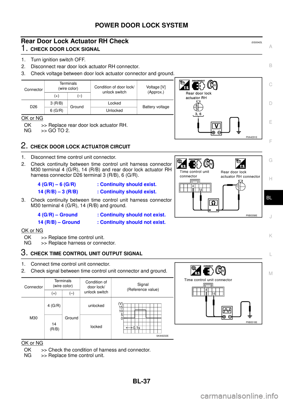
3. Check voltage between door lock actuator connector and ground.
OK or NG
OK >> Replace rear door lock actuator RH.
NG >> GO TO 2.
2. CHECK DOOR LOCK ACTUATOR CIRCUIT
1. Disconnect time control unit connector.
2. Check continuity between time control unit harness connector
M30 terminal 4 (G/R), 14 (R/B) and rear door lock actuator RH
harness connector D26 terminal 3 (R/B), 6 (G/R).
3. Check continuity between time control unit harness connector
M30 terminal 4 (G/R), 14 (R/B) and ground.
OK or NG
OK >> Replace time control unit.
NG >> Replace harness or connector.
3. CHECK TIME CONTROL UNIT OUTPUT SIGNAL
1. Connect time control unit connector.
2. Check signal between time control unit connector and ground.
OK or NG
OK >> Check the condition of harness and connector.
NG >> Replace time control unit.
ConnectorTerminals
(wire color)Condition of door lock/
unlock switchVoltage [V]
(Approx.)
(+) (–)
D263 (R/B)
GroundLocked
Battery voltage
6 (G/R) Unlocked
PIIA4291E
4 (G/R) – 6 (G/R) : Continuity should exist.
14 (R/B) – 3 (R/B) : Continuity should exist.
4 (G/R) – Ground : Continuity should not exist.
14 (R/B) – Ground : Continuity should not exist.
PIIB0358E
ConnectorTerminals
(wire color)Condition of
door lock/
unlock switchSignal
(Reference value)
(+) (–)
M304 (G/R)
Groundunlocked
14
(R/B)locked
PIIB0518E
SKIA9232E
Page 3620 of 4555
BL-38
POWER DOOR LOCK SYSTEM
Back Door Lock Actuator CheckEIS004DM
1. CHECK DOOR LOCK SIGNAL
1. Turn ignition switch OFF.
2. Disconnect back door lock actuator connector.
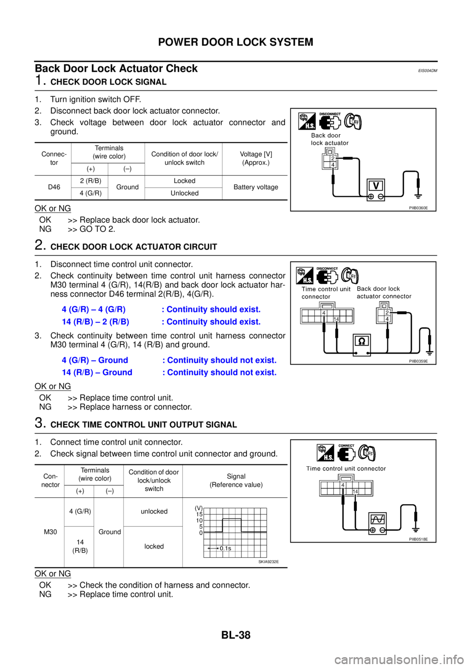
3. Check voltage between door lock actuator connector and
ground.
OK or NG
OK >> Replace back door lock actuator.
NG >> GO TO 2.
2. CHECK DOOR LOCK ACTUATOR CIRCUIT
1. Disconnect time control unit connector.
2. Check continuity between time control unit harness connector
M30 terminal 4 (G/R), 14(R/B) and back door lock actuator har-
ness connector D46 terminal 2(R/B), 4(G/R).
3. Check continuity between time control unit harness connector
M30 terminal 4 (G/R), 14 (R/B) and ground.
OK or NG
OK >> Replace time control unit.
NG >> Replace harness or connector.
3. CHECK TIME CONTROL UNIT OUTPUT SIGNAL
1. Connect time control unit connector.
2. Check signal between time control unit connector and ground.
OK or NG
OK >> Check the condition of harness and connector.
NG >> Replace time control unit.
Connec-
torTerminals
(wire color)Condition of door lock/
unlock switchVoltage [V]
(Approx.)
(+) (–)
D462 (R/B)
GroundLocked
Battery voltage
4 (G/R) Unlocked
PIIB0360E
4 (G/R) – 4 (G/R) : Continuity should exist.
14 (R/B) – 2 (R/B) : Continuity should exist.
4 (G/R) – Ground : Continuity should not exist.
14 (R/B) – Ground : Continuity should not exist.
PIIB0359E
Con-
nectorTerminals
(wire color)Condition of door
lock/unlock
switchSignal
(Reference value)
(+) (–)
M304 (G/R)
Groundunlocked
14
(R/B)locked
PIIB0518E
SKIA9232E
Page 3621 of 4555
POWER DOOR LOCK SYSTEM
BL-39
C
D
E
F
G
H
J
K
L
MA
B
BL
Door Switch CheckEIS004DN
1. CHECK FRONT DOOR SWITCH INPUT SIGNAL
1. Turn ignition switch OFF.
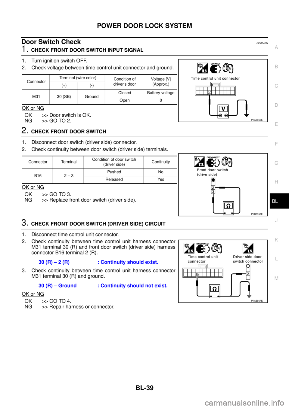
2. Check voltage between time control unit connector and ground.
OK or NG
OK >> Door switch is OK.
NG >> GO TO 2.
2. CHECK FRONT DOOR SWITCH
1. Disconnect door switch (driver side) connector.
2. Check continuity between door switch (driver side) terminals.
OK or NG
OK >> GO TO 3.
NG >> Replace front door switch (driver side).
3. CHECK FRONT DOOR SWITCH (DRIVER SIDE) CIRCUIT
1. Disconnect time control unit connector.
2. Check continuity between time control unit harness connector
M31 terminal 30 (R) and front door switch (driver side) harness
connector B16 terminal 2 (R).
3. Check continuity between time control unit harness connector
M31 terminal 30 (R) and ground.
OK or NG
OK >> GO TO 4.
NG >> Repair harness or connector.
ConnectorTerminal (wire color)
Condition of
driver's doorVoltage [V]
(Approx.)
(+) (-)
M31 30 (SB) GroundClosed Battery voltage
Open 0
PIIA8665E
Connector TerminalCondition of door switch
(driver side)Continuity
B16 2 – 3Pushed No
Released Yes
PIIB0353E
30 (R) – 2 (R) : Continuity should exist.
30 (R) – Ground : Continuity should not exist.
PIIA8667E
Page 3622 of 4555
BL-40
POWER DOOR LOCK SYSTEM
4. CHECK DOOR SWITCH (DRIVER SIDE) GROUND CIRCUIT
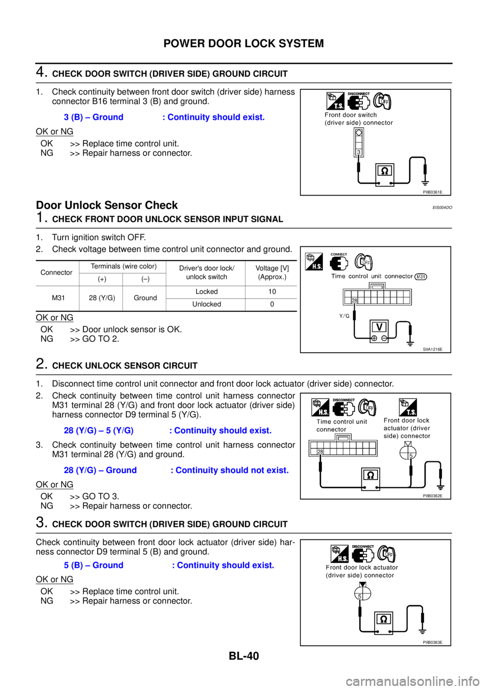
1. Check continuity between front door switch (driver side) harness
connector B16 terminal 3 (B) and ground.
OK or NG
OK >> Replace time control unit.
NG >> Repair harness or connector.
Door Unlock Sensor CheckEIS004DO
1. CHECK FRONT DOOR UNLOCK SENSOR INPUT SIGNAL
1. Turn ignition switch OFF.
2. Check voltage between time control unit connector and ground.
OK or NG
OK >> Door unlock sensor is OK.
NG >> GO TO 2.
2. CHECK UNLOCK SENSOR CIRCUIT
1. Disconnect time control unit connector and front door lock actuator (driver side) connector.
2. Check continuity between time control unit harness connector
M31 terminal 28 (Y/G) and front door lock actuator (driver side)
harness connector D9 terminal 5 (Y/G).
3. Check continuity between time control unit harness connector
M31 terminal 28 (Y/G) and ground.
OK or NG
OK >> GO TO 3.
NG >> Repair harness or connector.
3. CHECK DOOR SWITCH (DRIVER SIDE) GROUND CIRCUIT
Check continuity between front door lock actuator (driver side) har-
ness connector D9 terminal 5 (B) and ground.
OK or NG
OK >> Replace time control unit.
NG >> Repair harness or connector.3 (B) – Ground : Continuity should exist.
PIIB0361E
ConnectorTerminals (wire color)
Driver's door lock/
unlock switchVoltage [V]
(Approx.)
(+) (–)
M31 28 (Y/G) GroundLocked 10
Unlocked 0
SIIA1216E
28 (Y/G) – 5 (Y/G) : Continuity should exist.
28 (Y/G) – Ground : Continuity should not exist.
PIIB0362E
5 (B) – Ground : Continuity should exist.
PIIB0363E
Page 3623 of 4555
POWER DOOR LOCK SYSTEM
BL-41
C
D
E
F
G
H
J
K
L
MA
B
BL
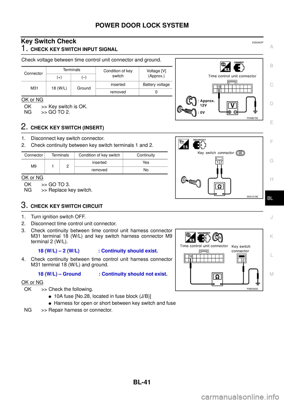
Key Switch CheckEIS004DP
1. CHECK KEY SWITCH INPUT SIGNAL
Check voltage between time control unit connector and ground.
OK or NG
OK >> Key switch is OK.
NG >> GO TO 2.
2. CHECK KEY SWITCH (INSERT)
1. Disconnect key switch connector.
2. Check continuity between key switch terminals 1 and 2.
OK or NG
OK >> GO TO 3.
NG >> Replace key switch.
3. CHECK KEY SWITCH CIRCUIT
1. Turn ignition switch OFF.
2. Disconnect time control unit connector.
3. Check continuity between time control unit harness connector
M31 terminal 18 (W/L) and key switch harness connector M9
terminal 2 (W/L).
4. Check continuity between time control unit harness connector
M31 terminal 18 (W/L) and ground.
OK or NG
OK >> Check the following.
�10A fuse [No.28, located in fuse block (J/B)]
�Harness for open or short between key switch and fuse
NG >> Repair harness or connector.
ConnectorTe r m i n a l s
Condition of key
switchVoltage [V]
(Approx.)
(+) (–)
M31 18 (W/L) Groundinserted Battery voltage
removed 0
PIIA8670E
Connector Terminals Condition of key switch Continuity
M9 1 2inserted Yes
removed No
SIIA1219E
18 (W/L) – 2 (W/L) : Continuity should exist.
18 (W/L) – Ground : Continuity should not exist.
PIIB0364E
Page 3635 of 4555
POWER DOOR LOCK — SUPER LOCK —
BL-53
C
D
E
F
G
H
J
K
L
MA
B
BL
Trouble DiagnosesEIS001R9
PRELIMINARY CHECK
After performing preliminary check, go to SYMPTOM CHART.
SIIA2239E
Page 3636 of 4555

BL-54
POWER DOOR LOCK — SUPER LOCK —
SYMPTOM CHART
NOTE:
Before starting trouble diagnoses below, perform preliminary check.
Symptom numbers in the symptom chart correspond with those of Preliminary check.
Symptom Malfunctioning systemReference
page
SYMPTOM 1
Power door lock does not operate using any switchPower supply and ground circuit checkBL-55
Front door lock actuator check (Driver side)BL-60
Front door lock actuator check (Passenger side)BL-61
Rear door lock actuator check LH BL-62
Rear door lock actuator check RHBL-63
Back door lock actuator checkBL-64
If above systems are OK, replace time control unit. —
SYMPTOM 2
Power door lock does not operate with lock/unlock
switch.Door lock/unlock switch checkBL-56
If above system is OK, replace time control unit. —
SYMPTOM 3
Power door lock does not operate with door key cylinder
switch.Door key cylinder switch checkBL-58
If above system is OK, replace time control unit. —
SYMPTOM 4
Specific door lock actuator does not operate.Front door lock actuator check (Driver side)BL-60
Front door lock actuator check (Passenger side)BL-61
Rear door lock actuator check LH BL-62
Rear door lock actuator check RHBL-63
Back door lock actuator checkBL-64
If above system is OK, replace time control unit. —
SYMPTOM 5
Super lock cannot be set by door key cylinder.Door key cylinder switch checkBL-58
Super lock actuator check (Driver side)BL-68
Super lock actuator check (Passenger side)BL-69
Super lock actuator check rear LHBL-70
Super lock actuator check rear RHBL-71
Key switch checkBL-67
Ignition switch “ON” circuit checkBL-73
If above systems are OK, replace time control unit. —
SYMPTOM 6
*Super lock cannot be released by door key cylinder.Door key cylinder switch checkBL-58
Super lock actuator check (Driver side)BL-68
Super lock actuator check (Passenger side)BL-69
Super lock actuator check rear LHBL-70
Super lock actuator check rear RHBL-71
If above systems are OK, replace time control unit. —
SYMPTOM 7
*Super lock cannot be released by ignition key switch.
(Signal from NATS IMMU)Super lock actuator check (Driver side)BL-68
Super lock actuator check (Passenger side)BL-69
Super lock actuator check rear LHBL-70
Super lock actuator check rear RHBL-71
NATS release signal checkBL-72
Ignition switch “ON” circuit checkBL-73
If above systems are “OK”, replace time control unit. —
Page 3637 of 4555
POWER DOOR LOCK — SUPER LOCK —
BL-55
C
D
E
F
G
H
J
K
L
MA
B
BL
*:Make sure the power door lock system operates properly.
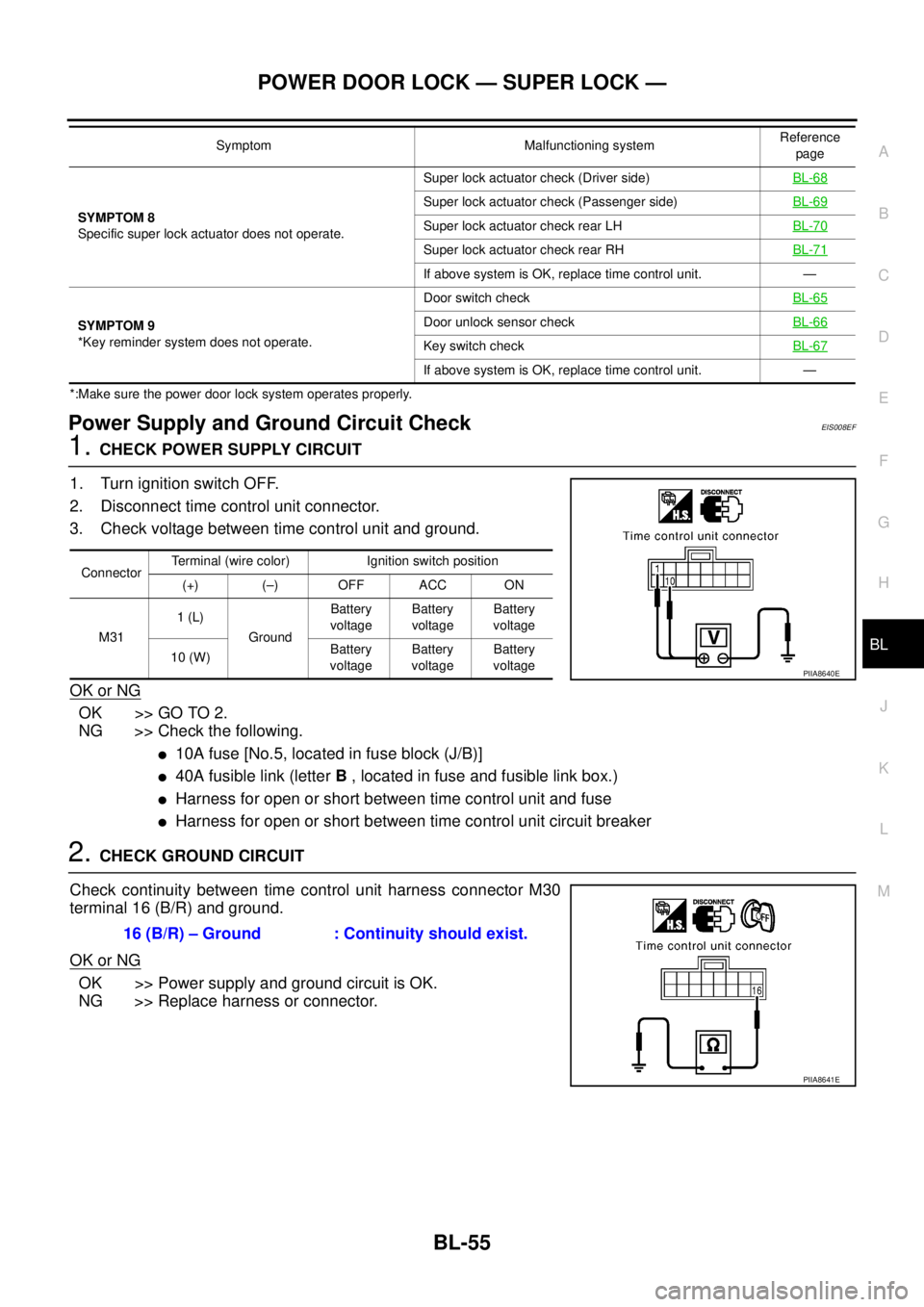
Power Supply and Ground Circuit CheckEIS008EF
1. CHECK POWER SUPPLY CIRCUIT
1. Turn ignition switch OFF.
2. Disconnect time control unit connector.
3. Check voltage between time control unit and ground.
OK or NG
OK >> GO TO 2.
NG >> Check the following.
�10A fuse [No.5, located in fuse block (J/B)]
�40A fusible link (letter B , located in fuse and fusible link box.)
�Harness for open or short between time control unit and fuse
�Harness for open or short between time control unit circuit breaker
2. CHECK GROUND CIRCUIT
Check continuity between time control unit harness connector M30
terminal 16 (B/R) and ground.
OK or NG
OK >> Power supply and ground circuit is OK.
NG >> Replace harness or connector.
SYMPTOM 8
Specific super lock actuator does not operate.Super lock actuator check (Driver side)BL-68
Super lock actuator check (Passenger side)BL-69
Super lock actuator check rear LHBL-70
Super lock actuator check rear RHBL-71
If above system is OK, replace time control unit. —
SYMPTOM 9
*Key reminder system does not operate.Door switch checkBL-65
Door unlock sensor checkBL-66
Key switch checkBL-67
If above system is OK, replace time control unit. — Symptom Malfunctioning systemReference
page
ConnectorTerminal (wire color) Ignition switch position
(+) (–) OFF ACC ON
M311 (L)
GroundBattery
voltageBattery
voltageBattery
voltage
10 (W)Battery
voltageBattery
voltageBattery
voltage
PIIA8640E
16 (B/R) – Ground : Continuity should exist.
PIIA8641E