Page 3638 of 4555
BL-56
POWER DOOR LOCK — SUPER LOCK —
Door Lock/Unlock Switch CheckEIS008EG
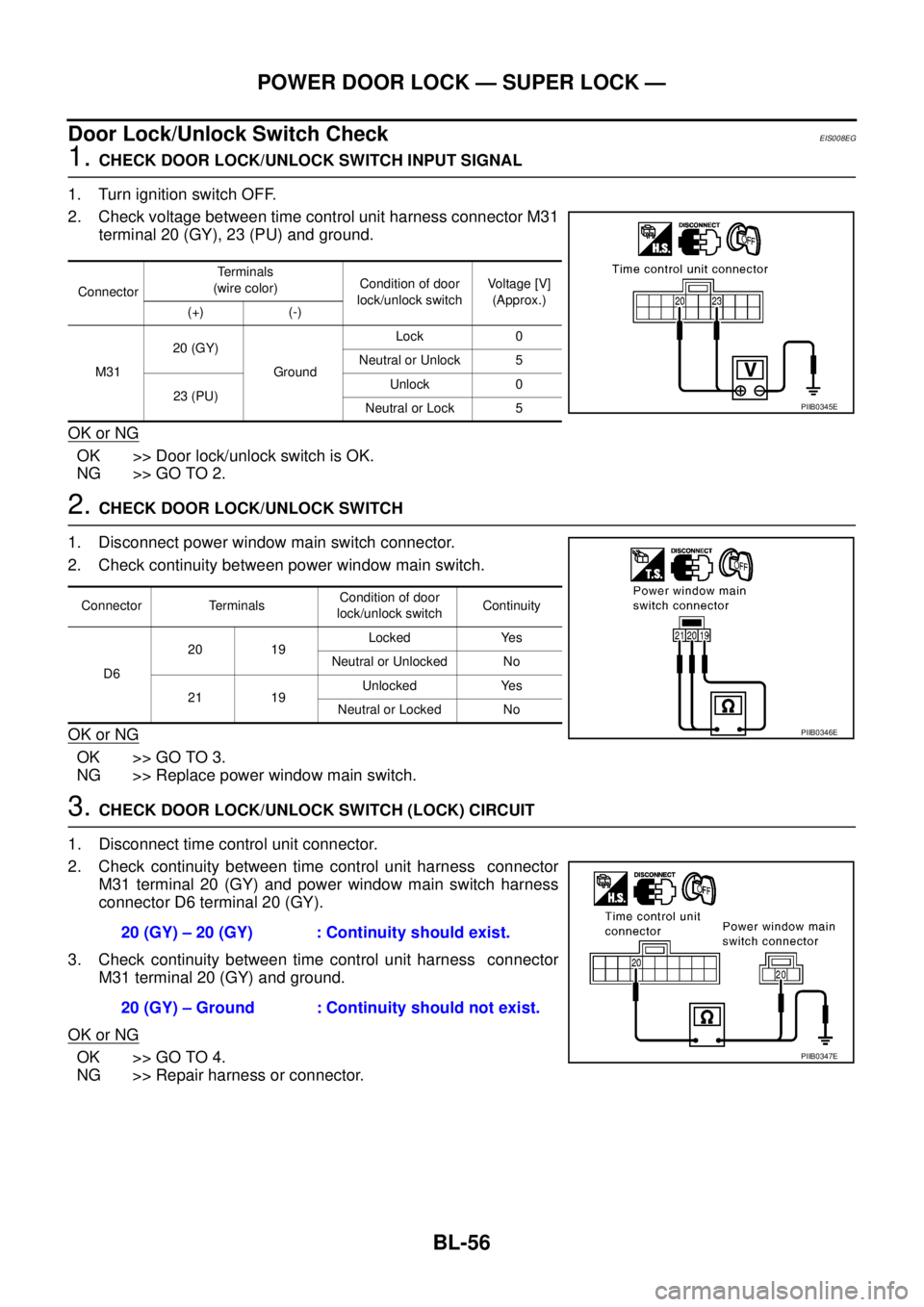
1. CHECK DOOR LOCK/UNLOCK SWITCH INPUT SIGNAL
1. Turn ignition switch OFF.
2. Check voltage between time control unit harness connector M31
terminal 20 (GY), 23 (PU) and ground.
OK or NG
OK >> Door lock/unlock switch is OK.
NG >> GO TO 2.
2. CHECK DOOR LOCK/UNLOCK SWITCH
1. Disconnect power window main switch connector.
2. Check continuity between power window main switch.
OK or NG
OK >> GO TO 3.
NG >> Replace power window main switch.
3. CHECK DOOR LOCK/UNLOCK SWITCH (LOCK) CIRCUIT
1. Disconnect time control unit connector.
2. Check continuity between time control unit harness connector
M31 terminal 20 (GY) and power window main switch harness
connector D6 terminal 20 (GY).
3. Check continuity between time control unit harness connector
M31 terminal 20 (GY) and ground.
OK or NG
OK >> GO TO 4.
NG >> Repair harness or connector.
ConnectorTerminals
(wire color)Condition of door
lock/unlock switchVoltage [V]
(Approx.)
(+) (-)
M3120 (GY)
GroundLock 0
Neutral or Unlock 5
23 (PU)Unlock 0
Neutral or Lock 5
PIIB0345E
Connector TerminalsCondition of door
lock/unlock switchContinuity
D620 19Locked Yes
Neutral or Unlocked No
21 19Unlocked Yes
Neutral or Locked No
PIIB0346E
20 (GY) – 20 (GY) : Continuity should exist.
20 (GY) – Ground : Continuity should not exist.
PIIB0347E
Page 3639 of 4555
POWER DOOR LOCK — SUPER LOCK —
BL-57
C
D
E
F
G
H
J
K
L
MA
B
BL
4. CHECK DOOR LOCK/UNLOCK SWITCH (UNLOCK) CIRCUIT
1. Check continuity between time control unit harness connector
M31 terminal 23 (PU) and power window main switch harness
connector D6 terminal 21 (PU).
2. Check continuity between time control unit harness connector
M31 terminal 23 (PU) and ground.
OK or NG
OK >> GO TO 5.
NG >> Repair harness or connector.
5. CHECK DOOR LOCK/UNLOCK SWITCH GROUND CIRCUIT
1. Check continuity between power window main switch harness
connector D6 terminal 19 (B) and ground.
OK or NG
OK >> Replace power window main switch.
NG >> Repair harness or connector.23 (PU) – 21 (PU) : Continuity should exist.
23 (PU) – Ground : Continuity should not exist.
PIIB0348E
19 (B) – Ground : Continuity should exist.
PIIB0349E
Page 3640 of 4555
BL-58
POWER DOOR LOCK — SUPER LOCK —
Door Key Cylinder Switch CheckEIS008EH
1. CHECK DOOR KEY CYLINDER SWITCH INPUT SIGNAL
Check voltage between time control unit and ground.
OK or NG
OK >> Door key cylinder switch is OK.
NG >> GO TO 2.
2. CHECK DOOR KEY CYLINDER SWITCH
1. Turn ignition switch OFF.
2. Disconnect door key cylinder switch connector.
3. Check continuity between door key cylinder switch.
OK or NG
OK >> GO TO 3.
NG >> Replace door key cylinder switch.
ConnectorTerminals (wire color)
Condition of door key
cylinder switchVoltage [V]
(Approx.)
(+) (–)
M3124 (LG/R)
GroundLocked 0
Neutral or Unlocked 5
25 (GY/L)Unlocked 0
Neutral or Locked 5
PIIA3643E
Connector TerminalsCondition of door key
cylinder switchContinuity
D812Neutral No
Lock Yes
23Neutral No
Unlock Yes
PIIB0350E
Page 3641 of 4555
POWER DOOR LOCK — SUPER LOCK —
BL-59
C
D
E
F
G
H
J
K
L
MA
B
BL
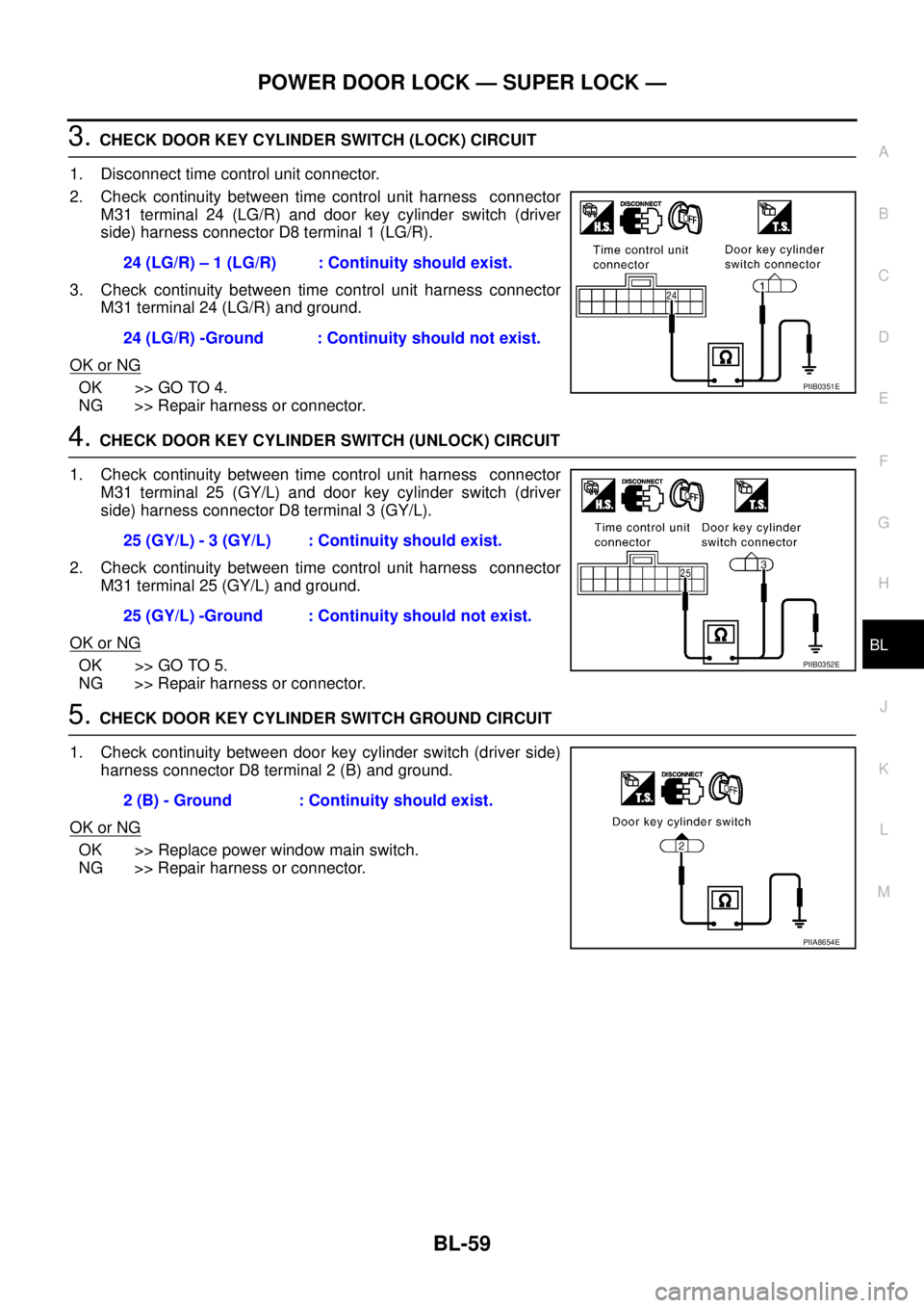
3. CHECK DOOR KEY CYLINDER SWITCH (LOCK) CIRCUIT
1. Disconnect time control unit connector.
2. Check continuity between time control unit harness connector
M31 terminal 24 (LG/R) and door key cylinder switch (driver
side) harness connector D8 terminal 1 (LG/R).
3. Check continuity between time control unit harness connector
M31 terminal 24 (LG/R) and ground.
OK or NG
OK >> GO TO 4.
NG >> Repair harness or connector.
4. CHECK DOOR KEY CYLINDER SWITCH (UNLOCK) CIRCUIT
1. Check continuity between time control unit harness connector
M31 terminal 25 (GY/L) and door key cylinder switch (driver
side) harness connector D8 terminal 3 (GY/L).
2. Check continuity between time control unit harness connector
M31 terminal 25 (GY/L) and ground.
OK or NG
OK >> GO TO 5.
NG >> Repair harness or connector.
5. CHECK DOOR KEY CYLINDER SWITCH GROUND CIRCUIT
1. Check continuity between door key cylinder switch (driver side)
harness connector D8 terminal 2 (B) and ground.
OK or NG
OK >> Replace power window main switch.
NG >> Repair harness or connector.24 (LG/R) – 1 (LG/R) : Continuity should exist.
24 (LG/R) -Ground : Continuity should not exist.
PIIB0351E
25 (GY/L) - 3 (GY/L) : Continuity should exist.
25 (GY/L) -Ground : Continuity should not exist.
PIIB0352E
2 (B) - Ground : Continuity should exist.
PIIA8654E
Page 3642 of 4555
BL-60
POWER DOOR LOCK — SUPER LOCK —
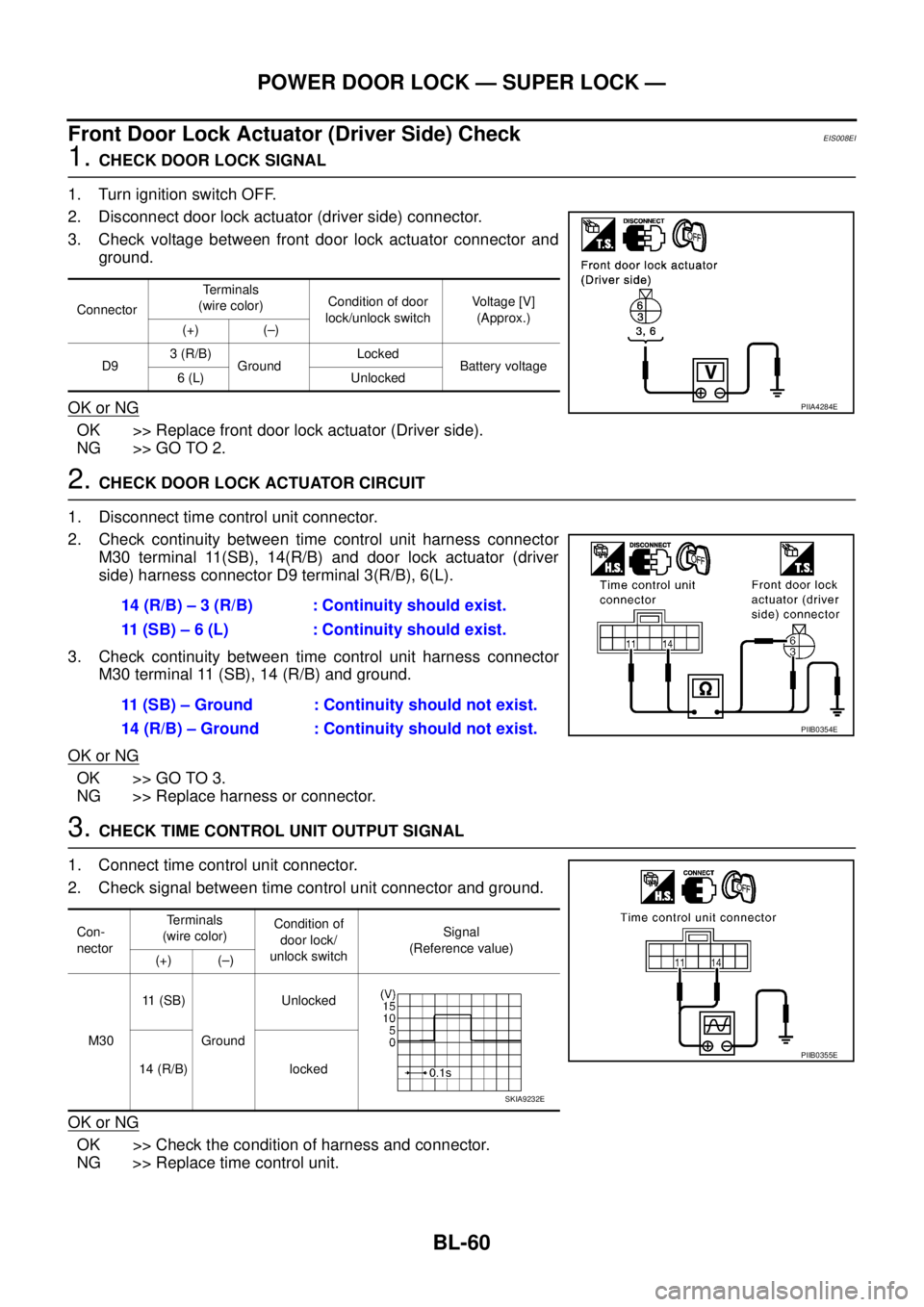
Front Door Lock Actuator (Driver Side) CheckEIS008EI
1. CHECK DOOR LOCK SIGNAL
1. Turn ignition switch OFF.
2. Disconnect door lock actuator (driver side) connector.
3. Check voltage between front door lock actuator connector and
ground.
OK or NG
OK >> Replace front door lock actuator (Driver side).
NG >> GO TO 2.
2. CHECK DOOR LOCK ACTUATOR CIRCUIT
1. Disconnect time control unit connector.
2. Check continuity between time control unit harness connector
M30 terminal 11(SB), 14(R/B) and door lock actuator (driver
side) harness connector D9 terminal 3(R/B), 6(L).
3. Check continuity between time control unit harness connector
M30 terminal 11 (SB), 14 (R/B) and ground.
OK or NG
OK >> GO TO 3.
NG >> Replace harness or connector.
3. CHECK TIME CONTROL UNIT OUTPUT SIGNAL
1. Connect time control unit connector.
2. Check signal between time control unit connector and ground.
OK or NG
OK >> Check the condition of harness and connector.
NG >> Replace time control unit.
ConnectorTerminals
(wire color)Condition of door
lock/unlock switchVoltage [V]
(Approx.)
(+) (–)
D93 (R/B)
GroundLocked
Battery voltage
6 (L) Unlocked
PIIA4284E
14 (R/B) – 3 (R/B) : Continuity should exist.
11 (SB) – 6 (L) : Continuity should exist.
11 (SB) – Ground : Continuity should not exist.
14 (R/B) – Ground : Continuity should not exist.
PIIB0354E
Con-
nectorTerminals
(wire color)Condition of
door lock/
unlock switchSignal
(Reference value)
(+) (–)
M3011 (SB)
GroundUnlocked
14 (R/B) locked
PIIB0355E
SKIA9232E
Page 3643 of 4555
POWER DOOR LOCK — SUPER LOCK —
BL-61
C
D
E
F
G
H
J
K
L
MA
B
BL
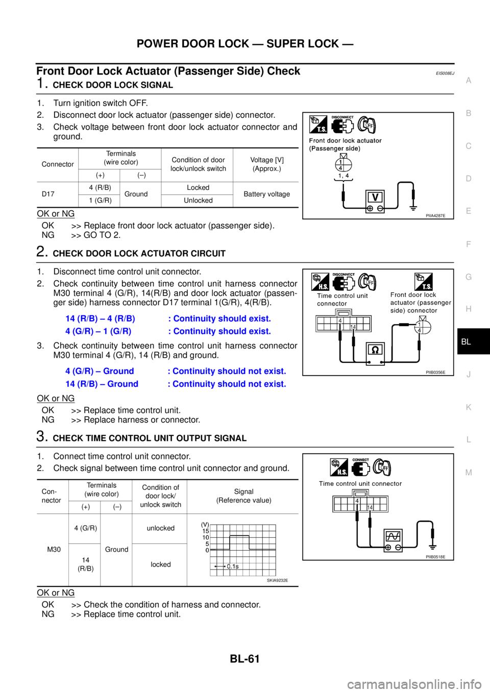
Front Door Lock Actuator (Passenger Side) CheckEIS008EJ
1. CHECK DOOR LOCK SIGNAL
1. Turn ignition switch OFF.
2. Disconnect door lock actuator (passenger side) connector.
3. Check voltage between front door lock actuator connector and
ground.
OK or NG
OK >> Replace front door lock actuator (passenger side).
NG >> GO TO 2.
2. CHECK DOOR LOCK ACTUATOR CIRCUIT
1. Disconnect time control unit connector.
2. Check continuity between time control unit harness connector
M30 terminal 4 (G/R), 14(R/B) and door lock actuator (passen-
ger side) harness connector D17 terminal 1(G/R), 4(R/B).
3. Check continuity between time control unit harness connector
M30 terminal 4 (G/R), 14 (R/B) and ground.
OK or NG
OK >> Replace time control unit.
NG >> Replace harness or connector.
3. CHECK TIME CONTROL UNIT OUTPUT SIGNAL
1. Connect time control unit connector.
2. Check signal between time control unit connector and ground.
OK or NG
OK >> Check the condition of harness and connector.
NG >> Replace time control unit.
ConnectorTerminals
(wire color)Condition of door
lock/unlock switchVoltage [V]
(Approx.)
(+) (–)
D174 (R/B)
GroundLocked
Battery voltage
1 (G/R) Unlocked
PIIA4287E
14 (R/B) – 4 (R/B) : Continuity should exist.
4 (G/R) – 1 (G/R) : Continuity should exist.
4 (G/R) – Ground : Continuity should not exist.
14 (R/B) – Ground : Continuity should not exist.
PIIB0356E
Con-
nectorTerminals
(wire color)Condition of
door lock/
unlock switchSignal
(Reference value)
(+) (–)
M304 (G/R)
Groundunlocked
14
(R/B)locked
PIIB0518E
SKIA9232E
Page 3644 of 4555
BL-62
POWER DOOR LOCK — SUPER LOCK —
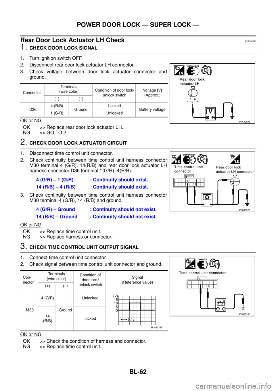
Rear Door Lock Actuator LH CheckEIS008EK
1. CHECK DOOR LOCK SIGNAL
1. Turn ignition switch OFF.
2. Disconnect rear door lock actuator LH connector.
3. Check voltage between door lock actuator connector and
ground.
OK or NG
OK >> Replace rear door lock actuator LH.
NG >> GO TO 2.
2. CHECK DOOR LOCK ACTUATOR CIRCUIT
1. Disconnect time control unit connector.
2. Check continuity between time control unit harness connector
M30 terminal 4 (G/R), 14(R/B) and rear door lock actuator LH
harness connector D36 terminal 1(G/R), 4(R/B).
3. Check continuity between time control unit harness connector
M30 terminal 4 (G/R), 14 (R/B) and ground.
OK or NG
OK >> Replace time control unit.
NG >> Replace harness or connector.
3. CHECK TIME CONTROL UNIT OUTPUT SIGNAL
1. Connect time control unit connector.
2. Check signal between time control unit connector and ground.
OK or NG
OK >> Check the condition of harness and connector.
NG >> Replace time control unit.
ConnectorTerminals
(wire color)Condition of door lock/
unlock switchVoltage [V]
(Approx.)
(+) (–)
D364 (R/B)
GroundLocked
Battery voltage
1 (G/R) Unlocked
PIIA4289E
4 (G/R) – 1 (G/R) : Continuity should exist.
14 (R/B) – 4 (R/B) : Continuity should exist.
4 (G/R) – Ground : Continuity should not exist.
14 (R/B) – Ground : Continuity should not exist.
PIIB0357E
Con-
nectorTerminals
(wire color)Condition of
door lock/
unlock switchSignal
(Reference value)
(+) (–)
M304 (G/R)
GroundUnlocked
14
(R/B)locked
PIIB0518E
SKIA9232E
Page 3645 of 4555
POWER DOOR LOCK — SUPER LOCK —
BL-63
C
D
E
F
G
H
J
K
L
MA
B
BL
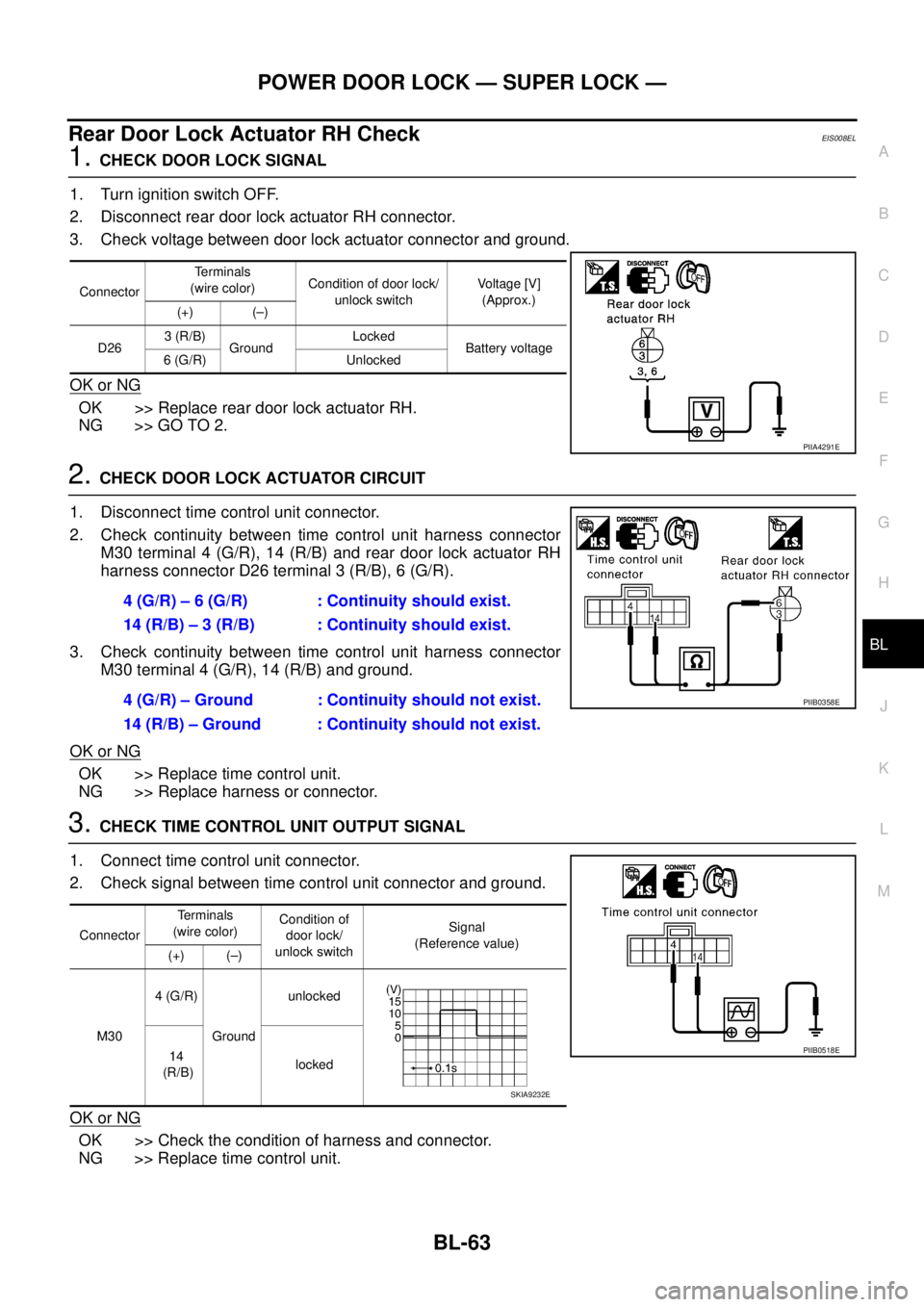
Rear Door Lock Actuator RH CheckEIS008EL
1. CHECK DOOR LOCK SIGNAL
1. Turn ignition switch OFF.
2. Disconnect rear door lock actuator RH connector.
3. Check voltage between door lock actuator connector and ground.
OK or NG
OK >> Replace rear door lock actuator RH.
NG >> GO TO 2.
2. CHECK DOOR LOCK ACTUATOR CIRCUIT
1. Disconnect time control unit connector.
2. Check continuity between time control unit harness connector
M30 terminal 4 (G/R), 14 (R/B) and rear door lock actuator RH
harness connector D26 terminal 3 (R/B), 6 (G/R).
3. Check continuity between time control unit harness connector
M30 terminal 4 (G/R), 14 (R/B) and ground.
OK or NG
OK >> Replace time control unit.
NG >> Replace harness or connector.
3. CHECK TIME CONTROL UNIT OUTPUT SIGNAL
1. Connect time control unit connector.
2. Check signal between time control unit connector and ground.
OK or NG
OK >> Check the condition of harness and connector.
NG >> Replace time control unit.
ConnectorTerminals
(wire color)Condition of door lock/
unlock switchVoltage [V]
(Approx.)
(+) (–)
D263 (R/B)
GroundLocked
Battery voltage
6 (G/R) Unlocked
PIIA4291E
4 (G/R) – 6 (G/R) : Continuity should exist.
14 (R/B) – 3 (R/B) : Continuity should exist.
4 (G/R) – Ground : Continuity should not exist.
14 (R/B) – Ground : Continuity should not exist.
PIIB0358E
ConnectorTerminals
(wire color)Condition of
door lock/
unlock switchSignal
(Reference value)
(+) (–)
M304 (G/R)
Groundunlocked
14
(R/B)locked
PIIB0518E
SKIA9232E