Page 3669 of 4555
MULTI-REMOTE CONTROL SYSTEM
BL-87
C
D
E
F
G
H
J
K
L
MA
B
BL
3. CHECK HAZARD LAMP LH CIRCUIT
1. Turn ignition switch OFF.
2. Disconnect multi-remote control unit, side turn signal lamp LH and front and rear combination lamp LH
connector.
3. Check continuity between multi-remote control unit connector
M33 terminal 8 (G/B) and front turn signal lamp LH connector
E47 terminal 1 (G/B).
4. Check continuity between multi-remote control unit connector
M33 terminal 8 (G/B) and rear combination lamp LH connector
B28 terminal 2 (G/B).
5. Check continuity between multi-remote control unit connector
M33 terminal 8 (G/B) and side turn signal lamp LH connector
E48 terminal 1 (G/B).
OK or NG
OK >> GO TO 4.
NG >> Repair harness or connector.8 (G/B) – 1 (G/B) : Continuity should exist.
PIIB0373E
8 (G/B) – 2 (G/B) : Continuity should exist.
PIIB0374E
8 (G/B) – 1 (G/B) : Continuity should exist.
PIIB0375E
Page 3670 of 4555
BL-88
MULTI-REMOTE CONTROL SYSTEM
4. CHECK HAZARD LAMP RH CIRCUIT
1. Turn ignition switch OFF.
2. Disconnect side turn signal lamp RH and front and rear combination lamp RH connector.
3. Check continuity between multi-remote control unit connector
M33 terminal 3 (G/Y) and front turn signal lamp RH connector
E25 terminal 1 (G/Y).
4. Check continuity between multi-remote control unit connector
M33 terminal 3 (G/Y) and rear combination lamp RH connector
B24 terminal 2 (G/Y).
5. Check continuity between multi-remote control unit connector
M33 terminal 3 (G/Y) and side turn signal lamp RH connector
E20 terminal 1 (G/Y).
OK or NG
OK >> Hazard lamp circuit is OK.
NG >> Repair harness or connector.3 (G/Y) – 1 (G/Y) : Continuity should exist.
PIIB0376E
3 (G/Y) – 2 (G/Y) : Continuity should exist.
PIIB0377E
3 (G/Y) – 1 (G/Y) : Continuity should exist.
PIIB0378E
Page 3672 of 4555
BL-90
MULTI-REMOTE CONTROL SYSTEM
Remote Controller Battery ReplacementEIS008EZ
1. Remove screw on the rear of keyfob.
2. Place the key with the lower case facing up. Insert a screwdriver
wrapped with tape into “A” of the lower case and separate the
lower case from the upper case.
3. When replacing the circuit board assembly, remove circuit board
assembly from the upper case.
(Circuit board assembly: Switch rubber + Board surface)
CAUTION:
Be careful not to touch the printed circuits directly.
4. When replacing the battery
Remove battery from the lower case and replace it.
CAUTION:
When replacing battery, be sure to keep the electrode con-
tact area from dirt, grease or other foreign materials.
5. After replacement, fit the lower and upper cases together,
tighten with the screw.
CAUTION:
After replacing the battery, be sure to check that door lock-
ing operates normally using the keyfob. Battery
replacement: Coin-type lithium battery (CR2016)
PIIA9409E
Page 3682 of 4555
BL-100
BACK DOOR
Back Door AssemblyEIS000LG
REMOVAL AND INSTALLATION
Removal
1. Disconnect connectors in the back door and encamp the harness. Pull the harness out of the back door.
2. Support the back door lock with a proper material to prevent it from falling and remove back door stay (gas
stay).
3. Remove hinge mount nuts on the back door and remove back door assembly.
Installation
Install in the reverse order of removal.
INSPECTION
1. Check hinges for the following items
�Abnormal noise or door closing and opening effort
�Component wear or damage
2. Apply Body Grease to the rotating part of the hinge.
Removal and Installation of Back Door HandleEIS0015D
REMOVAL
1. Remove back door trim. Refer to EI-34, "BACK DOOR TRIM" .
SIIA0085E
PIIA3747E
Page 3699 of 4555

NATS (NISSAN ANTI-THEFT SYSTEM)
BL-117
C
D
E
F
G
H
J
K
L
MA
B
BL
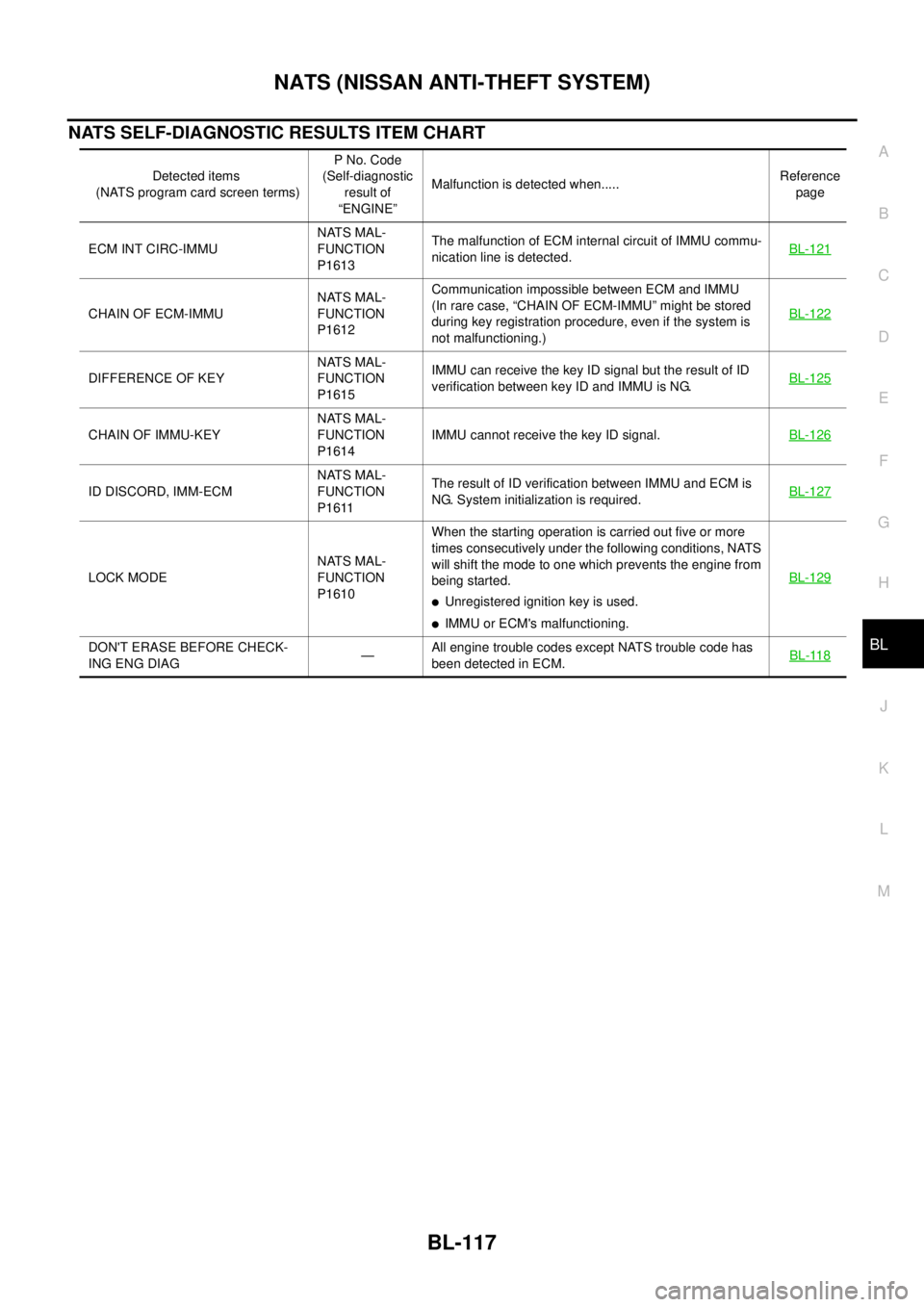
NATS SELF-DIAGNOSTIC RESULTS ITEM CHART
Detected items
(NATS program card screen terms)P No. Code
(Self-diagnostic
result of
“ENGINE”Malfunction is detected when.....Reference
page
ECM INT CIRC-IMMUNATS MAL-
FUNCTION
P1613The malfunction of ECM internal circuit of IMMU commu-
nication line is detected.BL-121
CHAIN OF ECM-IMMUNATS MAL-
FUNCTION
P1612Communication impossible between ECM and IMMU
(In rare case, “CHAIN OF ECM-IMMU” might be stored
during key registration procedure, even if the system is
not malfunctioning.)BL-122
DIFFERENCE OF KEYNATS MAL-
FUNCTION
P1615IMMU can receive the key ID signal but the result of ID
verification between key ID and IMMU is NG.BL-125
CHAIN OF IMMU-KEYNATS MAL-
FUNCTION
P1614IMMU cannot receive the key ID signal.BL-126
ID DISCORD, IMM-ECMNATS MAL-
FUNCTION
P1611The result of ID verification between IMMU and ECM is
NG. System initialization is required.BL-127
LOCK MODENATS MAL-
FUNCTION
P1610When the starting operation is carried out five or more
times consecutively under the following conditions, NATS
will shift the mode to one which prevents the engine from
being started.
�Unregistered ignition key is used.
�IMMU or ECM's malfunctioning.BL-129
DON'T ERASE BEFORE CHECK-
ING ENG DIAG—All engine trouble codes except NATS trouble code has
been detected in ECM.BL-118
Page 3702 of 4555

BL-120
NATS (NISSAN ANTI-THEFT SYSTEM)
*: When NATS detects trouble, the security indicator lights up while ignition key is in the “ON” position.
*: When the vehicle is equipped with a dongle unit (RHD models), the security indicator blinks 6 times just after the ignition switch is
turned to ON. Then the security indicator lights up while the ignition key is in the “ON” position.
�Security indicator
lighting up*
�Engine cannot be
startedLOCK MODEPROCEDURE 7
(BL-129 )LOCK MODEWhen the starting opera-
tion is carried out five or
more times consecu-
tively under the follow-
ing conditions, NATS will
shift the mode to one
which prevents the
engine from being
started.
�Unregistered ignition
key is used.
�IMMU or ECM's mal-
functioning.
�MIL staying ON
�Security indicator
lighting up*DON'T ERASE
BEFORE CHECKING
ENG DIAGWORK FLOW
(BL-118 )Engine trouble data and
NATS trouble data have
been detected in ECM— SYMPTOMDisplayed “SELF-DIAG
RESULTS” on CON-
SULT-II screen.DIAGNOSTIC PROCE-
DURE
(Reference page)SYSTEM
(Malfunctioning part or
mode)REFERENCE PART NO.
OF ILLUSTRATION ON
SYSTEM DIAGRAM
Page 3704 of 4555

BL-122
NATS (NISSAN ANTI-THEFT SYSTEM)
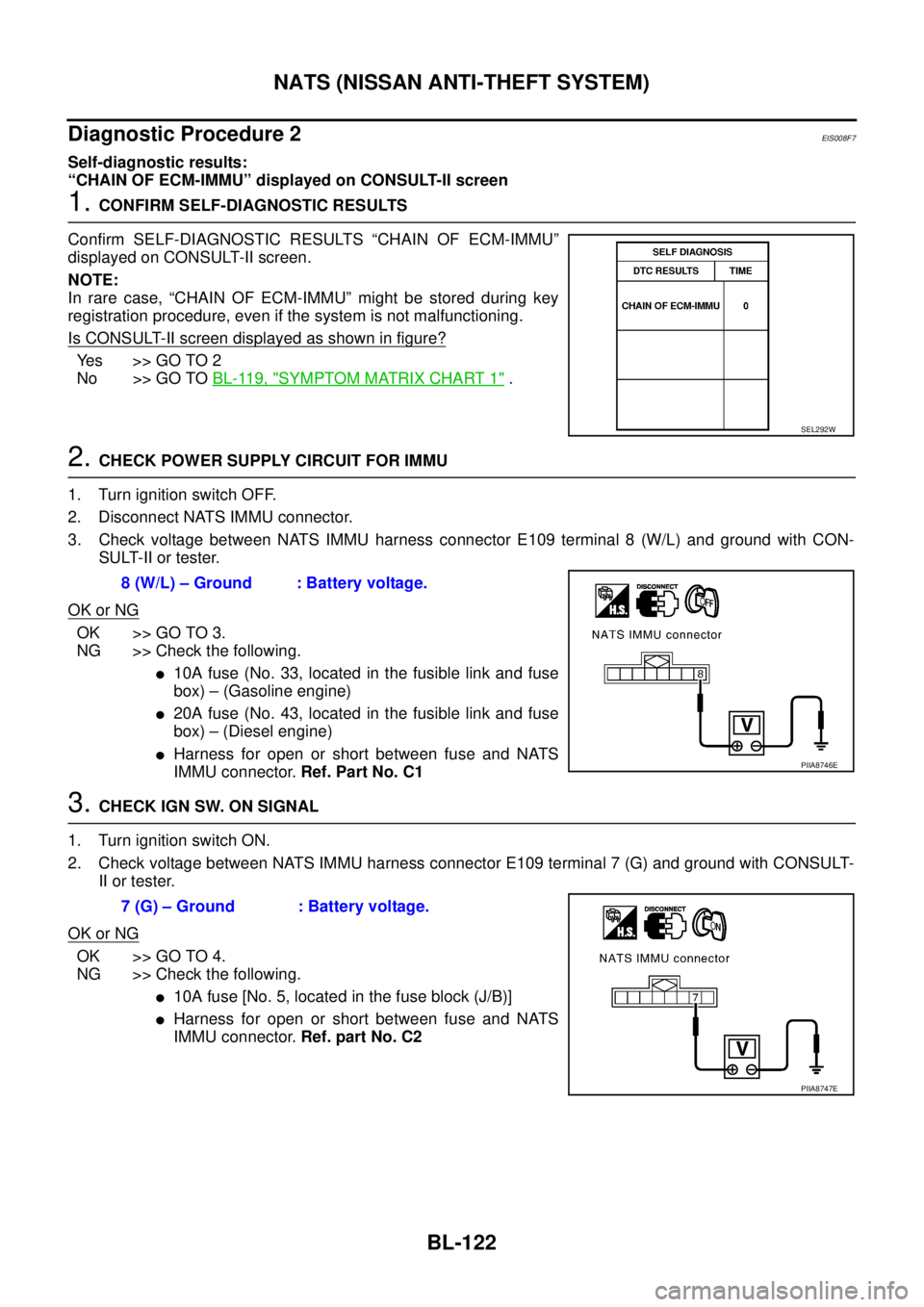
Diagnostic Procedure 2EIS008F7
Self-diagnostic results:
“CHAIN OF ECM-IMMU” displayed on CONSULT-II screen
1. CONFIRM SELF-DIAGNOSTIC RESULTS
Confirm SELF-DIAGNOSTIC RESULTS “CHAIN OF ECM-IMMU”
displayed on CONSULT-II screen.
NOTE:
In rare case, “CHAIN OF ECM-IMMU” might be stored during key
registration procedure, even if the system is not malfunctioning.
Is CONSULT-II screen displayed as shown in figure?
Yes >> GO TO 2
No >> GO TO BL-119, "
SYMPTOM MATRIX CHART 1" .
2. CHECK POWER SUPPLY CIRCUIT FOR IMMU
1. Turn ignition switch OFF.
2. Disconnect NATS IMMU connector.
3. Check voltage between NATS IMMU harness connector E109 terminal 8 (W/L) and ground with CON-
SULT-II or tester.
OK or NG
OK >> GO TO 3.
NG >> Check the following.
�10A fuse (No. 33, located in the fusible link and fuse
box) – (Gasoline engine)
�20A fuse (No. 43, located in the fusible link and fuse
box) – (Diesel engine)
�Harness for open or short between fuse and NATS
IMMU connector. Ref. Part No. C1
3. CHECK IGN SW. ON SIGNAL
1. Turn ignition switch ON.
2. Check voltage between NATS IMMU harness connector E109 terminal 7 (G) and ground with CONSULT-
II or tester.
OK or NG
OK >> GO TO 4.
NG >> Check the following.
�10A fuse [No. 5, located in the fuse block (J/B)]
�Harness for open or short between fuse and NATS
IMMU connector. Ref. part No. C2
SEL292W
8 (W/L) – Ground : Battery voltage.
PIIA8746E
7 (G) – Ground : Battery voltage.
PIIA8747E
Page 3705 of 4555

NATS (NISSAN ANTI-THEFT SYSTEM)
BL-123
C
D
E
F
G
H
J
K
L
MA
B
BL
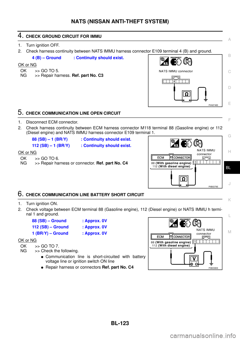
4. CHECK GROUND CIRCUIT FOR IMMU
1. Turn ignition OFF.
2. Check harness continuity between NATS IMMU harness connector E109 terminal 4 (B) and ground.
OK or NG
OK >> GO TO 5.
NG >> Repair harness. Ref. part No. C3
5. CHECK COMMUNICATION LINE OPEN CIRCUIT
1. Disconnect ECM connector.
2. Check harness continuity between ECM harness connector M118 terminal 88 (Gasoline engine) or 112
(Diesel engine) and NATS IMMU harness connector E109 terminal 1.
OK or NG
OK >> GO TO 6.
NG >> Repair harness or connector. Ref. part No. C4
6. CHECK COMMUNICATION LINE BATTERY SHORT CIRCUIT
1. Turn ignition ON.
2. Check voltage between ECM terminal 88 (Gasoline engine), 112 (Diesel engine) or NATS IMMU h termi-
nal 1 and ground.
OK or NG
OK >> GO TO 7.
NG >> Check the following.
�Communication line is short-circuited with battery
voltage line or ignition switch ON line
�Repair harness or connectors Ref. part No. C4 4 (B) – Ground : Continuity should exist.
PIIA8748E
88 (SB) – 1 (BR/Y) : Continuity should exist.
112 (SB) – 1 (BR/Y) : Continuity should exist.
PIIB0379E
88 (SB) – Ground : Approx. 0V
112 (SB) – Ground : Approx. 0V
1 (BR/Y) – Ground : Approx. 0V
PIIB0380E