Page 3750 of 4555
GW-36
REAR WINDOW DEFOGGER
Rear Window Defogger Indicator Lamp Check 2EIS008AS
1. CHECK REAR WINDOW DEFOGGER SIGNAL
1. Turn both ignition switch and rear window defogger switch ON.
2.(Without auto A/C)
Check voltage between rear window defogger switch connector
M50 terminal 3 and ground.
(With auto A/C)
Check voltage between A/C auto amp, connector M53 terminal
23 and ground.
OK or NG
OK >> GO TO 3.
NG >> GO TO 2.3 (B/W) - Ground : Battery voltage
PIIA9565E
23 (B/W) - Ground : Battery voltage
PIIA9566E
Page 3751 of 4555

REAR WINDOW DEFOGGER
GW-37
C
D
E
F
G
H
J
K
L
MA
B
GW
2. CHECK HARNESS CONTINUITY
1. Turn ignition switch OFF.
2. Disconnect rear window defogger switch (without auto A/C) or A/C auto amp, (with auto A/C) connector
and rear window defogger relay.
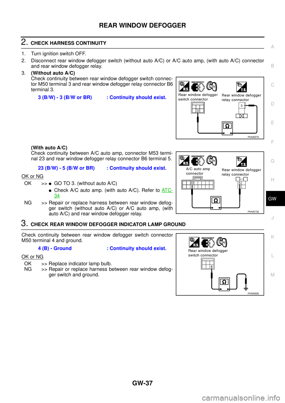
3.(Without auto A/C)
Check continuity between rear window defogger switch connec-
tor M50 terminal 3 and rear window defogger relay connector B6
terminal 3.
(With auto A/C)
Check continuity between A/C auto amp, connector M53 termi-
nal 23 and rear window defogger relay connector B6 terminal 5.
OK or NG
OK >>�GO TO 3. (without auto A/C)
�Check A/C auto amp. (with auto A/C). Refer to AT C -
34
NG >> Repair or replace harness between rear window defog-
ger switch (without auto A/C) or A/C auto amp, (with
auto A/C) and rear window defogger relay.
3. CHECK REAR WINDOW DEFOGGER INDICATOR LAMP GROUND
Check continuity between rear window defogger switch connector
M50 terminal 4 and ground.
OK or NG
OK >> Replace indicator lamp bulb.
NG >> Repair or replace harness between rear window defog-
ger switch and ground. 3 (B/W) - 3 (B/W or BR) : Continuity should exist.
PIIA9567E
23 (B/W) - 5 (B/W or BR) : Continuity should exist.
PIIA9573E
4 (B) - Ground : Continuity should exist.
PIIA9569E
Page 3752 of 4555
GW-38
REAR WINDOW DEFOGGER
Filament CheckEIS008AU
1. When measuring voltage, wrap tin foil around the top of the neg-
ative probe.Then press the foil against the wire with your finder.
2. Attach probe circuit tester (in Volt range) to middle portion of
each filament.
3. If a filament is burned out, circuit tester registers 0 or battery
voltage.
4. To locate burned out point, move probe to left and right along fil-
ament.Test needle will swing abruptly when probe passes the
point.
Filament RepairEIS008AV
REPAIR EQUIPMENT
�Conductive silver composition (Dupont NO.4817 or equivalent)
�Ruler 30 cm(11.8in) long
�Drawing pen
�Heat gun
�Alcohol
�Cloth
SEL122R
SEL263
SEL265
Page 3753 of 4555

REAR WINDOW DEFOGGER
GW-39
C
D
E
F
G
H
J
K
L
MA
B
GW
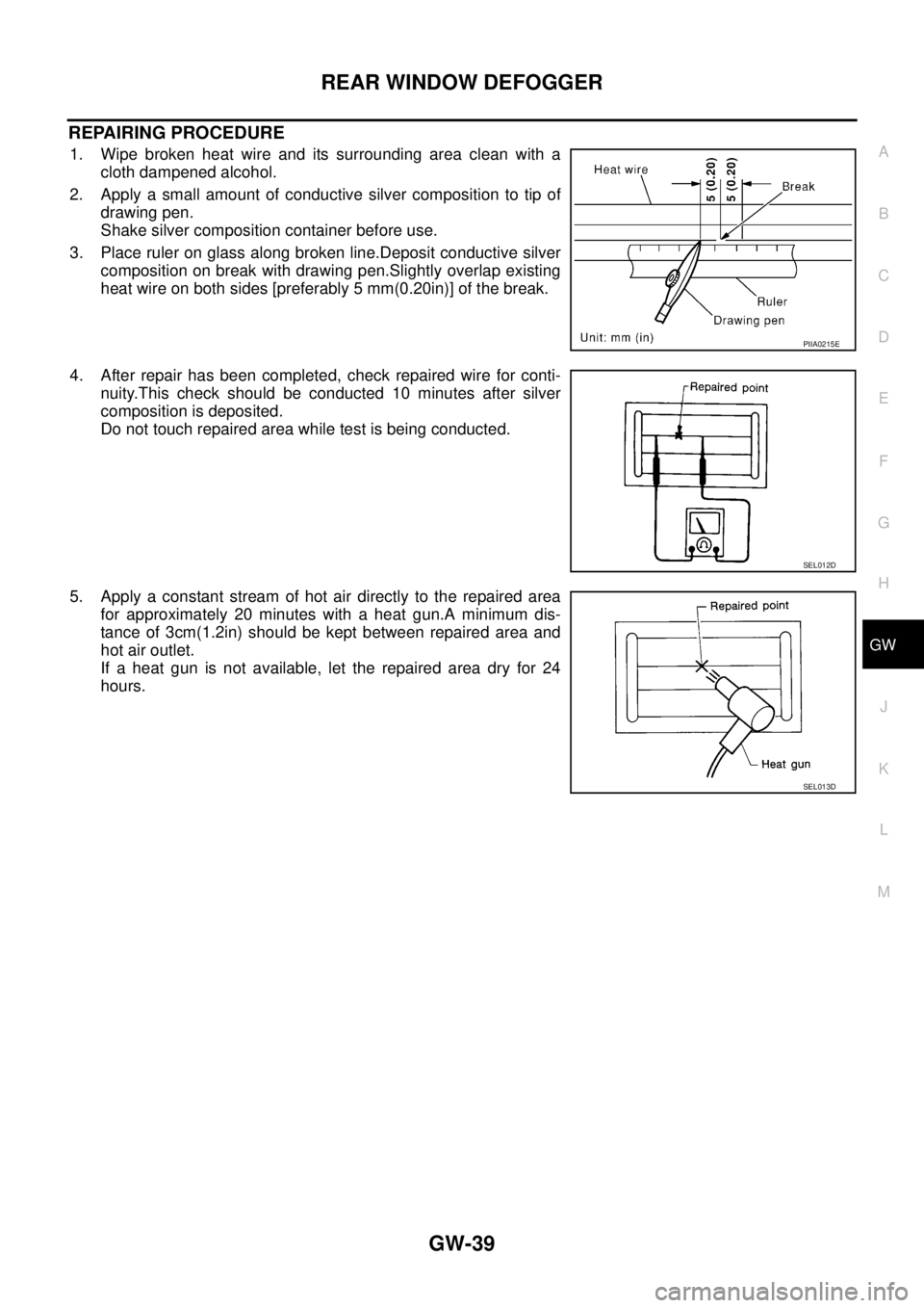
REPAIRING PROCEDURE
1. Wipe broken heat wire and its surrounding area clean with a
cloth dampened alcohol.
2. Apply a small amount of conductive silver composition to tip of
drawing pen.
Shake silver composition container before use.
3. Place ruler on glass along broken line.Deposit conductive silver
composition on break with drawing pen.Slightly overlap existing
heat wire on both sides [preferably 5 mm(0.20in)] of the break.
4. After repair has been completed, check repaired wire for conti-
nuity.This check should be conducted 10 minutes after silver
composition is deposited.
Do not touch repaired area while test is being conducted.
5. Apply a constant stream of hot air directly to the repaired area
for approximately 20 minutes with a heat gun.A minimum dis-
tance of 3cm(1.2in) should be kept between repaired area and
hot air outlet.
If a heat gun is not available, let the repaired area dry for 24
hours.
PIIA0215E
SEL012D
SEL013D
Page 3772 of 4555

GW-58
POWER WINDOW SYSTEM
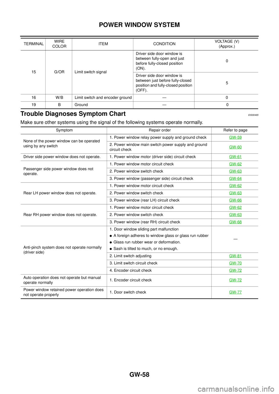
Trouble Diagnoses Symptom ChartEIS00465
Make sure other systems using the signal of the following systems operate normally.
15 G/OR Limit switch signalDriver side door window is
between fully-open and just
before fully-closed position
(ON).0
Driver side door window is
between just before fully-closed
position and fully-closed position
(OFF).5
16 W/B Limit switch and encoder ground — 0
19 B Ground — 0 TERMINALWIRE
COLORITEM CONDITIONVOLTAGE (V)
(Approx.)
Symptom Repair order Refer to page
None of the power window can be operated
using by any switch1. Power window relay power supply and ground checkGW-59
2. Power window main switch power supply and ground
circuit checkGW-60
Driver side power window does not operate. 1. Power window motor (driver side) circuit checkGW-61
Passenger side power window does not
operate.1. Power window motor circuit checkGW-622. Power window switch checkGW-63
3. Power window (passenger side) circuit checkGW-64
Rear LH power window does not operate.1. Power window motor circuit checkGW-622. Power window switch checkGW-63
3. Power window (rear LH) circuit checkGW-66
Rear RH power window does not operate.1. Power window motor circuit checkGW-622. Power window switch checkGW-63
3. Power window (rear RH) circuit checkGW-68
Anti-pinch system does not operate normally
(driver side)1. Door window sliding part malfunction
�A foreign adheres to window glass or glass run rubber
�Glass run rubber wear or deformation.
�Sash is tilted to much, or no enough.—
2. Limit switch adjustingGW-81
3. Limit switch circuit checkGW-70
4. Encoder circuit checkGW-72
Auto operation does not operate but manual
operate normally1. Encoder circuit checkGW-72
Power window retained power operation does
not operate properly1. Door switch checkGW-77
Page 3773 of 4555
![NISSAN X-TRAIL 2005 Service Repair Manual POWER WINDOW SYSTEM
GW-59
C
D
E
F
G
H
J
K
L
MA
B
GW
Power Window Relay Power Supply and Ground Circuit CheckEIS008BB
1. CHECK FUSE
�Check 10A fuse [No. 5, located in fuse block (J/B)]
�Check 40A fus NISSAN X-TRAIL 2005 Service Repair Manual POWER WINDOW SYSTEM
GW-59
C
D
E
F
G
H
J
K
L
MA
B
GW
Power Window Relay Power Supply and Ground Circuit CheckEIS008BB
1. CHECK FUSE
�Check 10A fuse [No. 5, located in fuse block (J/B)]
�Check 40A fus](/manual-img/5/57403/w960_57403-3772.png)
POWER WINDOW SYSTEM
GW-59
C
D
E
F
G
H
J
K
L
MA
B
GW
Power Window Relay Power Supply and Ground Circuit CheckEIS008BB
1. CHECK FUSE
�Check 10A fuse [No. 5, located in fuse block (J/B)]
�Check 40A fusible link (litter B , located in the fuse and fusible link box.)
NOTE:
Refer to GW-40, "
Component Parts and Harness Connector Location" .
OK or NG
OK >> GO TO 2.
NG >> If fuse is blown out, be sure to eliminate cause of malfunction before installing new fuse. Refer to
PG-2, "
POWER SUPPLY ROUTING" .
2. CHECK POWER WINDOW RELAY POWER SUPPLY
1. Turn ignition switch OFF.
2. Remove power window relay.
3. Turn ignition switch ON.
4. Check voltage between power window relay connector M3 ter-
minal 1, 3 and ground.
OK or NG
OK >> GO TO 3.
NG >> Check power window relay power supply circuit for open
or short.
3. CHECK POWER WINDOW RELAY GROUND
1. Turn ignition switch OFF.
2. Check continuity between power window relay connector M3
terminal 2 and ground.
OK or NG
OK >> GO TO 4.
NG >> Check power window relay ground circuit for open or
short.
4. CHECK POWER WINDOW RELAY
Check continuity between power window relay terminal 3 and 5.
OK or NG
OK >> Check the condition of the harness and the connector.
NG >> Replace power window relay.1 (G) - Ground : Battery voltage
3 (W) - Ground : Battery voltage
PIIA9574E
2 (B) - Ground : Continuity should exist.
PIIA9575E
Terminal Condition Continuity
3512V direct current supply between
terminals 1 and 2Ye s
No current supply No
PIIA2636E
Page 3774 of 4555
GW-60
POWER WINDOW SYSTEM
Power Window Main Switch Power Supply and Ground Circuit CheckEIS008BC
1. CHECK POWER SUPPLY CIRCUIT
1. Turn ignition switch ON.
2. Check voltage between power window main switch connector
D7 terminal 5, 12 (LHD) or 3, 12 (RHD) and ground.
OK or NG
OK >> GO TO 2.
NG >> Repair or replace harness between power window main switch power supply circuit.
2. CHECK POWER WINDOW MAIN SWITCH GROUND CIRCUIT
1. Turn ignition switch OFF.
2. Disconnect power window main switch connector.
3. Check continuity between power window main switch connector
D6 terminal 19 and ground.
OK or NG
OK >> Power window main switch power supply and ground
circuit is OK.
NG >> Repair or replace harness between power window main
switch and ground. (LHD models)
5 (W) - Ground : Battery voltage
12 (W/R) - Ground : Battery voltage
(RHD models)
3 (W) - Ground : Battery voltage
12 (W/R) - Ground : Battery voltage
PIIA9576E
19 (B) - Ground : Continuity should exist.
PIIA9577E
Page 3775 of 4555
POWER WINDOW SYSTEM
GW-61
C
D
E
F
G
H
J
K
L
MA
B
GW
Power Window Motor (Driver side) Circuit CheckEIS008BD
1. CHECK POWER WINDOW MAIN SWITCH SIGNAL
1. Turn ignition switch ON.
2. Driver side switch in power window main switch operated, check voltage between
Power window main switch connector and ground.
(LHD)
(RHD)
OK or NG
OK >> GO TO 2.
NG >> Replace power window main switch.
Connector Terminal (Wire color)
ConditionVoltage (V)
(Approx.)
(+) (-)
D71 (L)
GroundClosing 0
Opening Battery voltage
2 (G/B) Closing Battery voltage
Opening 0
PIIA9578E
ConnectorTerminal (Wire color)
Condition Voltage (V)
(+) (-)
D7 6 (G/B)
GroundClosing Battery voltage
Opening 0
7 (L)Closing 0
Opening Battery voltage
PIIA9579E