Page 3555 of 4555

TROUBLE DIAGNOSIS
SRS-23
C
D
E
F
G
I
J
K
L
MA
B
SRS
NOTE:
�Follow the procedures in numerical order when repairing malfunctioning parts. Confirm whether malfunc-
tion is eliminated using air bag warning lamp or CONSULT-II each time repair is finished. If malfunction is
still observed, proceed to the next step. When malfunction is eliminated, further repair work is not
required.
�Follow the procedure in numerical order when repairing malfunctioning parts, then make the system
check.
�The screen contents are the same as the self-diagnosis results, self-diagnosis results “SELF-DIAG [CUR-
RENT]” and “SELF-DIAG [PAST]”.
SATELLITE SENS LH
[UNIT FAIL]
SATELLITE SENS LH
[COMM FAIL]�LH side air bag (Satellite) sensor 1. Visually check the wiring harness
connection.
2. Replace the harness if it has visible
damage.
3. Replace the LH side air bag (Satel-
lite) sensor.
4. Replace the diagnosis sensor unit.
5. Replace the related harness.
SATELLITE SENS RH
[UNIT FAIL]
SATELLITE SENS RH
[COMM FAIL]
�RH side air bag (Satellite) sensor 1. Visually check the wiring harness
connection.
2. Replace the harness if it has visible
damage.
3. Replace the RH side air bag (Satel-
lite) sensor.
4. Replace the diagnosis sensor unit.
5. Replace the related harness.
PRE-TEN FRONT LH
[OPEN]
�Front LH pre-tensioner circuit is open. 1. Visually check the wiring harness
connections.
2. Replace the harness if it has visible
damage.
3. Replace the front LH seat belt.
(Before disposal, it must be acti-
vated.)
4. Replace the diagnosis sensor unit.
5. Replace the related harness. PRE-TEN FRONT LH
[VB-SHORT]
�Front LH pre-tensioner circuit is shorted to a power supply cir-
cuit.
PRE-TEN FRONT LH
[GND-SHORT]
�Front LH pre-tensioner circuit is shorted to ground.
PRE-TEN FRONT LH
[SHORT]
�Front LH pre-tensioner circuit is shorted between lines.
PRE-TEN FRONT RH
[OPEN]
�Front RH pre-tensioner circuit is open. 1. Visually check the wiring harness
connections.
2. Replace the harness if it has visible
damage.
3. Replace the front RH seat belt.
(Before disposal, it must be acti-
vated.)
4. Replace the diagnosis sensor unit.
5. Replace the related harness. PRE-TEN FRONT RH
[VB-SHORT]
�Front RH pre-tensioner circuit is shorted to a power supply cir-
cuit.
PRE-TEN FRONT RH
[GND-SHORT]
�Front RH pre-tensioner circuit is shorted to ground.
PRE-TEN FRONT RH
[SHORT]
�Front RH pre-tensioner circuit is shorted between lines.
CONTROL UNIT
�Diagnosis sensor unit is malfunctioning. 1. Visually check the wiring harness
connection.
2. Replace the diagnosis sensor unit. Diagnostic item ExplanationRepair order
“Recheck SRS at each replacement”
Page 3556 of 4555
SRS-24
TROUBLE DIAGNOSIS
Trouble Diagnosis without CONSULT-IIEHS000OA
DIAGNOSTIC PROCEDURE 4
CAUTION:
SRS will not enter diagnosis mode if no malfunction is detected in user mode.
1. Turn ignition switch ON.
2. After “AIR BAG” warning lamp lights for 7 seconds, turn ignition switch OFF within 1 second.
3. Wait more than 3 seconds.
4. Repeat the steps 1 to 3 two times.
5. Turn ignition switch ON.
6. Compare the number of flashes to Air Bag Warning Lamp Flash Code.
7. Turn the ignition switch OFF, and disconnect both battery cables.
8. Repair the system as outlined by the “REPAIR ORDER” in “Warning Lamp Flash Code Chart” that corre-
sponds to flash code.
9. After the repairing of malfunction, connect both battery cables, and turn the ignition switch ON.
10. Check that no malfunction is detected.
Page 3560 of 4555

SRS-28
TROUBLE DIAGNOSIS
Trouble Diagnosis: “AIR BAG” Warning Lamp Does Not Turn OFFEHS000OB
DIAGNOSTIC PROCEDURE 5
1. CHECK THE DEPLOYMENT OF AIR BAG MODULE
Is air bag module deployed?
YES or NO
YES >> Refer to SRS-48, "COLLISION DIAGNOSIS" .
NO >> GO TO 2.
2. CHECK THE AIR BAG FUSE
Check 10A fuse [No. 9, located in fuse block (J/B)].
Refer to PG-2, "
POWER SUPPLY ROUTING" .
OK or NG
OK >> GO TO 4.
NG >> GO TO 3.
3. CHECK AIR BAG FUSE AGAIN
Replace “AIR BAG” fuse and turn ignition switch ON.
Is
“AIR BAG” fuse blown again?
YES >> Repair main harness.
NO >>INSPECTION END
4. CHECK DIAGNOSIS SENSOR UNIT
Connect CONSULT-II and touch “START”.
Is
“AIR BAG” displayed on CONSULT-ll?
YES >> GO TO 5.
NO >> Visually check the wiring harness connection of diagno-
sis sensor unit. If the harness connection check result is
OK, replace diagnosis sensor unit.
5. CHECK HARNESS CONNECTION
Is harness connection between warning lamp and diagnosis sensor unit OK?
OK or NG
OK >> Replace diagnosis sensor unit.
NG >> Connect “AIR BAG” warning lamp and diagnosis sensor unit connector properly. If “AIR BAG”
warning lamp still does not go off, replace harness.
SRS771
Page 3561 of 4555
TROUBLE DIAGNOSIS
SRS-29
C
D
E
F
G
I
J
K
L
MA
B
SRS
Trouble Diagnosis: “AIR BAG” Warning Lamp Does Not Turn ONEHS000OC
DIAGNOSTIC PROCEDURE 6
1. CHECK “METER” FUSE
Check 10A fuse [No. 11, located in fuse block (J/B)].
Refer to PG-2, "
POWER SUPPLY ROUTING" .
OK or NG
OK >> GO TO 3.
NG >> GO TO 2.
2. CHECK “METER” FUSE AGAIN
Replace meter fuse and turn ignition switch ON.
Is meter fuse blown again?
YES >> Repair the related harness.
NO >>INSPECTION END
3. CHECK HARNESS CONNECTION BETWEEN DIAGNOSIS SENSOR UNIT AND COMBINATION
METER
Disconnect diagnosis sensor unit connector and turn ignition switch ON.
Does
“AIR BAG” warning lamp turn ON?
YES >> Replace diagnosis sensor unit.
NO >> Replace combination meter assembly.
Page 3563 of 4555

DRIVER AIR BAG MODULE
SRS-31
C
D
E
F
G
I
J
K
L
MA
B
SRS
CAUTION:
�Always work from the side of driver air bag module.
�Always place driver air bag module with pad side facing
upward.
�Do not insert any foreign objects (screwdriver, etc.) into
driver air bag module.
�Do not attempt to disassemble driver air bag module.
�Do not use old bolts after removal; replace with new bolts.
�Do not expose the driver air bag module to temperatures
exceeding 90°C (194°F).
�Replace air bag module if it has been dropped or sustained
an impact.
�Do not allow oil, grease or water to come in contact with the
front passenger air bag module.
INSTALLATION
Install in the reverse order of removal paying attention to the following.
�After installing the air bag module, check that the contact clear-
ance of the horn switch is in the specified range in the right.
�For installing the air bag module, tighten the special bolts with
the center of the horn pad pressed to make the contacts (RH/
LH) ON.
SRS443
SBF814E
SHIA0185E
SHIA0184E
Page 3564 of 4555
SRS-32
DRIVER AIR BAG MODULE
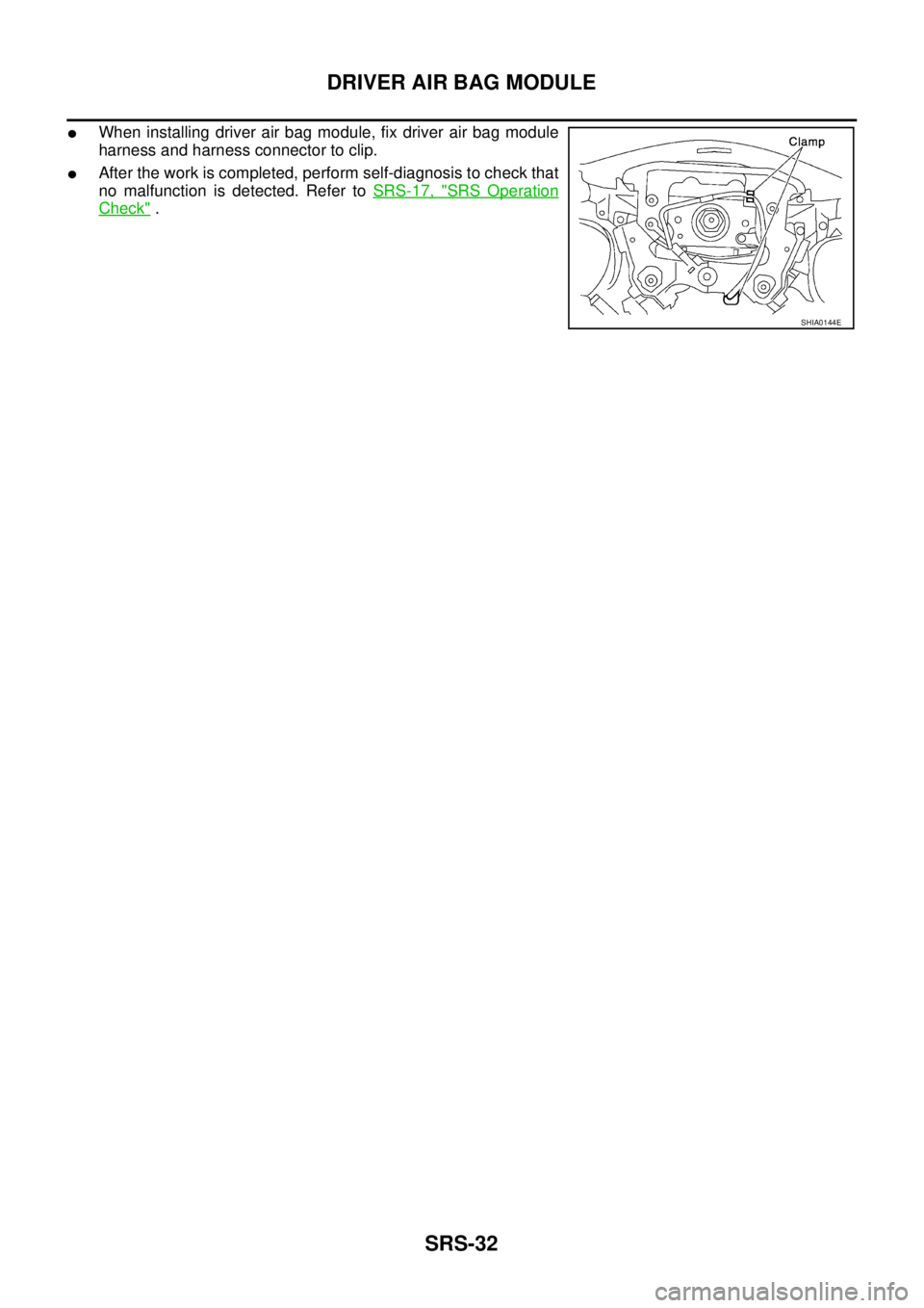
�When installing driver air bag module, fix driver air bag module
harness and harness connector to clip.
�After the work is completed, perform self-diagnosis to check that
no malfunction is detected. Refer to SRS-17, "
SRS Operation
Check" .
SHIA0144E
Page 3566 of 4555
SRS-34
SPIRAL CABLE
9. Remove the horn switch connector and then the spiral cable
connector.
CAUTION:
Also, with the steering linkage disconnectedly cable may snap
by turning the steering wheel beyond the limited number of
turns.
INSTALLATION
Install in the reverse order of removal.
CAUTION:
�The spiral cable may snap due to steering operation if the
cable is installed in an improper position.
�Also, with the steering linkage disconnectedly cable may
snap by turning the steering wheel beyond the limited num-
ber of turns. The spiral cable can be turned to the left about
2.5 turns from the right end position.
�After the work is completed, perform self-diagnosis to
check that no malfunction is detected. Refer to SRS-17,
"SRS Operation Check" .
SHIA0193E
SHIA0145E
Page 3568 of 4555
SRS-36
FRONT PASSENGER AIR BAG MODULE
INSTALLATION
Install in the reverse order of removal.
CAUTION:
�Always work from the side of or under front passenger air bag module.
�After the work is completed, perform self-diagnosis to check that no malfunction is detected.
Refer to SRS-17, "
SRS Operation Check" . TORX bolt (size: T50):
: 19.6 N·m (2.0 kg-m, 14.5 ft-lb)
Hex bolt:
: 24.5 N·m (2.5 kg-m, 18 ft-lb)