Page 3469 of 4555
POWER STEERING FLUID
PS-7
C
D
E
F
H
I
J
K
L
MA
B
PS
5. Stop engine if bubbles and white contamination do not drain out. Perform steps 2 and 3 above after wait-
ing until bubbles and white contamination drain out.
6. Stop the engine, and then check fluid level.
Page 3470 of 4555

PS-8
STEERING WHEEL
STEERING WHEELPFP:48430
On-Vehicle Inspection and ServiceEGS001BY
CHECKING CONDITION OF INSTALLATION
�Check installation conditions of steering gear assembly, front suspension, axle and steering column.
�Check if movement exists when steering wheel is moved up and down, to the left and right and to the axial
direction.
�Check steering gear assembly mounting bolts and nut for looseness. Refer to PS-16, "COMPONENT" .
CHECKING STEERING WHEEL PLAY
�Turn steering wheel so that front wheels come to the straight-ahead position. Start engine and lightly turn
steering wheel to the left and right until front wheels start to move. Measure steering wheel movement on
the outer circumference.
�When the measurement value is outside the standard value, check backlash for each joint of steering col-
umn and installation condition of steering gear assembly.
CHECKING NEUTRAL POSITION STEERING WHEEL
�Make sure that steering gear assembly, steering column and steering wheel are installed in the correct
position.
�Perform neutral position inspection after wheel alignment. Refer to FSU-6, "Wheel Alignment" .
�Set vehicle to the straight-ahead position and confirm steering wheel is in the neutral position.
�Loosen outer socket lock nut and turn inner socket to left and right equally to make fine adjustments if
steering wheel is not in the neutral position.
CHECKING STEERING WHEEL TURNING FORCE
1. Park vehicle on a level and dry surface, set parking brake.
2. Start engine.
3. Bring power steering fluid up to adequate operating temperature. [Make sure temperature of fluid is
approximately 50 to 80°C (122 to 176°F).]
4. Check steering wheel turning force when steering wheel has
been turned 360° from neutral position.
NOTE:
�Multiply the distance (L) from the hook of spring scale to the
center of steering wheel by the measurement value with a
spring scale.
�Perform the following manner when the guideline value is
hard to be measured.
a. Park vehicle on a level and dry surface, set parking brake.
b. Remove driver air bag module. Refer to SRS-30, "
DRIVER AIR BAG MODULE" .
c. Start engine at idle, then check steering wheel turning force with
pre-load gauge [SST].
5. If steering wheel turning force is out of the specification, check
rack sliding force and relief hydraulic pressure of oil pump.
Regarding relief hydraulic pressure of oil pump, refer to PS-27,
"OIL PUMP PULLEY HYDRAULIC PRESSURE INSPECTION" .
a. Disconnect lower shaft and steering knuckle from steering gear
assembly. Refer to FAX-7, "
Removal and Installation" , PS-11,
"COMPONENT" . Steering wheel axial end play : 0 mm (0 in)
Steering wheel play : 0 - 35 mm (0 - 1.38 in)
Steering wheel
turning force: 36 N (3.7 kg, 8.2 lb) or less
Steering wheel
turning force: 706 N·cm (72 kg-cm, 62 in-lb)
SST491B
SGIA1050J
Page 3471 of 4555

STEERING WHEEL
PS-9
C
D
E
F
H
I
J
K
L
MA
B
PS
b. Start and run engine at idle to make sure steering fluid has reached normal operating temperature.
c. While pulling outer socket slowly in ±11 . 5 m m (±0.453 in) range
from neutral position, make sure rack sliding force is within
specification.
d. If rack sliding force is not within specification, overhaul steering
gear assembly.
CHECKING FRONT WHEEL TURNING ANGLE
�Check front wheel turning angle after toe-in inspection. Place
front wheels on turning radius gauges and rear wheels on
stands. Check the maximum inner and outer wheel turning
angles for LH and RH road wheels.
�With the engine at idle, turn steering wheel from full left stop to
full right stop and measure the turning angles.
�Measure rack stroke if angles are outside the specified value.
�Disassemble steering gear assembly to check the cause that
rack stroke is outside of the standard.
�Steering angles are not adjustable. Check steering gear assem-
bly, steering column assembly and front suspension compo-
nents for wear or damage if any of the turning angles are
different from the specified value. Replace any of them, if any
non-standard condition exists.Rack sliding force: 206 - 264 N
(21.0 - 26.9 kg, 46.3 - 59.3 lb)
SST090B
FAA0016D
Inner wheel (Angle: A)Minimum 36° 00′ (36.0°)
Nominal 39° 00′ (39.0°)
Maximum 40° 00′ (40.0°)
Outer wheel (Angle: B) 31° 00′ (31.0°)
SGIA0055E
Rack stroke “L” : 66.5 mm (2.618 in)
SGIA0629J
Page 3475 of 4555
STEERING COLUMN
PS-13
C
D
E
F
H
I
J
K
L
MA
B
PS
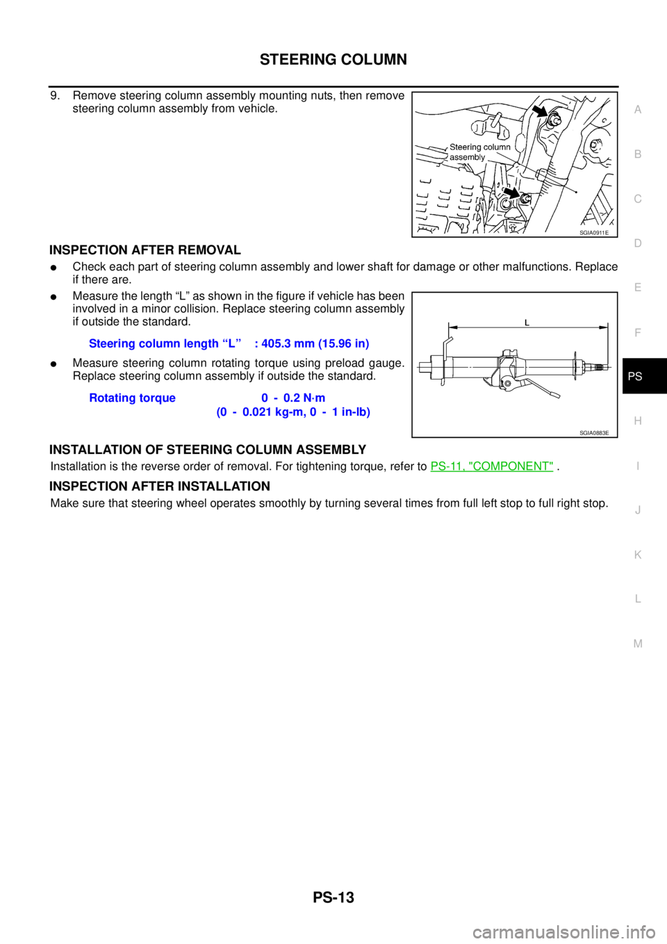
9. Remove steering column assembly mounting nuts, then remove
steering column assembly from vehicle.
INSPECTION AFTER REMOVAL
�Check each part of steering column assembly and lower shaft for damage or other malfunctions. Replace
if there are.
�Measure the length “L” as shown in the figure if vehicle has been
involved in a minor collision. Replace steering column assembly
if outside the standard.
�Measure steering column rotating torque using preload gauge.
Replace steering column assembly if outside the standard.
INSTALLATION OF STEERING COLUMN ASSEMBLY
Installation is the reverse order of removal. For tightening torque, refer to PS-11, "COMPONENT" .
INSPECTION AFTER INSTALLATION
Make sure that steering wheel operates smoothly by turning several times from full left stop to full right stop.
SGIA0911E
Steering column length “L” : 405.3 mm (15.96 in)
Rotating torque 0 - 0.2 N·m
(0 - 0.021 kg-m, 0 - 1 in-lb)
SGIA0883E
Page 3476 of 4555
, and then remove column shaft from jacket tube.
2. Secure adjusting bo")
PS-14
STEERING COLUMN
Disassembly and AssemblyEGS00095
COMPONENT
DISASSEMBLY
1. Remove the lock nut (for securing column shaft), and then remove column shaft from jacket tube.
2. Secure adjusting bolt, then remove lock nut (for securing tilt lever) and adjusting stopper.
3. Loosen adjusting bolt, and then remove tilt lever and tilt lever stopper.
4. Remove adjusting bolt and column mounting bracket from jacket tube.
INSPECTION AFTER DISASSEMBLY
�Check jacket tube and column shaft for deformation or damage. Replace if there are.
�Check tilt mechanism components for malfunction. Replace if there are.
ASSEMBLY
�Assemble in the reverse order of the disassembly. For tightening torque, refer to PS-14, "COMPONENT" .
�Tighten lock nut (for securing tilt lever) to the specified torque so that tilt lever locks when tilt lever turns
from unlock to lock. Refer to PS-14, "
COMPONENT" .
1. Column shaft 2. Jacket tube 3. Adjusting stopper
4. Adjusting bolt 5. Column mounting bracket 6. Tilt lever stopper
7. Tilt lever
SGIA0904E
Page 3477 of 4555
STEERING COLUMN
PS-15
C
D
E
F
H
I
J
K
L
MA
B
PS
INSPECTION AFTER ASSEMBLY
Check tilt mechanism operating rage.
SGIA0884E
Page 3479 of 4555
")
POWER STEERING GEAR AND LINKAGE
PS-17
C
D
E
F
H
I
J
K
L
MA
B
PS
6. Remove steering outer socket from steering knuckle so as not to
damage ball joint boot using the ball joint remover (suitable tool).
CAUTION:
Temporarily tighten the nut to prevent damage to threads
and to prevent the ball joint remover (suitable tool) from
suddenly coming off.
7. Remove high-pressure piping and low-pressure hose of hydrau-
lic piping, and then drain power steering fluid. Refer to PS-37,
"HYDRAULIC LINE" .
8. Remove the power steering tube bracket mounting bolts and
nuts, and then remove power steering tube bracket from steer-
ing gear assembly.
9. Tilt steering gear assembly to prevent any contact with other
parts and then remove it from right side of vehicle.
INSTALLATION
Installation in the reverse order of the removal. For tightening torque, refer to PS-16, "COMPONENT" .
�When installing lower shaft to steering gear, follow the procedure listed below.
–Set rack of steering gear in the neutral position.
NOTE:
To get the neutral position of rack, turn gear sub assembly and measure the distance of inner socket, and
then measure the intermediate position of the distance.
–Align rear cover cap projection with the projection of gear sub assembly.
–Align slit part of lower shaft with the projection of rear cover cap.
And then install it onto rear cover cap of steering gear assembly.
Make sure that the slit part of lower shaft is aligned with both the
projection of rear cover cap and the marking position of gear sub
assembly.
–After installation, bleed air from the steering hydraulic system.
Refer to PS-6, "
Air Bleeding Hydraulic System" .
–Perform final tightening of nuts and bolts on each part under
unladen conditions with tyres on level ground when removing
steering gear assembly. Check wheel alignment. Refer to FSU-
6, "Wheel Alignment" .
–Adjust neutral position of steering angle sensor after checking
wheel alignment. Refer to BRC-52, "
Adjustment of Steering Angle Sensor Neutral Position" .
SGIA1164E
SGIA0912E
SGIA0910E
Page 3482 of 4555
![NISSAN X-TRAIL 2005 Service Repair Manual PS-20
POWER STEERING GEAR AND LINKAGE
9. Drill out the punch crimping part of gear housing assembly outer
rim with a 3 mm (0.12 in) drill bit. [Drill for approximately 1.5 mm
(0.059 in) depth.]
10.](/manual-img/5/57403/w960_57403-3481.png "NISSAN X-TRAIL 2005 Service Repair Manual PS-20
POWER STEERING GEAR AND LINKAGE
9. Drill out the punch crimping part of gear housing assembly outer
rim with a 3 mm (0.12 in) drill bit. [Drill for approximately 1.5 mm
(0.059 in) depth.]
10.")
PS-20
POWER STEERING GEAR AND LINKAGE
9. Drill out the punch crimping part of gear housing assembly outer
rim with a 3 mm (0.12 in) drill bit. [Drill for approximately 1.5 mm
(0.059 in) depth.]
10. Remove end cover assembly with a 36 mm (1.42 in) open head
(suitable tool).
CAUTION:
Do not damage rack assembly surface when removing.
Rack assembly must be replaced if damaged because it
may cause oil leakage.
11. Pull rack assembly together with rack oil seal out from gear
housing assembly.
CAUTION:
Do not damage cylinder inner wall when removing rack
assembly. Gear housing assembly must be replaced if dam-
aged because it may cause oil leakage.
12. Heat rack Teflon ring to approximately 40°C (104°F) with a
dryer, and remove rack Teflon ring and O-ring A from rack
assembly.
CAUTION:
Do not damage rack assembly. Rack assembly must be
replaced if damaged because it may cause oil leakage.
13. Push rack oil seal inside with a 29 mm (1.14 in) socket and an
extension bar to push out rack oil seal from gear housing
assembly.
CAUTION:
Do not damage gear housing assembly and cylinder inner
wall. Gear housing assembly must be replaced if damaged
because it may cause oil leakage.
INSPECTION AFTER DISASSEMBLY
Boot
Check boot for cracks. Replace if there are.
Rack Assembly
Check rack assembly for damage or wear. Replace if there are.
Gear Sub Assembly
�Check pinion gear for damage or wear. Replace if there are.
�Rotate pinion and check for torque variation or rattle. Replace if there are.
STC0013D
SST081B
SGIA0151E
SGIA0179E