Page 3429 of 4555
NAVIGATION SYSTEM
AV-87
C
D
E
F
G
H
I
J
L
MA
B
AV
2. CHECK HARNESS
1. Turn ignition switch OFF.
2. Disconnect NAVI control unit connector and transfer unit connector.
3. Check continuity between and NAVI control unit harness con-
nector M117 terminal 43, 44 * , 45 (Y) and transfer unit harness
connector M111 terminal 9, 11*, 13 (Y).
�*: LHD model (BR), RHD model (R/L)
4. Check continuity between NAVI control unit harness connector
M117 terminal 43, 44*, 45 (Y) and ground.
�*: LHD model (BR), RHD model (R/L)
OK or NG
OK >> Replace NAVI control unit.
NG >> Repair harness or connector.43 - 9 : Continuity should exist.
44* - 11* : Continuity should exist.
45 (Y) - 13 (Y) : Continuity should exist.
43, 44*, 45 (Y) - Ground : Continuity should not exist.
PKIC0534E
Page 3430 of 4555
AV-88
NAVIGATION SYSTEM
Communication Line Check (Between Transfer Unit and Display) EKS00F3C
1. CHECK POWER SUPPLY AND GROUND CIRCUIT
Check system of power supply and ground circuit transfer unit. Refer to AV- 8 3 , "
Power Supply and Ground
Circuit Check for Transfer Unit" .
OK or NG
OK >> GO TO 2.
NG >> Check the malfunctioning parts.
2. CHECK HARNESS
1. Turn ignition switch OFF.
2. Disconnect transfer unit connector and display connector.
3. Check continuity between transfer unit harness connector M111
terminal 19, 20 (L) and display harness connector M112 terminal
17, 16 (L).
4. Check continuity between transfer unit harness connector M111
terminal 19, 20 (R/L) and ground.
OK or NG
OK >> Replace transfer unit.
NG >> Repair harness or connector.19 - 17 : Continuity should exist.
20 (L) - 16 (L) : Continuity should exist.
19, 20 (L) - Ground : Continuity should not exist.
SKIA9225E
Page 3431 of 4555
NAVIGATION SYSTEM
AV-89
C
D
E
F
G
H
I
J
L
MA
B
AV
Vehicle Speed Signal CheckEKS00F3D
1. VEHICLE SPEED OPERATION CHECK
Does speedometer operate normally?
Ye s o r N o
Ye s > > G O T O 2 .
No >> Check combination meter trouble diagnosis. Refer to DI-28, "
Vehicle Speed Signal Inspection
[With ESP]" in “COMBINATION METERS”.
2. HARNESS CHECK
1. Turn the ignition switch OFF.
2. Disconnect NAVI control unit connector and combination meter connector.
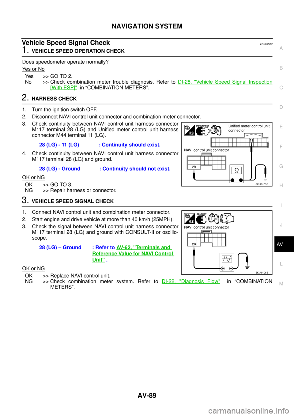
3. Check continuity between NAVI control unit harness connector
M117 terminal 28 (LG) and Unified meter control unit harness
connector M44 terminal 11 (LG).
4. Check continuity between NAVI control unit harness connector
M117 terminal 28 (LG) and ground.
OK or NG
OK >> GO TO 3.
NG >> Repair harness or connector.
3. VEHICLE SPEED SIGNAL CHECK
1. Connect NAVI control unit and combination meter connector.
2. Start engine and drive vehicle at more than 40 km/h (25MPH).
3. Check the signal between NAVI control unit harness connector
M117 terminal 28 (LG) and ground with CONSULT-II or oscillo-
scope.
OK or NG
OK >> Replace NAVI control unit.
NG >> Check combination meter system. Refer to DI-22, "
Diagnosis Flow" in “COMBINATION
METERS”. 28 (LG) - 11 (LG) : Continuity should exist.
28 (LG) - Ground : Continuity should not exist.
SKIA9105E
28 (LG) – Ground : Refer to AV- 6 2 , "Terminals and
Reference Value for NAVI Control
Unit" .
SKIA9106E
Page 3432 of 4555
AV-90
NAVIGATION SYSTEM
Illumination Signal CheckEKS00F3E
1. TAIL LAMP OPERATION CHECK
When lighting switch turned 1st or 2nd position, does tail lamp illuminate?
YES or NO
YES >> GO TO 2.
NO >> Go to tail lamp trouble diagnosis.
2. ILLUMINATION SIGNAL CHECK
Check voltage between NAVI control unit and ground.
OK or NG
OK >> Replace NAVI control unit.
NG >> Repair harness or connector.
Ignition Signal CheckEKS00F3F
1. IGNITION SIGNAL CHECK
1. Turn the ignition switch ON.
2. Check voltage between NAVI control unit harness connector
M117 terminal 26 (G) and ground.
OK or NG
OK >> Replace NAVI control unit.
NG >> Check the following.
�10A fuse [No. 5, located in fuse block (J/B)]
�Harness for open or short between NAVI control unit
and fuse
Terminals
Lighting
switch
positionVoltag e (+)
(–)
Connector Terminal (wire color)
M117 25 (R/L) Ground1st or 2nd
positionBattery voltage
OFF Approx. 0V
SKIA9107E
26 (G) - Ground : Battery voltage
SKIA9108E
Page 3433 of 4555
NAVIGATION SYSTEM
AV-91
C
D
E
F
G
H
I
J
L
MA
B
AV
Reverse Signal CheckEKS00F3G
1. REVERSE LAMP CHECK
Turn the ignition switch ON.
�With the A/T selector lever in R-position, does “R” in the shift position indicator turned on? (With A/T)
�With the shift lever in R-position, are reverse lamps turned on? (With M/T)
YES or NO
YES >> GO TO 2.
NO >> Check “BACK-UP LAMP” system.
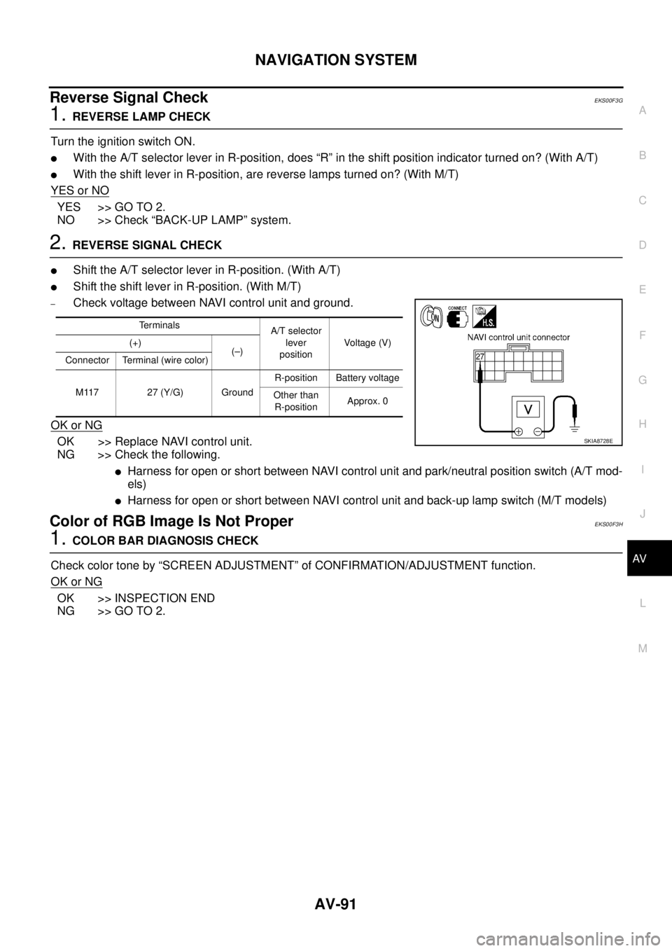
2. REVERSE SIGNAL CHECK
�Shift the A/T selector lever in R-position. (With A/T)
�Shift the shift lever in R-position. (With M/T)
–Check voltage between NAVI control unit and ground.
OK or NG
OK >> Replace NAVI control unit.
NG >> Check the following.
�Harness for open or short between NAVI control unit and park/neutral position switch (A/T mod-
els)
�Harness for open or short between NAVI control unit and back-up lamp switch (M/T models)
Color of RGB Image Is Not ProperEKS00F3H
1. COLOR BAR DIAGNOSIS CHECK
Check color tone by “SCREEN ADJUSTMENT” of CONFIRMATION/ADJUSTMENT function.
OK or NG
OK >> INSPECTION END
NG >> GO TO 2.
Te r m i n a l s
A/T selector
lever
positionVoltage (V) (+)
(–)
Connector Terminal (wire color)
M117 27 (Y/G) GroundR-position Battery voltage
Other than
R-positionApprox. 0
SKIA8728E
Page 3434 of 4555
AV-92
NAVIGATION SYSTEM
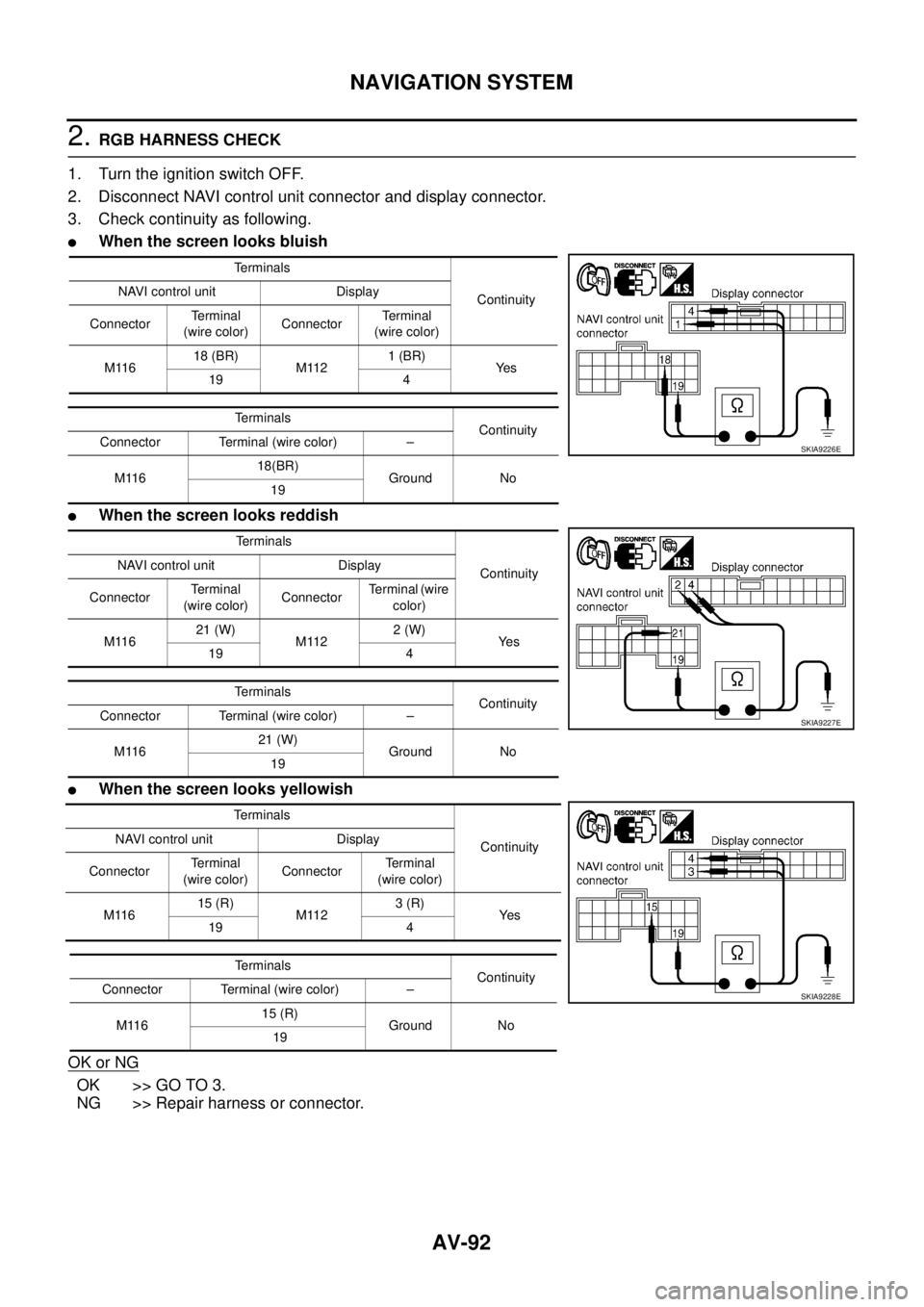
2. RGB HARNESS CHECK
1. Turn the ignition switch OFF.
2. Disconnect NAVI control unit connector and display connector.
3. Check continuity as following.
�When the screen looks bluish
�When the screen looks reddish
�When the screen looks yellowish
OK or NG
OK >> GO TO 3.
NG >> Repair harness or connector.
Terminals
Continuity NAVI control unit Display
ConnectorTerminal
(wire color)ConnectorTerminal
(wire color)
M11618 (BR)
M1121 (BR)
Ye s
19 4
Terminals
Continuity
Connector Terminal (wire color) –
M11618(BR)
Ground No
19
Terminals
Continuity NAVI control unit Display
ConnectorTe r m i n a l
(wire color)ConnectorTerminal (wire
color)
M11621 (W)
M1122 (W)
Ye s
19 4
Terminals
Continuity
Connector Terminal (wire color) –
M11621 (W)
Ground No
19
Terminals
Continuity NAVI control unit Display
ConnectorTerminal
(wire color)ConnectorTerminal
(wire color)
M11615 (R)
M1123 (R)
Ye s
19 4
Terminals
Continuity
Connector Terminal (wire color) –
M11615 (R)
Ground No
19
SKIA9226E
SKIA9227E
SKIA9228E
Page 3435 of 4555
NAVIGATION SYSTEM
AV-93
C
D
E
F
G
H
I
J
L
MA
B
AV
3. RGB SIGNAL CHECK
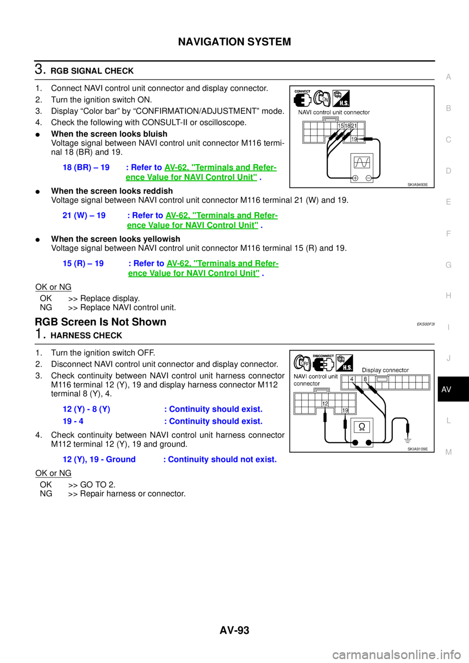
1. Connect NAVI control unit connector and display connector.
2. Turn the ignition switch ON.
3. Display “Color bar” by “CONFIRMATION/ADJUSTMENT” mode.
4. Check the following with CONSULT-II or oscilloscope.
�When the screen looks bluish
Voltage signal between NAVI control unit connector M116 termi-
nal 18 (BR) and 19.
�When the screen looks reddish
Voltage signal between NAVI control unit connector M116 terminal 21 (W) and 19.
�When the screen looks yellowish
Voltage signal between NAVI control unit connector M116 terminal 15 (R) and 19.
OK or NG
OK >> Replace display.
NG >> Replace NAVI control unit.
RGB Screen Is Not ShownEKS00F3I
1. HARNESS CHECK
1. Turn the ignition switch OFF.
2. Disconnect NAVI control unit connector and display connector.
3. Check continuity between NAVI control unit harness connector
M116 terminal 12 (Y), 19 and display harness connector M112
terminal 8 (Y), 4.
4. Check continuity between NAVI control unit harness connector
M112 terminal 12 (Y), 19 and ground.
OK or NG
OK >> GO TO 2.
NG >> Repair harness or connector.18 (BR) – 19 : Refer to AV- 6 2 , "
Terminals and Refer-
ence Value for NAVI Control Unit" .
21 (W) – 19 : Refer to AV- 6 2 , "
Terminals and Refer-
ence Value for NAVI Control Unit" .
15 (R) – 19 : Refer to AV- 6 2 , "
Terminals and Refer-
ence Value for NAVI Control Unit" .
SKIA9493E
12 (Y) - 8 (Y) : Continuity should exist.
19 - 4 : Continuity should exist.
12 (Y), 19 - Ground : Continuity should not exist.
SKIA9109E
Page 3436 of 4555
AV-94
NAVIGATION SYSTEM
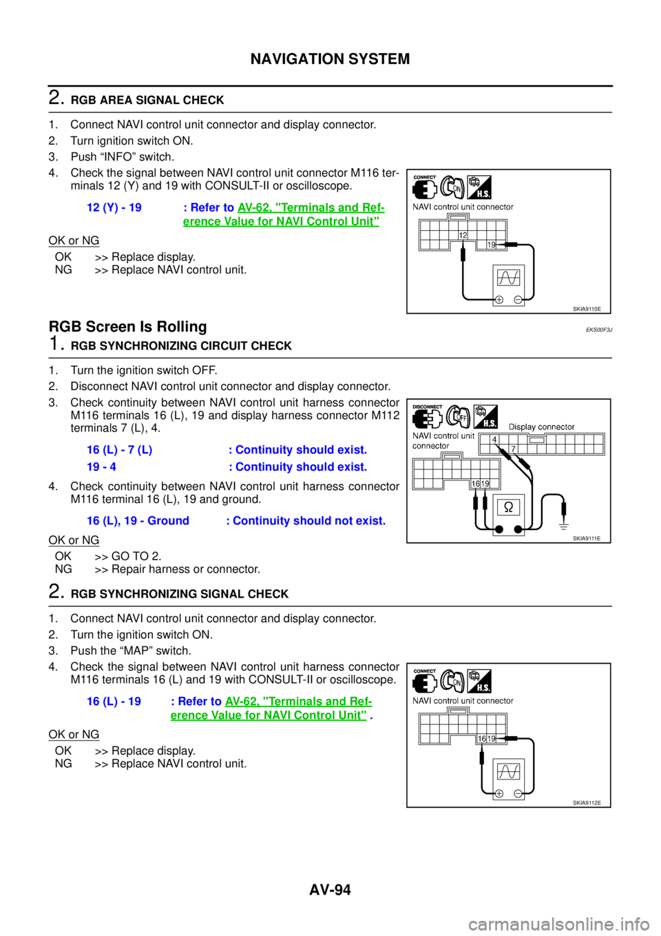
2. RGB AREA SIGNAL CHECK
1. Connect NAVI control unit connector and display connector.
2. Turn ignition switch ON.
3. Push “INFO” switch.
4. Check the signal between NAVI control unit connector M116 ter-
minals 12 (Y) and 19 with CONSULT-II or oscilloscope.
OK or NG
OK >> Replace display.
NG >> Replace NAVI control unit.
RGB Screen Is RollingEKS00F3J
1. RGB SYNCHRONIZING CIRCUIT CHECK
1. Turn the ignition switch OFF.
2. Disconnect NAVI control unit connector and display connector.
3. Check continuity between NAVI control unit harness connector
M116 terminals 16 (L), 19 and display harness connector M112
terminals 7 (L), 4.
4. Check continuity between NAVI control unit harness connector
M116 terminal 16 (L), 19 and ground.
OK or NG
OK >> GO TO 2.
NG >> Repair harness or connector.
2. RGB SYNCHRONIZING SIGNAL CHECK
1. Connect NAVI control unit connector and display connector.
2. Turn the ignition switch ON.
3. Push the “MAP” switch.
4. Check the signal between NAVI control unit harness connector
M116 terminals 16 (L) and 19 with CONSULT-II or oscilloscope.
OK or NG
OK >> Replace display.
NG >> Replace NAVI control unit.12 (Y) - 19 : Refer to AV- 6 2 , "
Terminals and Ref-
erence Value for NAVI Control Unit"
SKIA9110E
16 (L) - 7 (L) : Continuity should exist.
19 - 4 : Continuity should exist.
16 (L), 19 - Ground : Continuity should not exist.
SKIA9111E
16 (L) - 19 : Refer to AV- 6 2 , "Terminals and Ref-
erence Value for NAVI Control Unit" .
SKIA9112E