Page 3162 of 4555
![NISSAN X-TRAIL 2005 Service Repair Manual BRC-114
[ESP/TCS/ABS]
TROUBLE DIAGNOSIS
�When shifting gears
�When driving on slippery road
�During cornering at high speed
�When passing over bumps or grooves (Approx. 50 mm or more)
�When pulling](/manual-img/5/57403/w960_57403-3161.png "NISSAN X-TRAIL 2005 Service Repair Manual BRC-114
[ESP/TCS/ABS]
TROUBLE DIAGNOSIS
�When shifting gears
�When driving on slippery road
�During cornering at high speed
�When passing over bumps or grooves (Approx. 50 mm or more)
�When pulling")
BRC-114
[ESP/TCS/ABS]
TROUBLE DIAGNOSIS
�When shifting gears
�When driving on slippery road
�During cornering at high speed
�When passing over bumps or grooves (Approx. 50 mm or more)
�When pulling away just after starting engine (Approx. 10 km/h or more)
1. SYMPTOM CHECK 1
Check if pedal vibration or operation sounds occur when the engine is started.
OK or NG
OK >> GO TO 2.
NG >> Perform self-diagnosis. Refer to BRC-81, "
SELF-DIAGNOSIS" .
2. SYMPTOM CHECK 2
Check symptoms when electrical component (headlamps, etc.) Switches are operated.
Do symptoms occur?
YES >> Check if there is a radio, antenna, antenna lead wire, or wiring close to the control unit. If there is,
move it farther away.
NG >> GO TO 3. Check wheel sensor and sensor rotor in Refer to BRC-91, "
Inspection 1 Wheel Sensor
System" .
Symptom 6: ESP OFF Indicator Lamp Does Not IlluminateEFS005WR
INSPECTION PROCEDURE
1. ESP OFF INDICATOR LAMP INSPECTION
Disconnect ESP/TCS/ABS control unit connector.
Does ABS warning lamp and ESP OFF indicator lamp illuminate?
YES >> ESP/TCS/ABS control unit malfunction. Repair or replace the control unit.
NO >> Combination meter system malfunction. Check the combination meter.
Symptom 7: SLIP Indicator Lamp Does Not IlluminateEFS005WS
INSPECTION PROCEDURE
1. SLIP INDICATOR LAMP CONNECTOR INSPECTION
Check connectors for ESP/TCS/ABS control unit and meter vehicle-side harness.
Is inspection result OK?
YES >> GO TO 2.
NO >> Repair or replace the disconnected connector.
2. SLIP INDICATOR LAMP POWER CIRCUIT INSPECTION
Disconnect the meter connector. Check that the voltage between the
vehicle-side harness terminal and body ground is battery voltage
(Approx. 12V).
Is inspection result OK?
YES >> GO TO Refer to BRC-109, "Inspection 15 CAN Commu-
nication Circuit, ESP/TCS/ABS Control Unit and Steer-
ing Angle Sensor" .
NO >>
�Fuse inspection
�Inspection for harness and connectors between fuse
block and meter
�Check the power supply circuit (battery and ignition
switch circuit).SFIA2207E
Page 3212 of 4555

ATC-34
TROUBLE DIAGNOSIS
TROUBLE DIAGNOSISPFP:00004
How to Perform Trouble Diagnoses for Quick and Accurate RepairEJS004GO
WORK FLOW
SYMPTOM TABLE
*1ATC-65, "Operational Check"
SHA900E
Symptom Reference Page
A/C system does not come on. Go to Trouble Diagnosis Procedure for A/C System.ATC-67, "
Power
Supply and
Ground Circuit for
Auto Amp."
Air outlet does not change.
Go to Trouble Diagnosis Procedure for Mode Door Motor. (LAN)ATC-73, "Mode
Door Motor Cir-
cuit"Mode door motor does not operate normally.
Discharge air temperature does not change.
Go to Trouble Diagnosis Procedure for Air Mix Door Motor. (LAN)AT C - 7 6 , "
Air Mix
Door Motor Cir-
cuit"Air mix door motor does not operate nor-
mally.
Intake door does not change.
Go to Trouble Diagnosis Procedure for Intake Door Motor. (LAN)AT C - 7 9 , "
Intake
Door Motor Cir-
cuit"Intake door motor does not operate normally.
Blower motor operation is malfunctioning.
Go to Trouble Diagnosis Procedure for Blower Motor.AT C - 8 2 , "
Blower
Motor Circuit"Blower motor operation is malfunctioning
under out of starting fan speed control.
Magnet clutch does not engage. Go to Trouble Diagnosis Procedure for Magnet Clutch.AT C - 8 8 , "
Magnet
Clutch Circuit"
Insufficient cooling Go to Trouble Diagnosis Procedure for Insufficient Cooling.ATC-96, "Insuffi-
cient Cooling"
Insufficient heating Go to Trouble Diagnosis Procedure for Insufficient Heating.ATC-105, "Insuffi-
cient Heating"
Noise Go to Trouble Diagnosis Procedure for Noise.ATC-107, "Noise"
Self-diagnosis cannot be performed. Go to Trouble Diagnosis Procedure for Self-diagnosis.ATC-108, "Self-
Diagnosis"
Page 3235 of 4555

TROUBLE DIAGNOSIS
ATC-57
C
D
E
F
G
H
I
K
L
MA
B
AT C
Self-diagnosis FunctionEJS004GT
DESCRIPTION
The self-diagnostic system diagnoses sensors, door motors, blower motor, etc. by system line.
Self-diagnosis is step-1 to 7. There are two ways of changing method during self-diagnosis.
�Switching to self-diagnosis step-1 to 4.
Shifting from usual control to the self-diagnostic system is accomplished by starting the engine (turning
the ignition switch from OFF to ON) and pressing A/C switch for at least 5 seconds. The A/C switch must
be pressed within 10 seconds after starting the engine (ignition switch is turned ON). This system will be
canceled by either pressing intake switch or turning the ignition switch OFF. Shifting from one step to
another is accomplished be means of turning fan control dial, as required.
�Switching to self-diagnosis step-5 to 7 (Auxiliary mechanism).
Shifting from usual control to the self-diagnostic system is accomplished by starting the engine (turning
the ignition switch from OFF to ON) and pressing intake switch for at least 5 seconds. The intake switch
must be pressed within 10 seconds after starting the engine (ignition switch is turned ON). This system
will be canceled by either pressing A/C switch or turning the ignition switch OFF. Shifting from one step to
another is accomplished by means of turning fan control dial, as required.
Page 3237 of 4555

1. Set the fan control dial to OFF position.
2. Turn ignition switch")
TROUBLE DIAGNOSIS
ATC-59
C
D
E
F
G
H
I
K
L
MA
B
AT C
FUNCTION CONFIRMATION PROCEDURE
1. SET IN SELF-DIAGNOSTIC MODE (STEP-1 TO 4)
1. Set the fan control dial to OFF position.
2. Turn ignition switch ON.
3. Set in self-diagnostic mode as follows. Within 10 seconds after starting engine (ignition switch is turned
ON.), press A/C switch for at least 5 seconds.
CAUTION:
If battery voltage drops below 12V during diagnosis step-3, actuator speed becomes slower and as a
result, the system may generate an error even when operation is usual. To avoid this, start engine
before performing this diagnosis.
>> GO TO 2.
2. STEP-1: LEDS ARE CHECKED
Check intake and A/C switch LEDs illumination.
OK >> GO TO 3.
NG >> Refer to ATC-108, "
Self-Diagnosis" .
3. CHECK TO ADVANCE SELF-DIAGNOSIS STEP-2
1. Turn fan control dial to AUTO position.
CAUTION:
When switched to STEP-2, LED of REC position blinks for
approximately 25 seconds.
2. Advance to self-diagnosis STEP-2?
Check A/C switch LED illumination.
YES >> GO TO 4.
NO >> Replace controller.
4. CHECK TO RETURN SELF-DIAGNOSIS STEP-1
Turn fan control dial to OFF position.
Return to self
-diagnosis STEP-1?
YES >> GO TO 5.
NO >> Replace controller.
SJIA0389E
SJIA0390E
Page 3241 of 4555

TROUBLE DIAGNOSIS
ATC-63
C
D
E
F
G
H
I
K
L
MA
B
AT C
AUXILIARY MECHANISM: TEMPERATURE SETTING TRIMMER
The trimmer compensates for differences in range of ±3°C between temperature setting (Temperature control
dial position) and temperature felt by driver.
Operating procedures for this trimmer are as follows:
1. Set temperature at 25°C.
2. Set fan control dial to OFF.
3. Turn ignition switch ON.
4. Set in self-diagnostic mode as follows. Within 10 seconds after starting engine (ignition switch is turned
ON.), press intake switch for at least 5 seconds.
5. Turn temperature control dial as desired. Temperature will change at a rate of 1°C each time a dial is
turned.
When battery cable is disconnected, trimmer operation is canceled. Temperature set becomes that of initial
condition, i.e. 0°C.
AUXILIARY MECHANISM: FOOT POSITION SETTING TRIMMER
Wind distribution ratio in FOOT mode can be set.
Operating procedures for this trimmer are as follows:
1. Set temperature at 25°C.
2. Set fan control dial to AUTO.
3. Turn ignition switch ON.
4. Set in self-diagnostic mode as follows. Within 10 seconds after starting engine (ignition switch is turned
ON.), press intake switch for at least 5 seconds.
5. Turn temperature control dial as desired.
Setting temperatureLED status of each switch
FRE REC A/C
−3°CON ON ON
−2°CON ON OFF
−1°CON OFF ON
0°C (Initial setting) OFF OFF OFF
1°COFFOFF ON
2°COFF ON OFF
3°C OFF ON ON
RJIA2825E
Page 3242 of 4555

ATC-64
TROUBLE DIAGNOSIS
AUXILIARY MECHANISM: INLET PORT MEMORY FUNCTION
When ignition switch is turned from OFF to ON, inlet port can be set to AUTO or manual.
Operating procedures for this trimmer are as follows:
1. Set fan control dial to 1st-25th speed.
2. Turn ignition switch ON.
3. Set in self-diagnostic mode as follows. Within 10 seconds after starting engine (ignition switch is turned
ON.), press intake switch for at least 5 seconds.
4. Press intake switch as desired.
Ty p eLED status of each switch
FRE REC A/C
Type-A (initial setting) OFF OFF ON
Ty p e - B O F F O N OF F
Ty p e - C O F F O N O N
Ty p e - D ON O F F OF F
LED status
of FRE
positionLED status
of REC posi-
tionSetting status
Setting changeover method
FRE REC
OFF OFF AUTO control AUTO control
Intake SW: ON OFF ON AUTO control (Initial setting)Manual REC status is memorized.
(Initial setting)
ON OFF Manual FRE status is memorized. AUTO control
ON ON Manual FRE status is memorized. Manual REC status is memorized.
Page 3260 of 4555
ATC-82
TROUBLE DIAGNOSIS
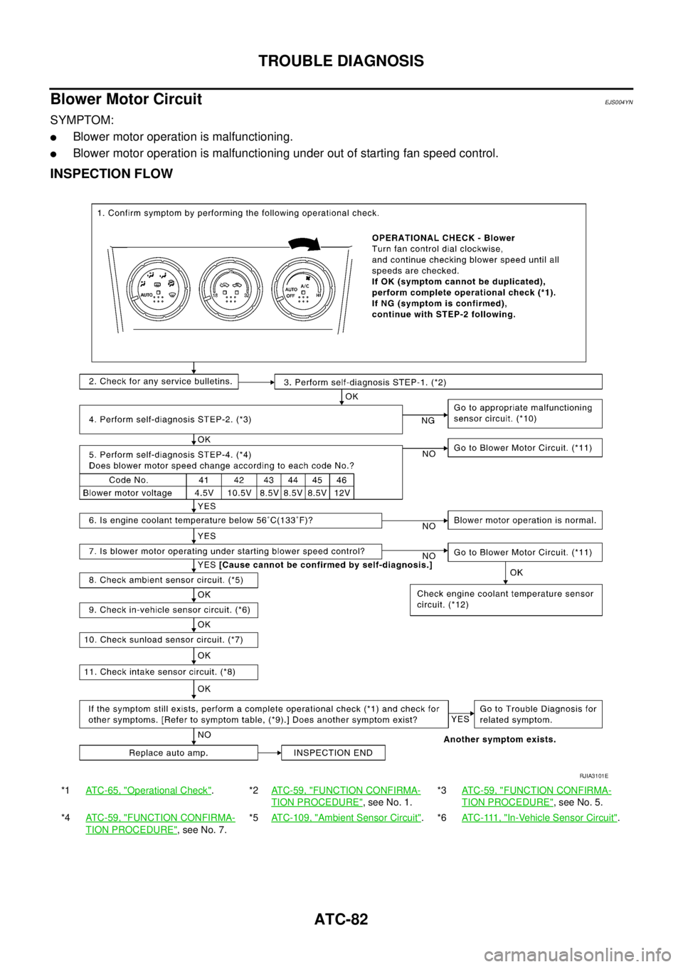
Blower Motor CircuitEJS004YN
SYMPTOM:
�Blower motor operation is malfunctioning.
�Blower motor operation is malfunctioning under out of starting fan speed control.
INSPECTION FLOW
*1ATC-65, "Operational Check".*2ATC-59, "FUNCTION CONFIRMA-
TION PROCEDURE", see No. 1.*3ATC-59, "
FUNCTION CONFIRMA-
TION PROCEDURE", see No. 5.
*4ATC-59, "
FUNCTION CONFIRMA-
TION PROCEDURE", see No. 7.*5ATC-109, "
Ambient Sensor Circuit".*6AT C - 111 , "In-Vehicle Sensor Circuit".
RJIA3101E
Page 3262 of 4555

In a cold start up condition where the engine coolant temperature is below 56°C (133°F), the")
ATC-84
TROUBLE DIAGNOSIS
Starting Fan Speed Control
Start Up from COLD SOAK Condition (Automatic mode)
In a cold start up condition where the engine coolant temperature is below 56°C (133°F), the blower will not
operate for a short period of time (up to 150 seconds). The exact start delay time varies depending on the
ambient and engine coolant temperature.
In the most extreme case (very low ambient) the blower starting delay will be 150 seconds as described
above. After this delay, the blower will operate at low speed until the engine coolant temperature rises above
56°C (133°F), and then the blower speed will increase to the objective speed.
Start Up from Usual or HOT SOAK Condition (Automatic mode)
The blower will begin operation momentarily after the A/C switch is pushed. The blower speed will gradually
rise to the objective speed over a time period of 3 seconds or less (actual time depends on the objective
blower speed).
Blower Speed Compensation
Sunload
When the in-vehicle temperature and the set temperature are very close, the blower will be operating at low
speed. The low speed will vary depending on the sunload. During conditions of low or no sunload, the blower
low speed is usual low speed (approx. 4V). During high sunload conditions, the auto amp. causes the blower
fan speed to increase.(Approx. 7V)
Fan Speed Control Specification
COMPONENT DESCRIPTION
Fan Control Amp.
The fan control amp. is located on the intake unit. The fan control
amp. receives a gate voltage from the auto amp. to steplessly main-
tain the blower fan motor voltage in the 4 to 12 volt range.
DIAGNOSTIC PROCEDURE FOR BLOWER MOTOR
SYMPTOM: Blower motor operation is malfunctioning.
RJIA0522E
RJIA0523E
RHA467GA