2005 NISSAN NAVARA lock
[x] Cancel search: lockPage 2949 of 3171
SRS-40
FRONT PASSENGER AIR BAG MODULE
FRONT PASSENGER AIR BAG MODULE
PFP:K8515
Removal and InstallationEHS001XU
The passenger air bag module originally installed in the vehicle uses direct-connect style harness connectors.
Service replacement passenger air bag modules use tab-locking style harness connectors. If the passenger
air bag module is replaced or if the direct-connect harness connectors are damaged, the vehicle wiring har-
ness must be modified to allow connection of the service replacement passenger air bag module. Refer to
SRS-41, "
WIRING HARNESS MODIFICATION"for wiring harness modification procedure.
REMOVAL
CAUTION:
lDo not attempt to repair or replace damaged direct-connect front passenger air bag module con-
nectors. If a direct-connect harness connector is damaged, the front passenger air bag must be
replaced and the wiring harness modified.
lBefore servicing SRS, turn the ignition switch off, disconnect both battery cables and wait at least
3 minutes.
lAlways work from the side of or under front passenger air bag module.
1. Remove the glove box, then remove instrument panel. Refer toIP-10, "
INSTRUMENT PANEL ASSEM-
BLY".
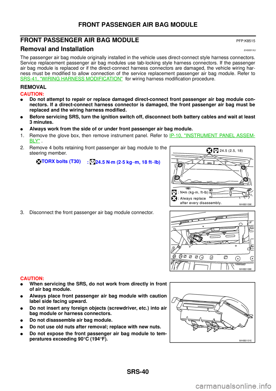
2. Remove 4 bolts retaining front passenger air bag module to the
steering member.
3. Disconnect the front passenger air bag module connector.
CAUTION:
lWhen servicing the SRS, do not work from directly in front
of air bag module.
lAlways place front passenger air bag module with caution
label side facing upward.
lDo not insert any foreign objects (screwdriver, etc.) into air
bag module or harness connectors.
lDo not disassemble air bag module.
lDo not use old nuts after removal; replace with new nuts.
lDo not expose the front passenger air bag module to tem-
peratures exceeding 90°C(194°F). TORX bolts (T30)
: 24.5 N·m (2·5 kg-m, 18 ft-lb)
MHIB0109E
MHIB0108E
MHIB0101E
Page 2950 of 3171
FRONT PASSENGER AIR BAG MODULE
SRS-41
C
D
E
F
G
I
J
K
L
MA
B
SRS
lReplace the air bag module if it has been dropped or sus-
tainedanimpact.
lDo not allow oil, grease or water to come in contact with the
air bag module.
lFor removal/installation of the direct-connect SRS connec-
tors, refer toSRS-8, "
Direct-Connect SRS Component Con-
nectors".
INSTALLATION
Original Passenger Air Bag Module
To install, reverse the removal procedure.
lFor removal/installation of the direct-connect SRS connectors, refer toSRS-8, "Direct-Connect SRS Com-
ponent Connectors".
CAUTION:
lAlways work from the side of or under front passenger air bag module.
lAfter the work is completed, perform self-diagnosis to check that no malfunction is detected.
Refer toSRS-18, "
SRS Operation Check".
Service Replacement Passenger Air Bag Module
1. Install the instrument panel assembly. Refer toIP-10, "INSTRUMENT PANEL ASSEMBLY".
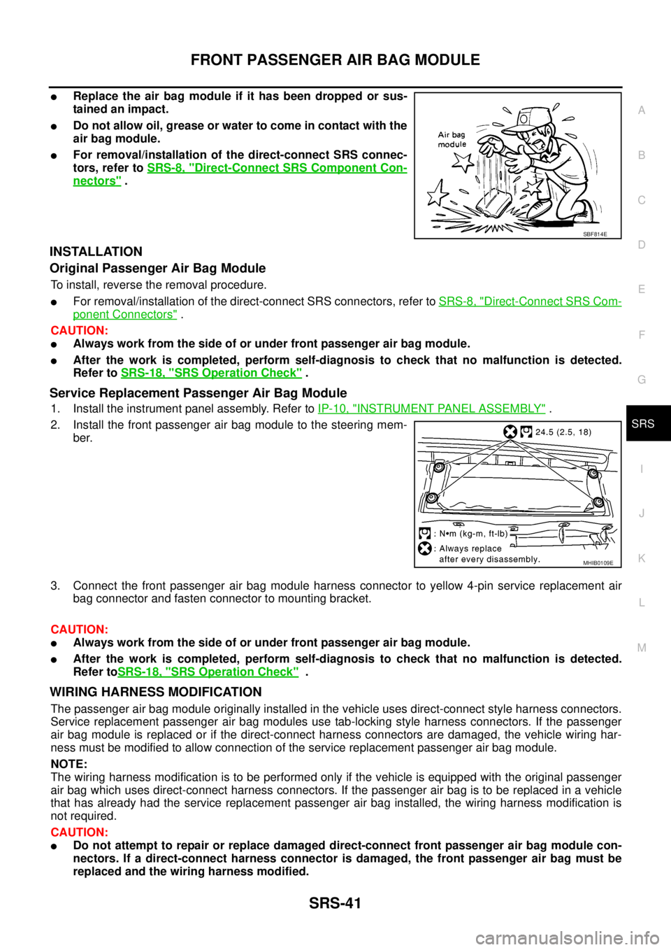
2. Install the front passenger air bag module to the steering mem-
ber.
3. Connect the front passenger air bag module harness connector to yellow 4-pin service replacement air
bag connector and fasten connector to mounting bracket.
CAUTION:
lAlways work from the side of or under front passenger air bag module.
lAfter the work is completed, perform self-diagnosis to check that no malfunction is detected.
Refer toSRS-18, "
SRS Operation Check".
WIRING HARNESS MODIFICATION
The passenger air bag module originally installed in the vehicle uses direct-connect style harness connectors.
Service replacement passenger air bag modules use tab-locking style harness connectors. If the passenger
air bag module is replaced or if the direct-connect harness connectors are damaged, the vehicle wiring har-
ness must be modified to allow connection of the service replacement passenger air bag module.
NOTE:
The wiring harness modification is to be performed only if the vehicle is equipped with the original passenger
air bag which uses direct-connect harness connectors. If the passenger air bag is to be replaced in a vehicle
that has already had the service replacement passenger air bag installed, the wiring harness modification is
not required.
CAUTION:
lDo not attempt to repair or replace damaged direct-connect front passenger air bag module con-
nectors. If a direct-connect harness connector is damaged, the front passenger air bag must be
replaced and the wiring harness modified.
SBF814E
MHIB0109E
Page 2958 of 3171
DISPOSAL OF AIR BAG MODULE AND SEAT BELT PRE-TENSIONER
SRS-49
C
D
E
F
G
I
J
K
L
MA
B
SRS
DISPOSAL OF AIR BAG MODULE AND SEAT BELT PRE-TENSIONERPFP:00014
Caution for Air Bag Module and Seat Belt Pre-tensionerEHS001Y2
lBefore disposing of air bag module, seat belt pre-tensioner or vehicle equipped with such systems, deploy
the systems. If such systems have already been deployed due to an accident, dispose of them as indi-
cated in “SRS-49, "
DISPOSAL OF AIR BAG MODULE AND SEAT BELT PRE-TENSIONER".
lWhen deploying the air bag module or seat belt pre-tensioner, always use the Special Service Tool
Deployment tool [KV99106400].
lWhen deploying the air bag module or seat belt pre-tensioner, stand at least 5 m (16 ft) away from the
component being deployed.
lWhen deploying air bag module or seat belt pre-tensioner, a fairly loud noise is made, followed by smoke
being released. The smoke is not poisonous, however, be careful not to inhale smoke since it irritates the
throat and can cause choking.
lOnly deploy one air bag module or seat belt pre-tensioner at a time.
lDue to heat, leave deployed air bag module unattended for at least 30 minutes after deployment. Leave
deployed seat belt pre-tensioner unattended for at least 10 minutes after deployment.
lBe sure to wear gloves when handling a deployed air bag module or seat belt pre-tensioner.
lNever apply water to the deployed air bag module or seat belt pre-tensioner.
lWash your hands thoroughly after finishing work.
lPlace the vehicle outdoors with an open space of at least 6 m (20 ft) on all sides when deploying air bag
module or seat belt pre-tensioner while mounted in vehicle.
lUse a voltmeter to make sure the vehicle battery is fully charged.
lDo not dispose of the air bag module or seat belt pre-tensioner undeployed.
CHECKING DEPLOYMENT TOOL
Connecting to Battery
CAUTION:
The battery must show voltage of 9.6V or more.
Remove the battery from the vehicle and place it on dry wood blocks
approximately 5 m (16 ft) away from the vehicle.
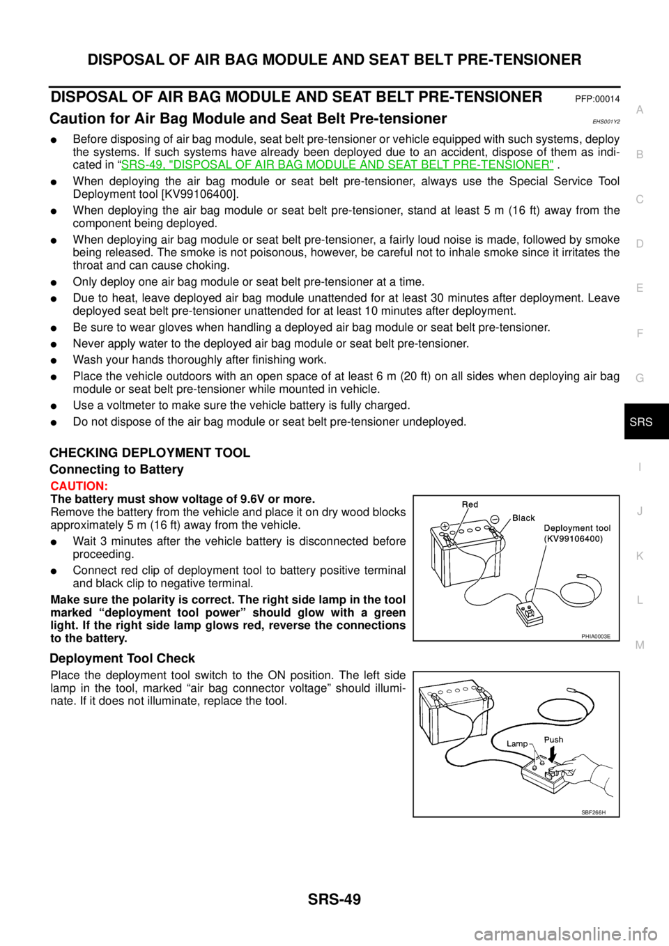
lWait 3 minutes after the vehicle battery is disconnected before
proceeding.
lConnect red clip of deployment tool to battery positive terminal
and black clip to negative terminal.
Makesurethepolarityiscorrect.Therightsidelampinthetool
marked “deployment tool power” should glow with a green
light. If the right side lamp glows red, reverse the connections
to the battery.
Deployment Tool Check
Place the deployment tool switch to the ON position. The left side
lamp in the tool, marked “air bag connector voltage” should illumi-
nate. If it does not illuminate, replace the tool.
PHIA0003E
SBF266H
Page 2975 of 3171
TF-8
PREPARATION
PREPARATION
PFP:00002
Special Service ToolsEDS0031E
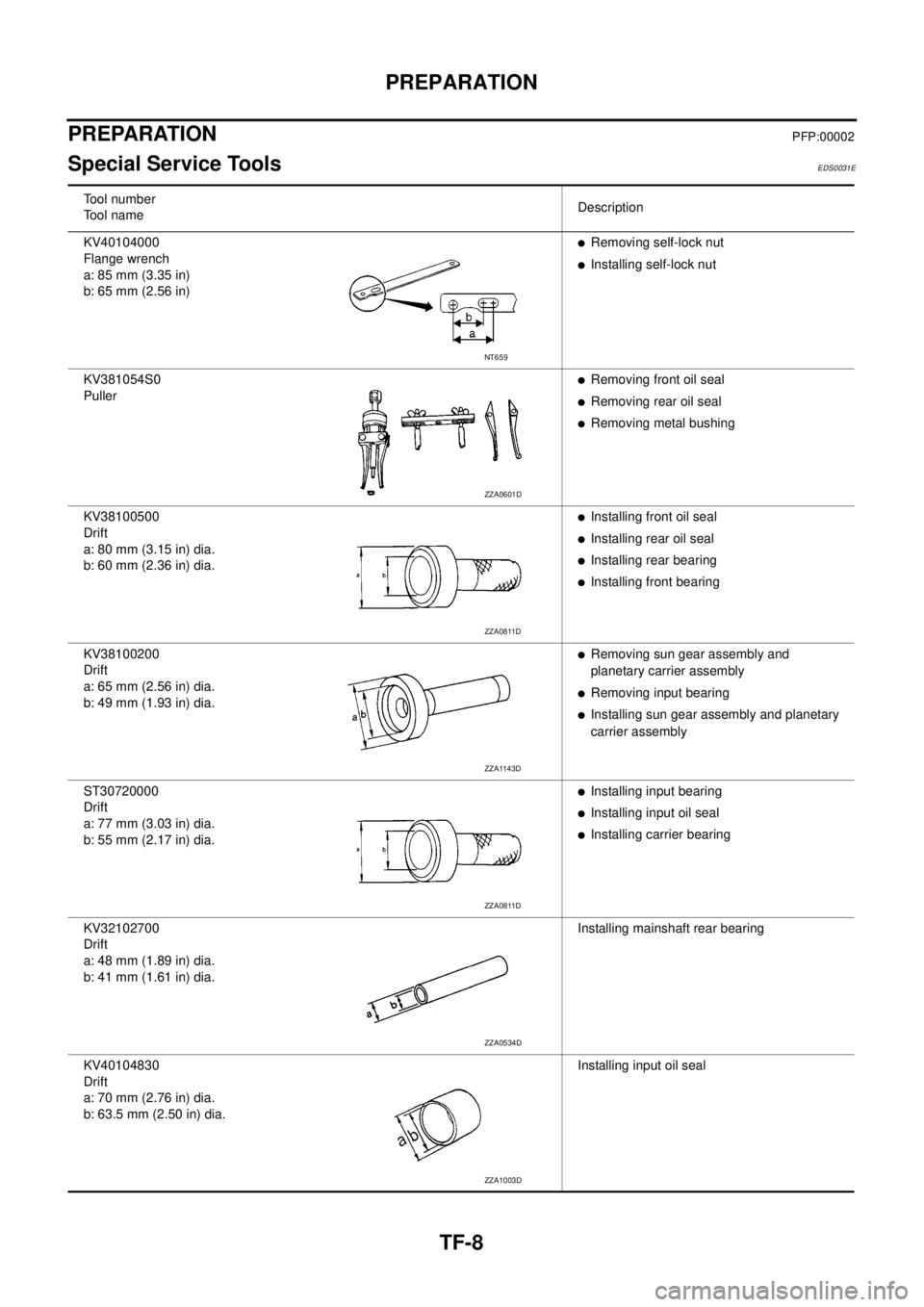
Tool number
Tool nameDescription
KV40104000
Flange wrench
a: 85 mm (3.35 in)
b: 65 mm (2.56 in)
lRemoving self-lock nut
lInstalling self-lock nut
KV381054S0
Puller
lRemoving front oil seal
lRemoving rear oil seal
lRemoving metal bushing
KV38100500
Drift
a: 80 mm (3.15 in) dia.
b: 60 mm (2.36 in) dia.
lInstalling front oil seal
lInstalling rear oil seal
lInstalling rear bearing
lInstalling front bearing
KV38100200
Drift
a: 65 mm (2.56 in) dia.
b: 49 mm (1.93 in) dia.
lRemoving sun gear assembly and
planetary carrier assembly
lRemoving input bearing
lInstalling sun gear assembly and planetary
carrier assembly
ST30720000
Drift
a: 77 mm (3.03 in) dia.
b: 55 mm (2.17 in) dia.
lInstalling input bearing
lInstalling input oil seal
lInstalling carrier bearing
KV32102700
Drift
a: 48 mm (1.89 in) dia.
b: 41 mm (1.61 in) dia.Installing mainshaft rear bearing
KV40104830
Drift
a: 70 mm (2.76 in) dia.
b: 63.5 mm (2.50 in) dia.Installing input oil seal
NT659
ZZA0601D
ZZA0811D
ZZA1143D
ZZA0811D
ZZA0534D
ZZA1003D
Page 3006 of 3171
![NISSAN NAVARA 2005 Repair Workshop Manual TROUBLE DIAGNOSIS
TF-39
C
E
F
G
H
I
J
K
L
MA
B
TF
2WDSWITCH[ON/
OFF]Input condition from 4WD
shift switch4WD shift switch: 2WD ON
4WD shift switch: 4H and 4LO OFF
4H SWITCH [ON/OFF]Input condition fro NISSAN NAVARA 2005 Repair Workshop Manual TROUBLE DIAGNOSIS
TF-39
C
E
F
G
H
I
J
K
L
MA
B
TF
2WDSWITCH[ON/
OFF]Input condition from 4WD
shift switch4WD shift switch: 2WD ON
4WD shift switch: 4H and 4LO OFF
4H SWITCH [ON/OFF]Input condition fro](/manual-img/5/57362/w960_57362-3005.png)
TROUBLE DIAGNOSIS
TF-39
C
E
F
G
H
I
J
K
L
MA
B
TF
2WDSWITCH[ON/
OFF]Input condition from 4WD
shift switch4WD shift switch: 2WD ON
4WD shift switch: 4H and 4LO OFF
4H SWITCH [ON/OFF]Input condition from 4WD
shift switch4WD shift switch: 4H ON
4WD shift switch: 2WD and 4LO OFF
4L SWITCH [ON/OFF]Input condition from 4WD
shift switch4WD shift switch: 4LO ON
4WD shift switch: 2WD and 4H OFF
4L POSI SW [ON/OFF] Condition of 4LO switch
lVehicle stopped
lEngine running
lFor A/T models, A/T
selector lever “N” posi-
tion with brake pedal
depressed.
lFor M/T models, M/T
shift lever neutral posi-
tion with clutch and
brake pedal depressed.4WD shift switch: 4LO ON
Except the above OFF
ATP SWITCH [ON/OFF] Condition of ATP switch
lVehicle stopped
lEngine running
lA/T selector lever “N”
position with brake
pedal depressed.4WD shift switch:
4H to 4LO or 4LO to 4H
(While actuator motor is
operating.)ON
Except the above OFF
WAIT DETCT SW [ON/
OFF]Condition of wait detection
switch
lVehicle stopped
lEngine running
lFor A/T models, A/T
selector lever “N” posi-
tion with brake pedal
depressed.
lFor M/T models, M/T
shift lever neutral posi-
tion with clutch and
brake pedal depressed.4WD shift switch:
4H and 4LOON
4WD shift switch: 2WD OFF
4WD MODE [2H/4H/4L]Control status of 4WD
(Output condition of 4WD
shift indicator lamp and
4LO indicator lamp)4WD shift switch
(Engine running)2WD 2H
4H 4H
4LO 4L
VHCL/S COMP [km/h]
or [mph]Vehicle speedVehicle stopped 0 km/h (0 mph)
Vehicle running
CAUTION:
Check air pressure of tires under standard condi-
tion.Approximately
equal to the indica-
tion on speedome-
ter (Inside of±10%)
SHIFT ACT 1 [ON/OFF]Output condition to actua-
tor motor (clockwise)
lVehicle stopped
lEngine running
lFor A/T models, A/T
selector lever “N” posi-
tion with brake pedal
depressed.
lFor M/T models, M/T
shift lever neutral posi-
tion with clutch and
brake pedal depressed.4WD shift switch:
2WDto4Hor4Hto4LO
or 2WD to 4LOON
Except the above OFF Monitored item [Unit] Content Condition Display value
Page 3007 of 3171
![NISSAN NAVARA 2005 Repair Workshop Manual TF-40
TROUBLE DIAGNOSIS
SHIFT AC MON1 [ON/
OFF]Check signal for transfer
control unit signal output
lVehicle stopped
lEngine running
lFor A/T models, A/T
selector lever “N” posi-
tion with brake p NISSAN NAVARA 2005 Repair Workshop Manual TF-40
TROUBLE DIAGNOSIS
SHIFT AC MON1 [ON/
OFF]Check signal for transfer
control unit signal output
lVehicle stopped
lEngine running
lFor A/T models, A/T
selector lever “N” posi-
tion with brake p](/manual-img/5/57362/w960_57362-3006.png)
TF-40
TROUBLE DIAGNOSIS
SHIFT AC MON1 [ON/
OFF]Check signal for transfer
control unit signal output
lVehicle stopped
lEngine running
lFor A/T models, A/T
selector lever “N” posi-
tion with brake pedal
depressed.
lFor M/T models, M/T
shift lever neutral posi-
tion with clutch and
brake pedal depressed.4WD shift switch:
2WDto4Hor4Hto4LO
or 2WD to 4LOON
Except the above OFF
SHIFT ACT 2 [ON/OFF]Output condition to actua-
tor motor (counterclock-
wise)
lVehicle stopped
lEngine running
lFor A/T models, A/T
selector lever “N” posi-
tion with brake pedal
depressed.
lFor M/T models, M/T
shift lever neutral posi-
tion with clutch and
brake pedal depressed.4WD shift switch:
4LOto4Hor4Hto2WD
or 4LO to 2WDON
Except the above OFF
SHIFT AC MON2 [ON/
OFF]Check signal for transfer
control unit signal output
lVehicle stopped
lEngine running
lFor A/T models, A/T
selector lever “N” posi-
tion with brake pedal
depressed.
lFor M/T models, M/T
shift lever neutral posi-
tion with clutch and
brake pedal depressed.4WD shift switch:
4LOto4Hor4Hto2WD
or 4LO to 2WDON
Except the above OFF
SHIFT ACT/R MON
[ON/OFF]Operating condition of
actuator motor relay (inte-
grated in transfer control
unit)
lVehicle stopped
lEngine running
lFor A/T models, A/T
selector lever “N” posi-
tion with brake pedal
depressed.
lFor M/T models, M/T
shift lever neutral posi-
tion with clutch and
brake pedal depressed.When 4WD shift switch is
operatedON
When 4WD shift switch is
not operatedOFF
SHIFT POS SW1 [ON/
OFF]Condition of actuator posi-
tion switch 1
lVehicle stopped
lEngine running
lFor A/T models, A/T
selector lever “N” posi-
tion with brake pedal
depressed.
lFor M/T models, M/T
shift lever neutral posi-
tion with clutch and
brake pedal depressed.4WD shift switch:
2WD and 4LOON
4WD shift switch: 4H OFF
SHIFT POS SW2 [ON/
OFF]Condition of actuator posi-
tion switch 24WD shift switch: 4LO ON
4WD shift switch:
2WD and 4HOFF
SHIFT POS SW3 [ON/
OFF]Condition of actuator posi-
tion switch 34WD shift switch:
2WD and 4HON
4WD shift switch: 4LO OFF
SHIFT POS SW4 [ON/
OFF]Condition of actuator posi-
tion switch 44WD shift switch:
4H and 4LOON
4WD shift switch: 2WD OFF
4WD FAIL LAMP [ON/
OFF]4WD warning lamp condi-
tion4WD warning lamp: ON ON
4WD warning lamp: OFF OFF Monitored item [Unit] Content Condition Display value
Page 3014 of 3171

TROUBLE DIAGNOSIS
TF-47
C
E
F
G
H
I
J
K
L
MA
B
TF
DATA MONITOR MODE
Operation Procedure
1. Perform “CONSULT-II SETTING PROCEDURE”. Refer toTF-44, "CONSULT-II SETTING PROCEDURE"
.
2. Touch “DATA MONITOR”.
3. Select from “SELECT MONITOR ITEM”, screen of data monitor mode is displayed.
NOTE:
When malfunction is detected, CONSULT-II performs REAL-TIME DIAGNOSIS.
Also, any malfunction detected while in this mode will be displayed in real time.
Display Item List
´: Standard –: Not applicable
Monitored item (Unit)Monitor item selection
Remarks
ECU INPUT
SIGNALSMAIN
SIGNALSSELECTION
FROM MENU
VHCL/S SEN·FR [km/h] or [mph]´–´For ABS models, wheel speed calculated
by ABS actuator and electric unit (control
unit). Signal input with CAN communica-
tion line.
VHCL/S SEN·RR [km/h] or [mph]´–´For ABS models, wheel speed calculated
by TCM. Signal input with CAN communi-
cation line.
ENGINE SPEED [rpm]´–´Engine speed is displayed.
Signal input with CAN communication line.
BATTERY VOLT [V]´–´Power supply voltage for transfer control
unit.
2WD SWITCH [ON/OFF]´–´
4WD shift switch signal status is dis-
played.
(4L means 4LO of 4WD shift switch.) 4H SWITCH [ON/OFF]´–´
4L SWITCH [ON/OFF]´–´
4L POSI SW [ON/OFF]´–´This means 4LO switch.
4LO switch signal status is displayed.
ATP SWITCH [ON/OFF]´–´ATP switch signal status is displayed.
WAIT DETCT SW [ON/OFF]´–´Wait detection switch signal status is dis-
played.
4WD MODE [2H/4H/4L] –´´Control status of 4WD recognized by
transfer control unit. (2WD, 4H or 4LO)
VHCL/S COMP [km/h] or [mph] –´´Vehicle speed recognized by transfer con-
trol unit.
SHIFT ACT 1 [ON/OFF] –´´Output condition to actuator motor (clock-
wise)
SHIFT AC MON 1 [ON/OFF] – –´Check signal for transfer control unit sig-
nal output
SHIFT ACT 2 [ON/OFF] –´´Output condition to actuator motor (coun-
terclockwise)
SHIFT AC MON 2 [ON/OFF] – –´Check signal for transfer control unit sig-
nal output
SFT ACT/R MON [ON/OFF] – –´Operating condition of actuator motor
relay (integrated in transfer control unit)
SHIFT POS SW 1 [ON/OFF]´–´Condition of actuator position switch 1
SHIFT POS SW 2 [ON/OFF]´–´Condition of actuator position switch 2
SHIFT POS SW 3 [ON/OFF]´–´Condition of actuator position switch 3
SHIFT POS SW 4 [ON/OFF]´–´Condition of actuator position switch 4
Page 3020 of 3171
TROUBLE DIAGNOSIS FOR SYSTEM
TF-53
C
E
F
G
H
I
J
K
L
MA
B
TF
DIAGNOSTIC PROCEDURE
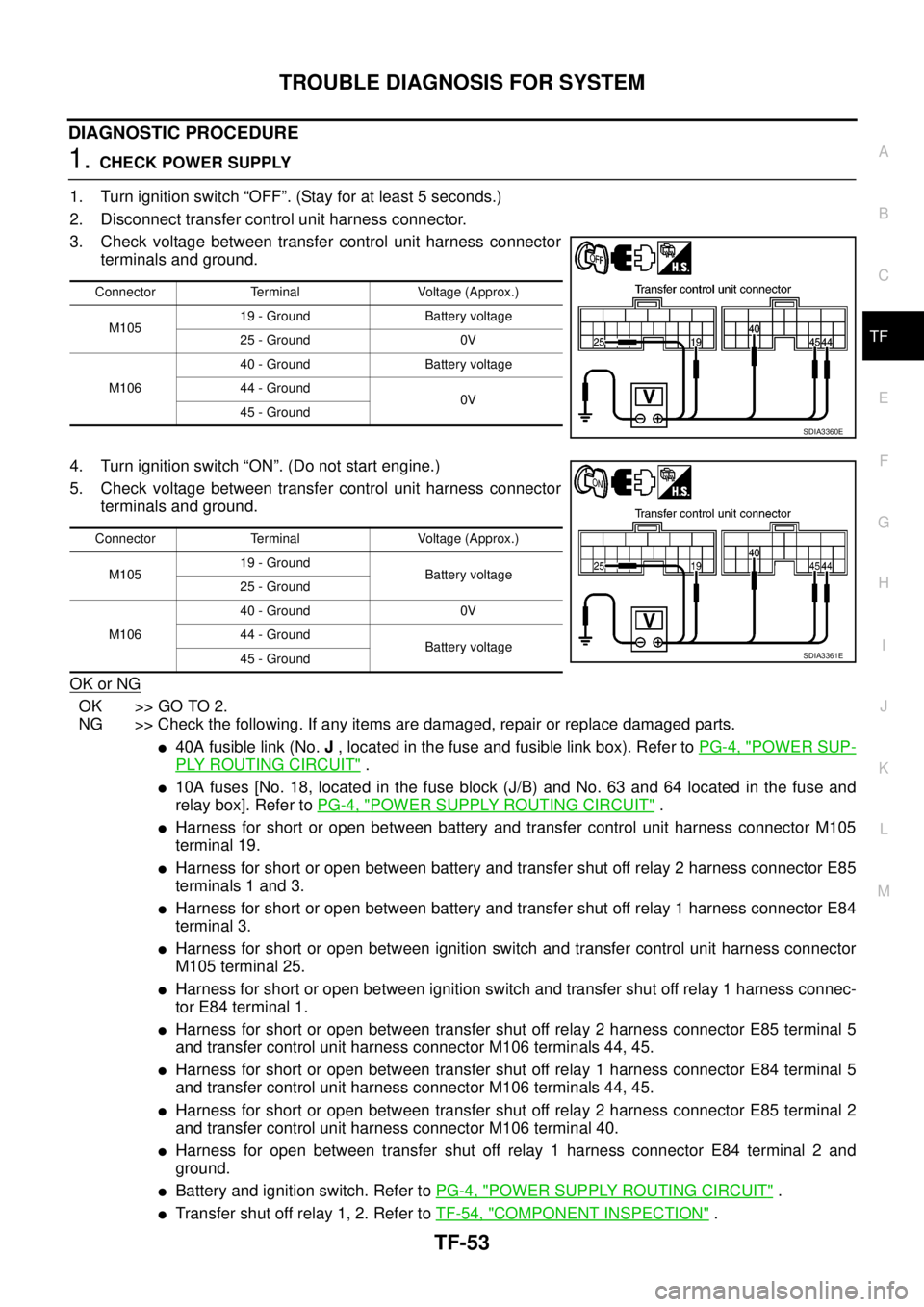
1.CHECK POWER SUPPLY
1. Turn ignition switch “OFF”. (Stay for at least 5 seconds.)
2. Disconnect transfer control unit harness connector.
3. Check voltage between transfer control unit harness connector
terminals and ground.
4. Turn ignition switch “ON”. (Do not start engine.)
5. Check voltage between transfer control unit harness connector
terminals and ground.
OK or NG
OK >> GO TO 2.
NG >> Check the following. If any items are damaged, repair or replace damaged parts.
l40A fusible link (No.J, located in the fuse and fusible link box). Refer toPG-4, "POWER SUP-
PLY ROUTING CIRCUIT".
l10A fuses [No. 18, located in the fuse block (J/B) and No. 63 and 64 located in the fuse and
relay box]. Refer toPG-4, "
POWER SUPPLY ROUTING CIRCUIT".
lHarness for short or open between battery and transfer control unit harness connector M105
terminal 19.
lHarness for short or open between battery and transfer shut off relay 2 harness connector E85
terminals 1 and 3.
lHarness for short or open between battery and transfer shut off relay 1 harness connector E84
terminal 3.
lHarness for short or open between ignition switch and transfer control unit harness connector
M105 terminal 25.
lHarness for short or open between ignition switch and transfer shut off relay 1 harness connec-
tor E84 terminal 1.
lHarness for short or open between transfer shut off relay 2 harness connector E85 terminal 5
and transfer control unit harness connector M106 terminals 44, 45.
lHarness for short or open between transfer shut off relay 1 harness connector E84 terminal 5
and transfer control unit harness connector M106 terminals 44, 45.
lHarness for short or open between transfer shut off relay 2 harness connector E85 terminal 2
and transfer control unit harness connector M106 terminal 40.
lHarness for open between transfer shut off relay 1 harness connector E84 terminal 2 and
ground.
lBattery and ignition switch. Refer toPG-4, "POWER SUPPLY ROUTING CIRCUIT".
lTransfer shut off relay 1, 2. Refer toTF-54, "COMPONENT INSPECTION".
Connector Terminal Voltage (Approx.)
M10519 - Ground Battery voltage
25 - Ground 0V
M10640 - Ground Battery voltage
44 - Ground
0V
45 - Ground
SDIA3360E
Connector Terminal Voltage (Approx.)
M10519 - Ground
Battery voltage
25 - Ground
M10640 - Ground 0V
44 - Ground
Battery voltage
45 - Ground
SDIA3361E