Page 2823 of 3171

SB-6
SEAT BELTS
REMOVALOFSEATBELTRETRACTOR
CAUTION:
lBefore servicing SRS, turn the ignition switch off, disconnect both battery cables and wait at least
3 minutes.
1. Remove the center pillar upper/lower finishers. Refer toEI-33, "
BODY SIDE TRIM".
2. Remove the seat belt retractor and belt bolts and assembly.
lOn RH side, disconnect the seat belt tension sensor.
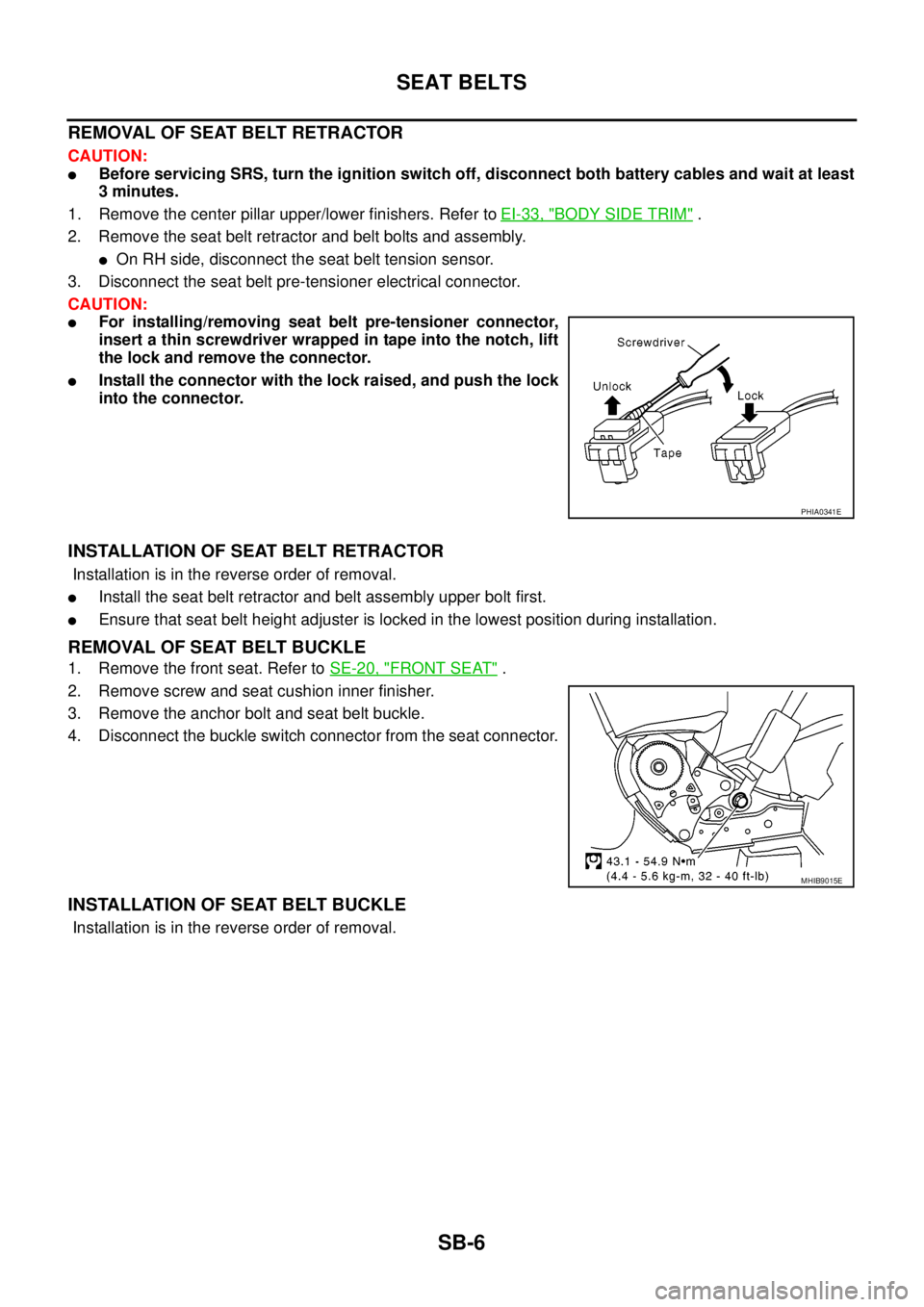
3. Disconnect the seat belt pre-tensioner electrical connector.
CAUTION:
lFor installing/removing seat belt pre-tensioner connector,
insert a thin screwdriver wrapped in tape into the notch, lift
the lock and remove the connector.
lInstall the connector with the lock raised, and push the lock
into the connector.
INSTALLATION OF SEAT BELT RETRACTOR
Installation is in the reverse order of removal.
lInstall the seat belt retractor and belt assembly upper bolt first.
lEnsure that seat belt height adjuster is locked in the lowest position during installation.
REMOVAL OF SEAT BELT BUCKLE
1. Remove the front seat. Refer toSE-20, "FRONT SEAT".
2. Remove screw and seat cushion inner finisher.
3. Remove the anchor bolt and seat belt buckle.
4. Disconnect the buckle switch connector from the seat connector.
INSTALLATION OF SEAT BELT BUCKLE
Installation is in the reverse order of removal.
PHIA0341E
MHIB9015E
Page 2829 of 3171

SB-12
SEAT BELTS
SEAT BELT RETRACTOR ON-VEHICLE CHECK
Emergency Locking Retractors (ELR)
NOTE:
All seat belt retractors are of the Emergency Locking Retractors (ELR) type. In an emergency (sudden stop)
the retractor will lock and prevent the belt from extending any further.
Check the seat belt retractors using the following test(s) to determine if a retractor assembly is operating prop-
erly.
ELR Function Stationary Check
Grasp the shoulder belt and pull forward quickly. The retractor should lock and prevent the belt from extending
further.
ELR Function Moving Check
WARNING:
Perform the following test in a safe, open area clear of other vehicles and obstructions (for example, a
large, empty parking lot). Road surface must be paved and dry. DO NOT perform the following test on
wet or gravel roads or on public streets and highways. This could result in an accident and serious
personal injury. The driver and passenger must be prepared to brace themselves in the event the
retractor does not lock.
1. Fasten drivers seat belt. Buckle a passenger into the seat for the belt that is to be tested.
2. Proceed to the designated safe area.
3. Drive the vehicle at approximately 16 km/h (10 MPH). Notify any passengers of a pending sudden stop.
The driver and passenger must be prepared to brace themselves in the event the retractor does not lock.
Apply brakes firmly and make a very hard stop.
During stop, seat belts should lock and not be extended. If the seat belt retractor assembly does not lock, per-
form the retractor off-vehicle check.
SEAT BELT RETRACTOR OFF-VEHICLE CHECK
1. Remove the seat belt retractor assembly.
2. Slowly pull out belt while tilting the retractor assembly forward from the mounted position without twisting
the retractor assembly as shown in the illustration.
Page 2830 of 3171
SEAT BELTS
SB-13
C
D
E
F
G
I
J
K
L
MA
B
SB
If NG, replace the retractor assembly.15 degrees or less tilt : Belt can be pulled out.
35 degrees or more tilt : Belt locks and cannot be pulled out.
PHIA0257E
Page 2847 of 3171

SC-14
CHARGING SYSTEM
CHARGING SYSTEM
PFP:00011
System DescriptionEKS00MZA
The alternator provides DC voltage to operate the vehicle's electrical system and to keep the battery charged.
The voltage output is controlled by the IC regulator.
Power is supplied at all times to alternator terminal 4 through:
l15A fuse (No. 30, located in the fuse and fusible link box).
Terminal 1 supplies power to charge the battery and operate the vehicle's electrical system. Output voltage is
controlled by the IC regulator at terminal 4 detecting the input voltage. The charging circuit is protected by the
140A fusible link (letter "A", located in the fuse and fusible link box) .
The alternator is grounded to the engine block.
With the ignition switch in the ON or START position, power is supplied
l10A fuse [No. 14, located in the fuse block (J/B)]
lto combination meter terminal 16 for the charge warning lamp.
Ground is supplied With power and ground supplied
lto terminal 2 of the combination meter
lthrough terminal 3 of the alternator.
If the charge warning lamp illuminates with the engine running, a fault is indicated.
The charge warning lamp will illuminate. When the alternator is providing sufficient voltage with the engine
running, the ground is opened and the charge warning lamp will go off.
Page 2854 of 3171

CHARGING SYSTEM
SC-21
C
D
E
F
G
H
I
J
L
MA
B
SC
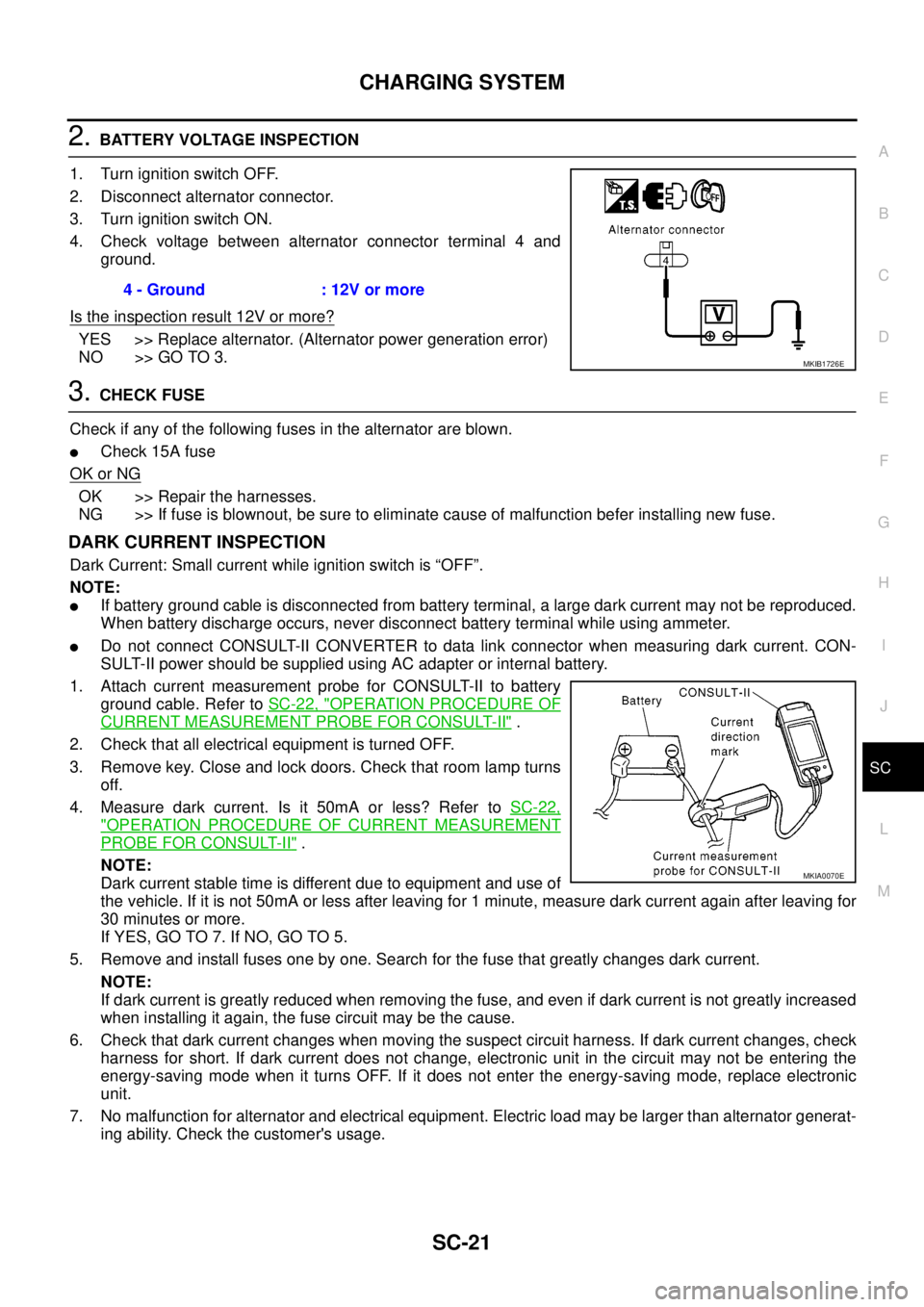
2.BATTERY VOLTAGE INSPECTION
1. Turn ignition switch OFF.
2. Disconnect alternator connector.
3. Turn ignition switch ON.
4. Check voltage between alternator connector terminal 4 and
ground.
Is the inspection result 12V or more?
YES >> Replace alternator. (Alternator power generation error)
NO >> GO TO 3.
3.CHECK FUSE
Check if any of the following fuses in the alternator are blown.
lCheck 15A fuse
OK or NG
OK >> Repair the harnesses.
NG >> If fuse is blownout, be sure to eliminate cause of malfunction befer installing new fuse.
DARK CURRENT INSPECTION
Dark Current: Small current while ignition switch is “OFF”.
NOTE:
lIf battery ground cable is disconnected from battery terminal, a large dark current may not be reproduced.
When battery discharge occurs, never disconnect battery terminal while using ammeter.
lDo not connect CONSULT-II CONVERTER to data link connector when measuring dark current. CON-
SULT-II power should be supplied using AC adapter or internal battery.
1. Attach current measurement probe for CONSULT-II to battery
ground cable. Refer toSC-22, "
OPERATION PROCEDURE OF
CURRENT MEASUREMENT PROBE FOR CONSULT-II".
2. Check that all electrical equipment is turned OFF.
3. Remove key. Close and lock doors. Check that room lamp turns
off.
4. Measure dark current. Is it 50mA or less? Refer toSC-22,
"OPERATION PROCEDURE OF CURRENT MEASUREMENT
PROBE FOR CONSULT-II".
NOTE:
Dark current stable time is different due to equipment and use of
the vehicle. If it is not 50mA or less after leaving for 1 minute, measure dark current again after leaving for
30 minutes or more.
If YES, GO TO 7. If NO, GO TO 5.
5. Remove and install fuses one by one. Search for the fuse that greatly changes dark current.
NOTE:
If dark current is greatly reduced when removing the fuse, and even if dark current is not greatly increased
when installing it again, the fuse circuit may be the cause.
6. Check that dark current changes when moving the suspect circuit harness. If dark current changes, check
harness for short. If dark current does not change, electronic unit in the circuit may not be entering the
energy-saving mode when it turns OFF. If it does not enter the energy-saving mode, replace electronic
unit.
7. No malfunction for alternator and electrical equipment. Electric load may be larger than alternator generat-
ing ability. Check the customer's usage.4 - Ground : 12V or more
MKIB1726E
MKIA0070E
Page 2857 of 3171
SC-24
CHARGING SYSTEM
RHD MODELS
DisassemblyEKS00MZG
REAR COVER
CAUTION:
Rear cover may be hard to remove because a ring is used to lock outer race of rear bearing. To facili-
tate removal of rear cover, heat just bearing box section with a 200W soldering iron.
Do not use a heat gun, as it can damage diode assembly.
REAR BEARING
CAUTION:
lDo not reuse rear bearing after removal. Replace with a new one.
lDo not lubricate rear bearing outer race.
1. Rear bearing 2. Rotor 3. Retainer
4. Front bearing 5. Through bolt 6. Front cover
7. Washer 8. Pulley 9. Stator
10. IC voltage regulator assembly 11. Diode assembly 12. Rear cover
13. B terminal
MKIB2001E
SEL032Z
Page 2858 of 3171
CHARGING SYSTEM
SC-25
C
D
E
F
G
H
I
J
L
MA
B
SC
InspectionEKS00MZH
ROTOR CHECK
1. Resistance test
lNot within the specified values... Replace rotor.
2. Insulator test
lContinuity exists... Replace rotor.
3. Check slip ring for wear.
lNot within the specified values... Replace rotor.
BRUSH CHECK
1. Check smooth movement of brush.
lNot smooth... Check brush holder and clean.
2. Check brush for wear.
lReplace brush if it is worn down to the limit line.
PULLEY CHECK (WITH CLUTCH TYPE)
1. Check for locking (Outer ring is turned counterclockwise when
viewed from the rear).
lIf it rotates in both directions... Replace pulley.
2. Check for dragging (Outer ring is turned clockwise when viewed
from the rear).
lIf it locks or unusual resistance is felt... Replace pulley.
STATOR CHECK
1. Continuity test
lNo continuity... Replace stator.Resistance : Refer to SDS.SC-37,
"Alternator"
Slip ring minimum
outer diameter: Refer to SDS.SC-37,
"Alternator"SEL033Z
SEL631DA
PKIA0458E
SEL108E
Page 2860 of 3171

STARTING SYSTEM
SC-27
C
D
E
F
G
H
I
J
L
MA
B
SC
STARTING SYSTEMPFP:00011
System DescriptionEKS00MZJ
A/T MODELS
Power is supplied at all times:
lto starter motor terminal 1 and
lthrough 40A fusible link (letterJ, located in the fuse and fusible link box)
lto ignition switch terminal 1.
with the ignition switch in the START position, power is supplied:
lfrom ignition switch terminal 5
lto IPDM E/R terminal 21.
With the ignition switch in the ON or START position, power is supplied to IPDM E/R CPU, and
the selector lever in the P or N position, power is supplied:
lthrough A/T assembly terminal 9
lto IPDM E/R terminal 48.
Ground is supplied at all times:
lto IPDM E/R terminals 38 and 59
lfrom body grounds E21, E41 and E61.
Then the starter relay is turned ON.
The IPDM E/R starter relay is energized and power is supplied:
lfrom terminal 19 of IPDM E/R
lto terminal 2 of the starter motor.
The starter motor plunger closes and provides a closed circuit between the battery and the starter motor. The
starter motor is grounded to the cylinder block. With power and ground supplied, the starter motor operates.
M/T MODELS
Power is supplied at all times:
lto starter motor terminal 1 and
lthrough 40A fusible link (letterJ, located in the fuse and fusible link box)
lto ignition switch terminal 1.
with the ignition switch in the START position, power is supplied:
lfrom ignition switch terminal 5
lto IPDM E/R terminal 21.
With the start signal is input to IPDM E/R CPU, power is supplied:
lthrough IPDM E/R terminal 14
lto IPDM E/R terminal 48.
Ground is supplied at all times:
lto IPDM E/R terminals 38 and 59
lfrom body grounds E21, E41 and E61.
Then the starter relay is turned ON.
The IPDM E/R starter relay is energized and power is supplied:
lfrom terminal 19 of IPDM E/R
lto terminal 2 of the starter motor.
The starter motor plunger closes and provides a closed circuit between the battery and the starter motor. The
starter motor is grounded to the cylinder block. With power and ground supplied, the starter motor operates.