2005 NISSAN NAVARA Brc
[x] Cancel search: BrcPage 1168 of 3171
EC-188
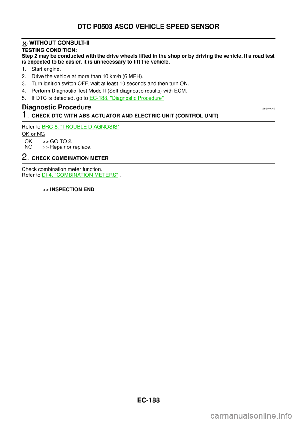
DTC P0503 ASCD VEHICLE SPEED SENSOR
WITHOUT CONSULT-II
TESTING CONDITION:
Step 2 may be conducted with the drive wheels lifted in the shop or by driving the vehicle. If a road test
is expected to be easier, it is unnecessary to lift the vehicle.
1. Start engine.
2. Drivethevehicleatmorethan10km/h(6MPH).
3. Turn ignition switch OFF, wait at least 10 seconds and then turn ON.
4. Perform Diagnostic Test Mode II (Self-diagnostic results) with ECM.
5. If DTC is detected, go toEC-188, "
Diagnostic Procedure".
Diagnostic ProcedureEBS01KHS
1.CHECK DTC WITH ABS ACTUATOR AND ELECTRIC UNIT (CONTROL UNIT)
Refer toBRC-8, "
TROUBLE DIAGNOSIS".
OK or NG
OK >> GO TO 2.
NG >> Repair or replace.
2.CHECK COMBINATION METER
Check combination meter function.
Refer toDI-4, "
COMBINATION METERS".
>>INSPECTION END
Page 1538 of 3171
FAX-6
WHEEL HUB
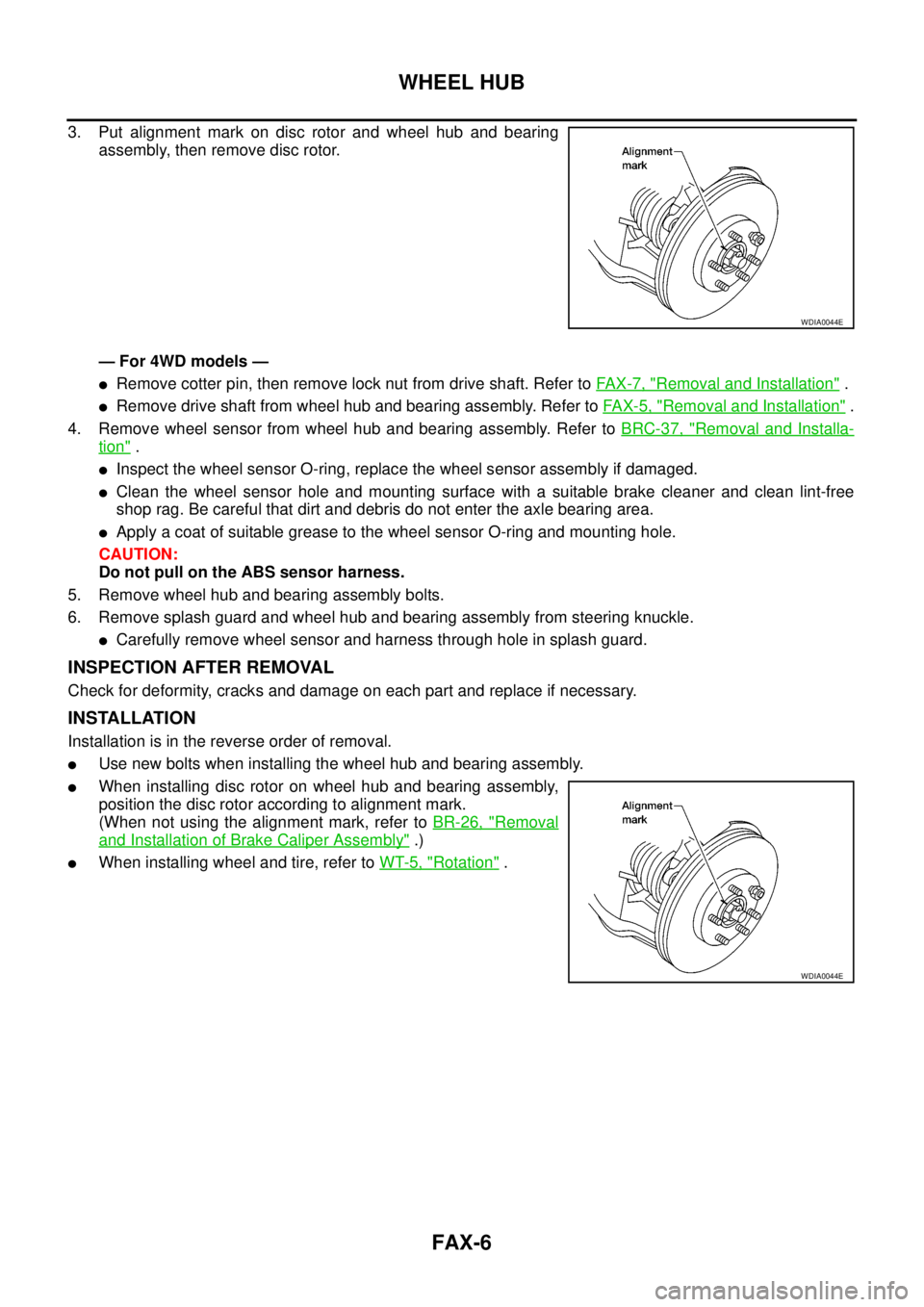
3. Put alignment mark on disc rotor and wheel hub and bearing
assembly, then remove disc rotor.
— For 4WD models —
lRemove cotter pin, then remove lock nut from drive shaft. Refer toFA X - 7 , "Removal and Installation".
lRemove drive shaft from wheel hub and bearing assembly. Refer toFAX-5, "Removal and Installation".
4. Remove wheel sensor from wheel hub and bearing assembly. Refer toBRC-37, "
Removal and Installa-
tion".
lInspect the wheel sensor O-ring, replace the wheel sensor assembly if damaged.
lClean the wheel sensor hole and mounting surface with a suitable brake cleaner and clean lint-free
shop rag. Be careful that dirt and debris do not enter the axle bearing area.
lApply a coat of suitable grease to the wheel sensor O-ring and mounting hole.
CAUTION:
Do not pull on the ABS sensor harness.
5. Remove wheel hub and bearing assembly bolts.
6. Remove splash guard and wheel hub and bearing assembly from steering knuckle.
lCarefully remove wheel sensor and harness through hole in splash guard.
INSPECTION AFTER REMOVAL
Check for deformity, cracks and damage on each part and replace if necessary.
INSTALLATION
Installation is in the reverse order of removal.
lUse new bolts when installing the wheel hub and bearing assembly.
lWhen installing disc rotor on wheel hub and bearing assembly,
position the disc rotor according to alignment mark.
(When not using the alignment mark, refer toBR-26, "
Removal
and Installation of Brake Caliper Assembly".)
lWhen installing wheel and tire, refer toWT-5, "Rotation".
WDIA0044E
WDIA0044E
Page 1754 of 3171
IDX-2
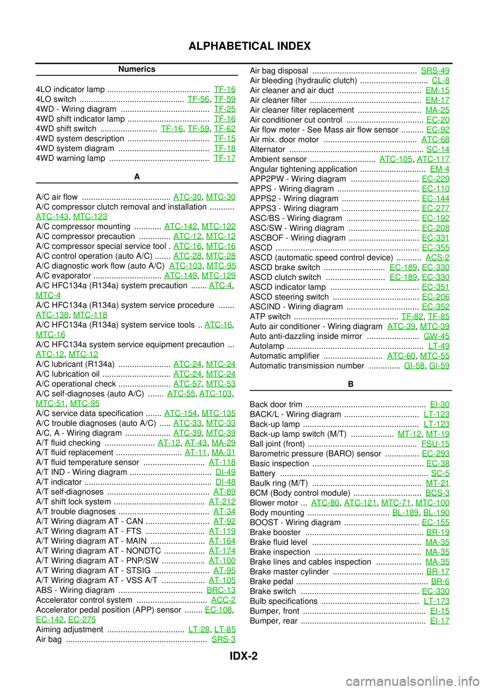
ALPHABETICAL INDEX
Numerics
4LO indicator lamp .............................................TF-16
4LO switch ..............................................TF-56,TF-59
4WD - Wiring diagram .......................................TF-25
4WD shift indicator lamp ....................................TF-16
4WD shift switch .........................TF-16,TF-59,TF-62
4WD system description ....................................TF-15
4WD system diagram ........................................TF-18
4WD warning lamp ............................................TF-17
A
A/C air flow .......................................ATC-30
,MTC-30
A/C compressor clutch removal and installation ...........
ATC-143
,MTC-123
A/C compressor mounting ............ATC-142,MTC-122
A/C compressor precaution ..............ATC-12,MTC-12
A/C compressor special service tool .ATC-16,MTC-16
A/C control operation (auto A/C) .......ATC-28,MTC-28
A/C diagnostic work flow (auto A/C)ATC-103,MTC-95
A/C evaporator ..............................ATC-149,MTC-129
A/C HFC134a (R134a) system precaution .......ATC-4,
MTC-4
A/C HFC134a (R134a) system service procedure .......
ATC-138
,MTC-118
A/C HFC134a (R134a) system service tools ..ATC-16,
MTC-16
A/C HFC134a system service equipment precaution ...
ATC-12
,MTC-12
A/C lubricant (R134a) .......................ATC-24,MTC-24
A/C lubrication oil ..............................ATC-24,MTC-24
A/C operational check .......................ATC-57,MTC-53
A/C self-diagnoses (auto A/C) .......ATC-55,ATC-103,
MTC-51
,MTC-95
A/C service data specification .......ATC-154,MTC-135
A/C trouble diagnoses (auto A/C) .....ATC-33,MTC-33
A/C, A - Wiring diagram ....................ATC-39,MTC-39
A/T fluid checking ......................AT-12,AT-43,MA-29
A/T fluid replacement .............................AT-11,MA-31
A/T fluid temperature sensor ...........................AT-118
A/T IND - Wiring diagram ....................................DI-49
A/T indicator ........................................................DI-48
A/T self-diagnoses .............................................AT-89
A/T shift lock system ........................................AT-212
A/T trouble diagnoses ........................................AT-34
A/T Wiring diagram AT - CAN ............................AT-92
A/T Wiring diagram AT - FTS ..........................AT-119
A/T Wiring diagram AT - MAIN ........................AT-164
A/T Wiring diagram AT - NONDTC ..................AT-174
A/T Wiring diagram AT - PNP/SW ...................AT-100
A/T Wiring diagram AT - STSIG ........................AT-95
A/T Wiring diagram AT - VSS A/T ...................AT-105
ABS - Wiring diagram .....................................BRC-13
Accelerator control system ...............................ACC-2
Accelerator pedal position (APP) sensor ........EC-108,
EC-142
,EC-275
Aiming adjustment ..................................LT-28,LT-85
Air bag ..............................................................SRS-3
Air bag disposal ..............................................SRS-49
Air bleeding (hydraulic clutch) ..............................CL-8
Air cleaner and air duct .....................................EM-15
Air cleaner filter .................................................EM-17
Air cleaner filter replacement ............................MA-25
Air conditioner cut control ..................................EC-20
Air flow meter - See Mass air flow sensor ..........EC-92
Air mix. door motor .........................................ATC-68
Alternator ...........................................................SC-14
Ambient sensor .............................ATC-105,ATC-117
Angular tightening application .............................EM-4
APP2PW - Wiring diagram ..............................EC-229
APPS - Wiring diagram ....................................EC-110
APPS2 - Wiring diagram ..................................EC-144
APPS3 - Wiring diagram ..................................EC-277
ASC/BS - Wiring diagram ................................EC-192
ASC/SW - Wiring diagram ...............................EC-208
ASCBOF - Wiring diagram ...............................EC-331
ASCD ...............................................................EC-355
ASCD (automatic speed control device) ...........ACS-2
ASCD brake switch ...........................EC-189,EC-330
ASCD clutch switch ..........................EC-189,EC-330
ASCD indicator lamp .......................................EC-351
ASCD steering switch ......................................EC-206
ASCIND - Wiring diagram ................................EC-352
ATP switch ..............................................TF-82,TF-85
Auto air conditioner - Wiring diagramATC-39,MTC-39
Auto anti-dazzling inside mirror .......................GW-45
Autolamp ............................................................LT-49
Automatic amplifier ..........................ATC-60,MTC-55
Automatic transmission number ..............GI-58,GI-59
B
Back door trim .....................................................EI-30
BACK/L - Wiring diagram .................................LT-123
Back-up lamp ...................................................LT-123
Back-up lamp switch (M/T) ...................MT-12,MT-19
Ball joint (front) ................................................FSU-15
Barometric pressure (BARO) sensor ...............EC-293
Basic inspection .................................................EC-38
Battery .................................................................SC-5
Baulk ring (M/T) ................................................MT-21
BCM (Body control module) ..............................BCS-3
Blower motor ...ATC-80,ATC-121,MTC-71,MTC-100
Body mounting ....................................BL-189,BL-190
BOOST - Wiring diagram .................................EC-155
Brake booster ....................................................BR-19
Brake fluid level ................................................MA-35
Brake inspection ...............................................MA-35
Brake lines and cables inspection ....................MA-35
Brake master cylinder ........................................BR-17
Brake pedal ..........................................................BR-6
Brake switch ....................................................EC-330
Bulb specifications ...........................................LT-173
Bumper, front ......................................................EI-15
Bumper, rear .......................................................EI-17
Page 1755 of 3171
IDX-3
A
C
D
E
F
G
H
I
J
K
L B
IDX
ALPHABETICAL INDEX
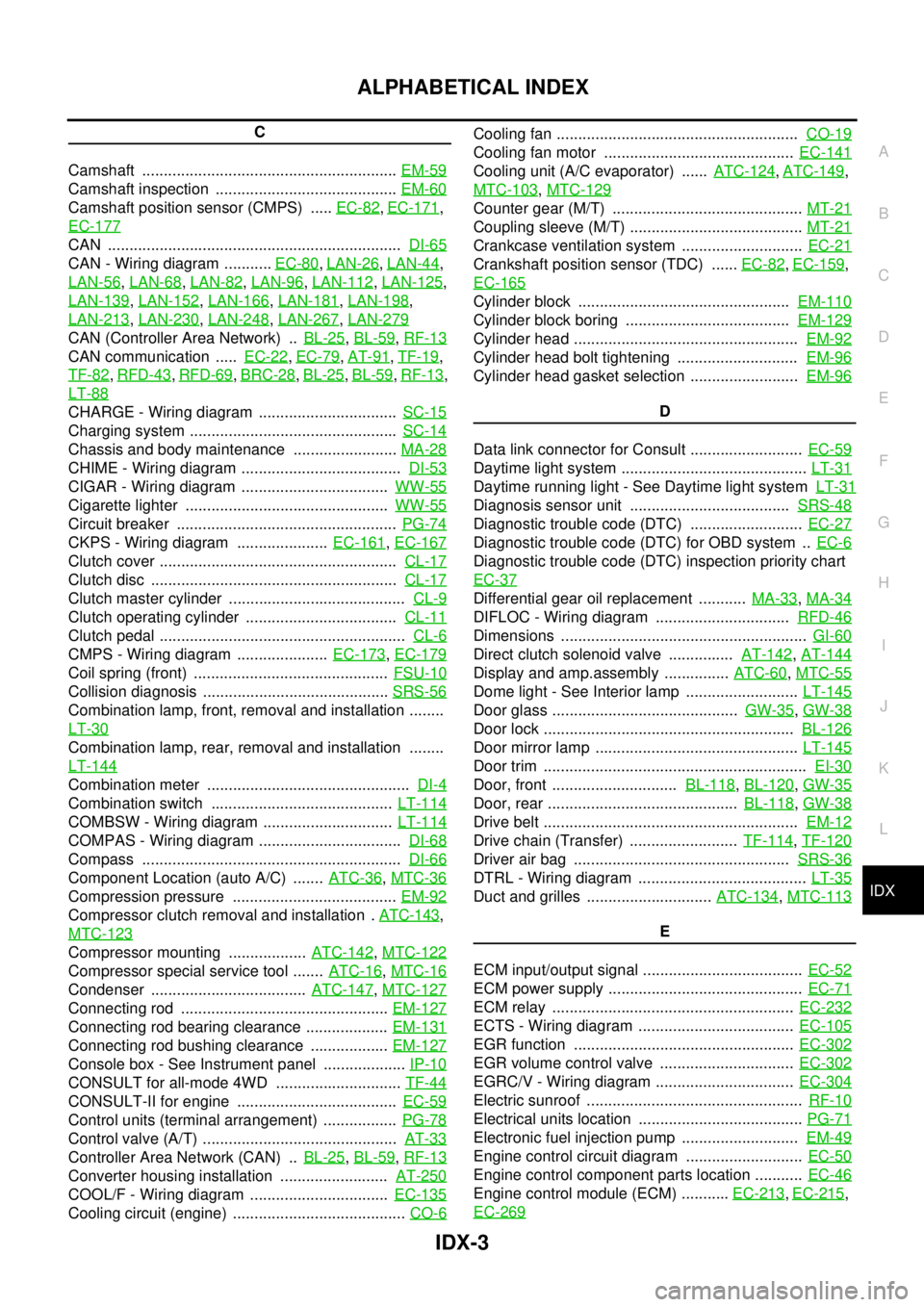
C
Camshaft ...........................................................EM-59
Camshaft inspection ..........................................EM-60
Camshaft position sensor (CMPS) .....EC-82,EC-171,
EC-177
CAN ....................................................................DI-65
CAN - Wiring diagram ...........EC-80,LAN-26,LAN-44,
LAN-56
,LAN-68,LAN-82,LAN-96,LAN-112,LAN-125,
LAN-139
,LAN-152,LAN-166,LAN-181,LAN-198,
LAN-213
,LAN-230,LAN-248,LAN-267,LAN-279
CAN (Controller Area Network) ..BL-25,BL-59,RF-13
CAN communication .....EC-22,EC-79,AT-91,TF-19,
TF-82
,RFD-43,RFD-69,BRC-28,BL-25,BL-59,RF-13,
LT-88
CHARGE - Wiring diagram ................................SC-15
Charging system ................................................SC-14
Chassis and body maintenance ........................MA-28
CHIME - Wiring diagram .....................................DI-53
CIGAR - Wiring diagram ..................................WW-55
Cigarette lighter ...............................................WW-55
Circuit breaker ...................................................PG-74
CKPS - Wiring diagram .....................EC-161,EC-167
Clutch cover .......................................................CL-17
Clutch disc .........................................................CL-17
Clutch master cylinder .........................................CL-9
Clutch operating cylinder ...................................CL-11
Clutch pedal .........................................................CL-6
CMPS - Wiring diagram .....................EC-173,EC-179
Coil spring (front) .............................................FSU-10
Collision diagnosis ...........................................SRS-56
Combination lamp, front, removal and installation ........
LT-30
Combination lamp, rear, removal and installation ........
LT-144
Combination meter ...............................................DI-4
Combination switch ..........................................LT-114
COMBSW - Wiring diagram ..............................LT-114
COMPAS - Wiring diagram .................................DI-68
Compass ............................................................DI-66
Component Location (auto A/C) .......ATC-36,MTC-36
Compression pressure ......................................EM-92
Compressor clutch removal and installation .ATC-143,
MTC-123
Compressor mounting ..................ATC-142,MTC-122
Compressor special service tool .......ATC-16,MTC-16
Condenser ....................................ATC-147,MTC-127
Connecting rod ................................................EM-127
Connecting rod bearing clearance ...................EM-131
Connecting rod bushing clearance ..................EM-127
Console box - See Instrument panel ...................IP-10
CONSULT for all-mode 4WD .............................TF-44
CONSULT-II for engine .....................................EC-59
Control units (terminal arrangement) .................PG-78
Control valve (A/T) .............................................AT-33
Controller Area Network (CAN) ..BL-25,BL-59,RF-13
Converter housing installation .........................AT-250
COOL/F - Wiring diagram ................................EC-135
Cooling circuit (engine) ........................................CO-6
Cooling fan ........................................................CO-19
Cooling fan motor ............................................EC-141
Cooling unit (A/C evaporator) ......ATC-124,ATC-149,
MTC-103
,MTC-129
Counter gear (M/T) ............................................MT-21
Coupling sleeve (M/T) ........................................MT-21
Crankcase ventilation system ............................EC-21
Crankshaft position sensor (TDC) ......EC-82,EC-159,
EC-165
Cylinder block .................................................EM-110
Cylinder block boring ......................................EM-129
Cylinder head ....................................................EM-92
Cylinder head bolt tightening ............................EM-96
Cylinder head gasket selection .........................EM-96
D
Data link connector for Consult ..........................EC-59
Daytime light system ...........................................LT-31
Daytime running light - See Daytime light systemLT-31
Diagnosis sensor unit .....................................SRS-48
Diagnostic trouble code (DTC) ..........................EC-27
Diagnostic trouble code (DTC) for OBD system ..EC-6
Diagnostic trouble code (DTC) inspection priority chart
EC-37
Differential gear oil replacement ...........MA-33,MA-34
DIFLOC - Wiring diagram ...............................RFD-46
Dimensions .........................................................GI-60
Direct clutch solenoid valve ...............AT-142,AT-144
Display and amp.assembly ...............ATC-60,MTC-55
Dome light - See Interior lamp ..........................LT-145
Door glass ...........................................GW-35,GW-38
Door lock ..........................................................BL-126
Door mirror lamp ...............................................LT-145
Door trim .............................................................EI-30
Door, front .............................BL-118,BL-120,GW-35
Door, rear ............................................BL-118,GW-38
Drive belt ...........................................................EM-12
Drive chain (Transfer) .........................TF-114,TF-120
Driver air bag ..................................................SRS-36
DTRL - Wiring diagram .......................................LT-35
Duct and grilles .............................ATC-134,MTC-113
E
ECM input/output signal .....................................EC-52
ECM power supply .............................................EC-71
ECM relay ........................................................EC-232
ECTS - Wiring diagram ....................................EC-105
EGR function ...................................................EC-302
EGR volume control valve ...............................EC-302
EGRC/V - Wiring diagram ................................EC-304
Electric sunroof ..................................................RF-10
Electrical units location ......................................PG-71
Electronic fuel injection pump ...........................EM-49
Engine control circuit diagram ...........................EC-50
Engine control component parts location ...........EC-46
Engine control module (ECM) ...........EC-213,EC-215,
EC-269
Page 1759 of 3171
IDX-7
A
C
D
E
F
G
H
I
J
K
L B
IDX
ALPHABETICAL INDEX
Starter ................................................................SC-27
Starting system ..................................................SC-27
Steering gear, linkage and transfer gear inspection .....
MA-36
,MA-37
Steering linkage .................................................PS-14
Steering wheel and column .................................PS-8
Step lamp .........................................................LT-145
Stop lamp .........................................................LT-121
Stop lamp switch .............................................EC-330
STOP/L - Wiring diagram .................................LT-121
Striking rod (M/T) ...............................................MT-23
Strut (front) ......................................................FSU-10
Sun roof, electric ................................................RF-10
Sunload sensor ..............................................ATC-112
Sunroof ..................................................RF-10,RF-21
Super lock ...........................................................BL-55
Supplemental Restraint System ........................SRS-6
Symbols and abbreviations .....................GI-10,GI-23
Symptom matrix chart ........................................EC-42
Synchronizer (M/T) ............................................MT-21
T
Tachometer ..........................................................DI-4
Tail lamp ...........................................................LT-125
TAIL/L - Wiring diagram ....................................LT-127
TC boost control solnoid valve ........................EC-309
TC boost sensor ..............................................EC-153
TCC/V - Wiring diagram ..................................EC-311
TCM circuit diagram ..........................................AT-42
TCM inspection table .........................................AT-76
Thermostat ........................................................CO-24
Three way catalyst precautions ............................GI-5
Throttle body ......................................................EM-20
Tie-rod ...............................................................PS-14
Timing chain .........................................EM-73,EM-79
Timing gear ........................................................EM-79
Tire rotation .......................................................MA-34
Tire size ..............................................................GI-60
Torque converter installation ...........................AT-250
Torque convertor clutch solenoid valveAT-110,AT-112
Tow truck towing .................................................GI-53
Towing point .......................................................GI-54
Transfer control device .............TF-74,TF-78,TF-105
Transfer control unit inspection table ..................TF-38
Transfer oil replacement ....................................MA-32
Transfer serial number .......................................GI-58
Transmission case (M/T) ...................................MT-19
Transmission serial number ....................GI-58,GI-59
Tread-FR&RR (Dimensions) ..............................GI-60
Trim .....................................................................EI-33
Trouble diagnoses ..............................................GI-11
Turbine revolution sensor ................................AT-123
Turbocharger .....................................................EM-28
Turbocharger charge air cooler .........................EM-18
Turbocharger precautions ....................................GI-6
TURN - Wiring diagram ....................................LT-100
Turn signal lamp .................................................LT-97
Two-pole lift ........................................................GI-52
V
Vacuum hose drawing (Engine control) .............EC-16
Vacuum pump ...................................................EM-42
Valve clearance ................................................EM-66
Valve guide .....................................................EM-101
Valve lifter .........................................................EM-62
Valve seat .......................................................EM-103
Valve spring ....................................................EM-104
Vanity mirror lamp .............................................LT-145
Vehicle identification number ..............................GI-57
Vehicle recovery (freeing a stuck vehicle) ..........GI-54
VEHSEC - Wiring diagram ...............................BL-143
Viscosity number (SAE) ....................................MA-15
W
Wait detection switch ..............................TF-63
,TF-66
WARN - Wiring diagram .....................................DI-30
Warning chime ....................................................DI-51
Warning lamps ....................................................DI-28
Washer, front .....................................................WW-4
Water pump ......................................................CO-21
Water temperature gauge .....................................DI-4
Wheel alignment (front) .....................................FSU-7
Wheel balance ..................................................MA-34
Wheel bearing (front) .........................................FAX-5
Wheel bearing (rear) .........................................RAX-6
Wheel sensors (ABS) .....................................BRC-37
Wheel size ..........................................................GI-60
Wheelbase (Dimensions) ....................................GI-60
Width (Dimensions) ............................................GI-60
WINDOW - Wiring diagram ...............................GW-20
Window, door ......................................GW-35,GW-38
Window, rear .....................................................GW-43
Windshield ........................................................GW-11
WIPER - Wiring diagram ..................................WW-12
Wiper, front ........................................................WW-4
Wiring Diagram (Cell code) list ..........................PG-68
Wiring diagrams ..................................................GI-15
Page 2597 of 3171

PG-68
HARNESS
Wiring Diagram Codes (Cell Codes)
EKS00LJ9
Use the chart below to find out what each wiring diagram code stands for.
Refer to the wiring diagram code in the alphabetical index to find the location (page number) of each wiring
diagram.
Code Section Wiring Diagram Name
A/C,A ATC Auto Air Conditioner
A/C,M MTC Manual Air Conditioner
ABS BRC Anti-lock Brake System
APP1PW EC Accelerator Pedal Position Sensor 1 Power
APP2PW EC Accelerator Pedal Position Sensor 2 Power
APPS1 EC Accelerator Pedal Position Sensor 1
APPS2 EC Accelerator Pedal Position Sensor 2
APPS3 EC Accelerator Pedal Position Sensor
ASC/BS EC ASCD Brake Switch
ASC/SW EC ASCD Steering Switch
ASCBOF EC ASCD Brake Switch
ASCIND EC ASCD Indicator
AT/IND DI A/T Indicator Lamp
AUDIO AV Audio
AUTO/L LT Auto Lignt System
BACK/L LT Back-up Lamp
BOOST EC Turbocharger Boost Sensor
CAN AT CAN Communication Line
CAN EC CAN Communication Line
CAN LAN CAN System
CHARGE SC Charging System
CHIME DI Warning Chime
CIGER WW Cigarette Lighter
CKPS EC Crankshaft Position Sensor
CMPS EC Camshaft Position Sensor
COMBSW LT Combination Switch
COMM AV Audio Visual Communication Line
COMPAS DI Compass
COOL/F EC Cooling Fan Control
D/LOCK BL Power Door Lock
DIFLOC RFD Rear Final Drive
DEF GW Rear Window Defogger
DTRL LT Headlamp — With Daytime Running Light System
ECMRLY EC ECM Relay
ECTS EC Engine Coolant Temperature Sensor
EGRVLV EC EGR Volume Control System
EMNT EC Electronic Controlled Engine Mount Control Solenoid Valve
F/FOG LT Front Fog Lamp
F/PUMP EC Fuel Pump
FRPS EC Fuel Rail Pressure Sensor
FTS AT A/T Fluid Temperature Sensor
Page 2672 of 3171
![NISSAN NAVARA 2005 Repair Workshop Manual AXLE SHAFT
RAX-9
[M226]
C
E
F
G
H
I
J
K
L
MA
B
RAX
INSPECTION AFTER REMOVAL
Axle Shaft Bearing and Cup
lCheck that the axle shaft bearing and cup roll freely and are free from noise, cracks, pitting a NISSAN NAVARA 2005 Repair Workshop Manual AXLE SHAFT
RAX-9
[M226]
C
E
F
G
H
I
J
K
L
MA
B
RAX
INSPECTION AFTER REMOVAL
Axle Shaft Bearing and Cup
lCheck that the axle shaft bearing and cup roll freely and are free from noise, cracks, pitting a](/manual-img/5/57362/w960_57362-2671.png)
AXLE SHAFT
RAX-9
[M226]
C
E
F
G
H
I
J
K
L
MA
B
RAX
INSPECTION AFTER REMOVAL
Axle Shaft Bearing and Cup
lCheck that the axle shaft bearing and cup roll freely and are free from noise, cracks, pitting and wear.
Replace if necessary.
Axle Shaft Retainer
lCheck for deformation and cracks. Replace if necessary.
Rear Axle Case
lCheck the exterior and inner machined surfaces for deformation and cracks. Replace if necessary.
INSTALLATION
Installation is in the reverse order of removal.
When installing pay attention to following points:
lInstall a new shaft guide and a new oil seal into the rear axle case.
CAUTION:
lDo not reuse the axle oil seal. The axle oil seal must be replaced every time the axle shaft assem-
bly is removed from the axle shaft housing.
lWhen installing oil seals, apply multi-purpsose grease to oil seal lips.
lInstall four new lock nuts to secure the axle shaft assembly to the rear axle case, and tighten lock nuts to
the specified torque. Refer toRAX-7, "
Removal and Installation".
lReinstall the rear brake drum. Refer toBR-31, "Removal and Installation of Drum Brake Assembly".
lAdjust the differential gear oil level.
Refer toRFD-9, "
DIFFERENTIAL GEAR OIL", for M226 without LD.
Refer toRFD-9, "
DIFFERENTIAL GEAR OIL", for M226 with LD.
lReinstall the wheel. Refer toWT-5, "Rotation".
DISASSEMBLY
1. Remove the ABS sensor rotor. Refer toBRC-39, "SENSOR ROTOR".
2. Remove the snap ring from the axle shaft using a suitable snap ring pliers.
3. Secure the axle shaft in a suitable vise as shown, and use a
brass hammer to remove studs (4) from the axle shaft retainer.
CAUTION:
lMount the axle shaft using a soft jaw vise to avoid dam-
aging the axle shaft retainer.
MDIB9051E
Page 2674 of 3171
![NISSAN NAVARA 2005 Repair Workshop Manual AXLE SHAFT
RAX-11
[M226]
C
E
F
G
H
I
J
K
L
MA
B
RAX
INSPECTION AFTER DISASSEMBLY
Axle Shaft
lClean and remove all nicks and burrs.
lCheck for straightness and distortion. Replace if necessary.
lInspec NISSAN NAVARA 2005 Repair Workshop Manual AXLE SHAFT
RAX-11
[M226]
C
E
F
G
H
I
J
K
L
MA
B
RAX
INSPECTION AFTER DISASSEMBLY
Axle Shaft
lClean and remove all nicks and burrs.
lCheck for straightness and distortion. Replace if necessary.
lInspec](/manual-img/5/57362/w960_57362-2673.png)
AXLE SHAFT
RAX-11
[M226]
C
E
F
G
H
I
J
K
L
MA
B
RAX
INSPECTION AFTER DISASSEMBLY
Axle Shaft
lClean and remove all nicks and burrs.
lCheck for straightness and distortion. Replace if necessary.
lInspect machined surfaces for evidence of overheating, damage and wear. Replace if necessary.
lMeasure the bearing ring retainer axle journal diameter. Replace if necessary.
ASSEMBLY
1. Install a new grease catcher onto the axle shaft.
2. Reinstall studs on the axle shaft retainer, and install the axle shaft retainer on the axle shaft.
3. Install a new seal lip onto the axle shaft.
CAUTION:
lSeal lip can not be reused. Do not attempt to reuse it.
lWhen installing oil seals, apply multi-purpose grease to oil seal lips.
4. Install a new bearing on the axle shaft.
CAUTION:
lWheel bearing can not be reused. Do not attempt to reuse it.
5. Using a bearing inserter, and a suitable press, press fit the axle
shaft to the new bearing ring retainer, until the snap ring groove.
CAUTION:
lMake sure the bearing ring retainer, axle shaft bearing,
axle shaft lip seal, and axle shaft retainer are installed
facing in the correct direction.
lBearing ring retainer can not be reused. Do not attempt to
reuse it.
6. Apply grease to the bearing cup, and install onto the axle shaft
bearing.
7. Install a new snap ring using a suitable snap ring pliers.
CAUTION:
Discard the old snap ring: replace with new ones.
8. Install the new ABS rotor sensor. Refer toBRC-39, "
SENSOR ROTOR".
CAUTION:
Discard the old sensor rotor; replace with a new one.Bearing ring retainer axle journal diameter (minimum)
: 45.027 mm (1.7727 in)
MDIB9047E