Page 2771 of 3171
![NISSAN NAVARA 2005 Repair Workshop Manual RFD-68
[WITH ELECTRONIC LOCKING DIFFERENTIAL]
TROUBLE DIAGNOSIS FOR SYSTEM
COMPONENT INSPECTION
1. Turn ignition switch “OFF”.
2. Disconnect differential lock solenoid harness connector.
3. Check NISSAN NAVARA 2005 Repair Workshop Manual RFD-68
[WITH ELECTRONIC LOCKING DIFFERENTIAL]
TROUBLE DIAGNOSIS FOR SYSTEM
COMPONENT INSPECTION
1. Turn ignition switch “OFF”.
2. Disconnect differential lock solenoid harness connector.
3. Check](/manual-img/5/57362/w960_57362-2770.png)
RFD-68
[WITH ELECTRONIC LOCKING DIFFERENTIAL]
TROUBLE DIAGNOSIS FOR SYSTEM
COMPONENT INSPECTION
1. Turn ignition switch “OFF”.
2. Disconnect differential lock solenoid harness connector.
3. Check resistance between differential lock solenoid harness
connector C23 terminals 1 and 2.
4. If NG, replace differential lock solenoid. Refer toRFD-86, "
Differ-
ential Assembly".
5. Check operation by applying battery voltage to differential lock
solenoid harness connector terminals.
CAUTION:
Be sure to apply the voltage of the correct polarity to the
respective terminals. Otherwise, the part may be damaged.
6. If NG, replace differential lock solenoid.
ABS SystemEDS003B7
DIAGNOSTIC PROCEDURE
1.CHECK DTC WITH ABS ACTUATOR AND ELECTRIC UNIT (CONTROL UNIT)
Perform self-diagnosis with ABS actuator and electric unit (control unit). Refer toBRC-18, "
Self-Diagnosis".
Is any malfunction detected by self-diagnosis?
YES >> Check the malfunctioning system.
NO >> GO TO 2.
2.CHECK DIFFERENTIAL LOCK CONTROL UNIT
Check differential lock control unit input/output signal. Refer toRFD-48, "
Differential Lock Control Unit Input/
Output Signal Reference Values".
OK or NG
OK >> GO TO 3.
NG >> Check differential lock control unit pin terminals for damage or loose connection with harness con-
nector. If any items are damaged, repair or replace damaged parts.
3.CHECK DTC
Perform the self-diagnosis, after driving the vehicle for a while.
OK or NG
OK >>INSPECTION END
NG >> Perform self-diagnosis with ABS actuator and electric unit (control unit) again. Refer toBRC-18,
"Self-Diagnosis". 1-2 :Approx.3.4W
SDIA3431E
Connector Terminal
C23 1 (Battery voltage) - 2 (Ground)
SDIA3432E
Page 3022 of 3171

TROUBLE DIAGNOSIS FOR SYSTEM
TF-55
C
E
F
G
H
I
J
K
L
MA
B
TF
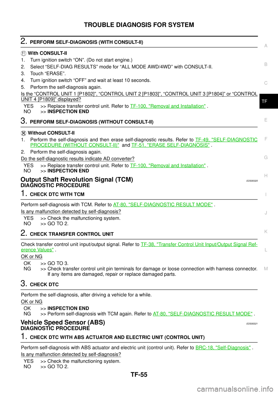
2.PERFORM SELF-DIAGNOSIS (WITH CONSULT-II)
With CONSULT-II
1. Turn ignition switch “ON”. (Do not start engine.)
2. Select “SELF-DIAG RESULTS” mode for “ALL MODE AWD/4WD” with CONSULT-II.
3. Touch “ERASE”.
4. Turn ignition switch “OFF” and wait at least 10 seconds.
5. Perform the self-diagnosis again.
Is the
“CONTROL UNIT 1 [P1802]”,“CONTROL UNIT 2 [P1803]”,“CONTROL UNIT 3 [P1804]”or“CONTROL
UNIT 4 [P1809]”displayed?
YES >> Replace transfer control unit. Refer toTF-100, "Removal and Installation".
NO >>INSPECTION END
3.PERFORM SELF-DIAGNOSIS (WITHOUT CONSULT-II)
Without CONSULT-II
1. Perform the self-diagnosis and then erase self-diagnostic results. Refer toTF-49, "
SELF-DIAGNOSTIC
PROCEDURE (WITHOUT CONSULT-II)"andTF-51, "ERASE SELF-DIAGNOSIS".
2. Perform the self-diagnosis again.
Do the self-diagnostic results indicate AD converter?
YES >> Replace transfer control unit. Refer toTF-100, "Removal and Installation".
NO >>INSPECTION END
Output Shaft Revolution Signal (TCM)EDS00320
DIAGNOSTIC PROCEDURE
1.CHECK DTC WITH TCM
Perform self-diagnosis with TCM. Refer toAT-80, "
SELF-DIAGNOSTIC RESULT MODE".
Is any malfunction detected by self-diagnosis?
YES >> Check the malfunctioning system.
NO >> GO TO 2.
2.CHECK TRANSFER CONTROL UNIT
Check transfer control unit input/output signal. Refer toTF-38, "
Transfer Control Unit Input/Output Signal Ref-
erence Values".
OK or NG
OK >> GO TO 3.
NG >> Check transfer control unit pin terminals for damage or loose connection with harness connector.
If any items are damaged, repair or replace damaged parts.
3.CHECK DTC
Perform the self-diagnosis, after driving a vehicle for a while.
OK or NG
OK >>INSPECTION END
NG >> Perform self-diagnosis with TCM again. Refer toAT-80, "
SELF-DIAGNOSTIC RESULT MODE".
Vehicle Speed Sensor (ABS)EDS00321
DIAGNOSTIC PROCEDURE
1.CHECK DTC WITH ABS ACTUATOR AND ELECTRIC UNIT (CONTROL UNIT)
Perform self-diagnosis with ABS actuator and electric unit (control unit). Refer toBRC-18, "
Self-Diagnosis".
Is any malfunction detected by self-diagnosis?
YES >> Check the malfunctioning system.
NO >> GO TO 2.
Page 3023 of 3171

TF-56
TROUBLE DIAGNOSIS FOR SYSTEM
2.CHECK TRANSFER CONTROL UNIT
Check transfer control unit input/output signal. Refer toTF-38, "
Transfer Control Unit Input/Output Signal Ref-
erence Values".
OK or NG
OK >> GO TO 3.
NG >> Check transfer control unit pin terminals for damage or loose connection with harness connector.
If any items are damaged, repair or replace damaged parts.
3.CHECK DTC
Perform the self-diagnosis, after driving a vehicle for a while.
OK or NG
OK >>INSPECTION END
NG >> Perform self-diagnosis with ABS actuator and electric unit (control unit) again. Refer toBRC-18,
"Self-Diagnosis".
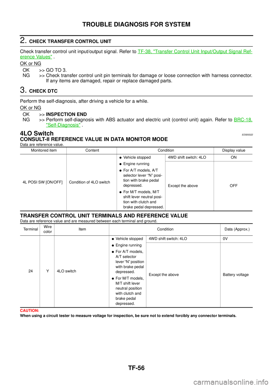
4LO SwitchEDS00322
CONSULT-II REFERENCE VALUE IN DATA MONITOR MODE
Data are reference value.
TRANSFER CONTROL UNIT TERMINALS AND REFERENCE VALUE
Data are reference value and are measured between each terminal and ground.
CAUTION:
When using a circuit tester to measure voltage for inspection, be sure not to extend forcibly any connector terminals.Monitored item Content Condition Display value
4L POSI SW [ON/OFF] Condition of 4LO switch
lVehicle stopped
lEngine running
lFor A/T models, A/T
selector lever “N” posi-
tion with brake pedal
depressed.
lFor M/T models, M/T
shift lever neutral posi-
tion with clutch and
brake pedal depressed.4WD shift switch: 4LO ON
Except the above OFF
Te r m i n a lWire
colorItem Condition Data (Approx.)
24 Y 4LO switch
lVehicle stopped
lEngine running
lFor A/T models,
A/T selector
lever “N” position
with brake pedal
depressed.
lFor M/T models,
M/T shift lever
neutral position
with clutch and
brake pedal
depressed.4WD shift switch: 4LO 0V
Except the above Battery voltage