Page 828 of 3171
BRC-6
[ABS]
SYSTEM DESCRIPTION
Hydraulic Circuit Diagram
EFS005TN
SFIA3205E
Page 835 of 3171
TROUBLE DIAGNOSIS
BRC-13
[ABS]
C
D
E
G
H
I
J
K
L
MA
B
BRC
Wiring Diagram — ABS —EFS005TS
MFWA0131E
Page 852 of 3171
BRC-30
[ABS]
TROUBLE DIAGNOSIS
Inspection 6 Brake Fluid Level Switch Circuit
EFS005U5
INSPECTION PROCEDURE
1.CHECK BRAKE FLUID LEVEL SWITCH
1. Turn ignition switch OFF and disconnect brake fluid level switch
connector E65. For brake fluid level switch connector, refer to
DI-10, "
Wiring Diagram—METER—".
2. Check continuity between brake fluid level switch connector
E65.
OK or NG
OK >> GO TO 2.
NG >> Replace reservoir tank. Refer toBR-17, "
BRAKE MASTER CYLINDER".
SFIA2940E
Brake fluid level switch Measurement condition Continuity
1, 2When fulling the brake fluid up No
When the brake fluid is insufficient Yes
Page 854 of 3171
![NISSAN NAVARA 2005 Repair Workshop Manual BRC-32
[ABS]
TROUBLE DIAGNOSIS
Inspection 7 Parking Brake Switch Circuit
EFS005U6
INSPECTION PROCEDURE
1.CHECK PARKING BRAKE SWITCH
1. Turn ignition switch OFF and disconnect parking brake switch
conn](/manual-img/5/57362/w960_57362-853.png "NISSAN NAVARA 2005 Repair Workshop Manual BRC-32
[ABS]
TROUBLE DIAGNOSIS
Inspection 7 Parking Brake Switch Circuit
EFS005U6
INSPECTION PROCEDURE
1.CHECK PARKING BRAKE SWITCH
1. Turn ignition switch OFF and disconnect parking brake switch
conn")
BRC-32
[ABS]
TROUBLE DIAGNOSIS
Inspection 7 Parking Brake Switch Circuit
EFS005U6
INSPECTION PROCEDURE
1.CHECK PARKING BRAKE SWITCH
1. Turn ignition switch OFF and disconnect parking brake switch
connector (LHD model: B12, RHD model: B109). For brake fluid
level switch, refer toDI-10, "
Wiring Diagram—METER—".
2. Check continuity between parking brake switch connector and
ground.
OK or NG
OK >> GO TO 2.
NG >> Replace parking brake switch.
2.CHECK HARNESS
1. Disconnect combination meter connector M23.
2. Check continuity between parking brake switch connector (LHD
model: B12, RHD model: B109), combination meter connector
M23 and ground.
OK or NG
OK >> INSPECTION END
NG >> If the open or short in harness, repair or replace harness.
SFIA2935E
Measurement condition Continuity
When the parking brake pedal is operated. Yes
When the parking brake pedal is not operated. No
SFIA3055E
Parking brake switch
(harness connector B12, B109)Combination meter
(harness connector M23)Continuity
131Yes
1 Ground No
Page 911 of 3171

DI-1
DRIVER INFORMATION SYSTEM
K ELECTRICAL
CONTENTS
C
D
E
F
G
H
I
J
L
M
SECTIONDI
A
B
DI
DRIVER INFORMATION SYSTEM
PRECAUTION ............................................................ 3
Precautions for Supplemental Restraint System
(SRS)“AIRBAG”and“SEATBELTPRE-TEN-
SIONER” .................................................................. 3
Wiring Diagrams and Trouble Diagnosis .................. 3
COMBINATION METERS ........................................... 4
System Description .................................................. 4
UNIFIED METER CONTROL UNIT ...................... 4
POWER SUPPLY AND GROUND CIRCUIT ........ 4
SPEEDOMETER ................................................... 4
TACHOMETER ..................................................... 4
WATER TEMPERATURE GAUGE ........................ 4
FUEL GAUGE ....................................................... 5
ODO/TRIP METER ............................................... 5
TRIP COMPUTER ................................................ 5
ENGINE OIL MAINTENANCE INFORMATION..... 6
METER ILLUMINATION CONTROL ..................... 6
CLOCK .................................................................. 6
AMBIENT AIR TEMPERATURE INDICATION ...... 6
Component Parts and Harness Connector Location..... 7
Arrangement of Combination Meter ......................... 8
Internal Circuit .......................................................... 9
Wiring Diagram — METER — ................................ 10
Terminals and Reference Value for Combination
Meter ...................................................................... 12
Self-Diagnosis Mode of Combination Meter ........... 13
FUNCTION .......................................................... 13
OPERATION PROCEDURE ............................... 13
TEST ITEM ......................................................... 13
CONSULT-II Function (METER) ............................. 15
CONSULT-II BASIC OPERATION ....................... 15
SELF-DIAG RESULTS ........................................ 16
DATA MONITOR ................................................. 17
Trouble Diagnosis .................................................. 18
HOW TO PERFORM TROUBLE DIAGNOSIS ... 18
PRELIMINARY CHECK ...................................... 19
Symptom Chart ...................................................... 19
Power Supply and Ground Circuit Inspection ........ 19
Vehicle Speed Signal Inspection ............................ 20
Engine Speed Signal Inspection ............................ 21Engine Coolant Temperature Signal Inspection ..... 21
Fuel Level Sensor Signal Inspection ...................... 22
Ambient Sensor Signal Inspection .......................... 24
Fuel Gauge Fluctuates, Indicates Wrong Value, or
Varies ...................................................................... 25
Fuel Gauge Does Not Move to Full position ........... 25
DTC [U1000] CAN Communication Circuit ............. 26
DTC [B2205] Vehicle Speed Circuit ........................ 26
Electrical Components Inspection .......................... 27
FUEL LEVEL SENSOR UNIT CHECK ................ 27
AMBIENT SENSOR CHECK ............................... 27
Removal and Installation of Combination Meter ..... 27
WARNING LAMPS .................................................... 28
System Description ................................................. 28
OIL PRESSURE WARNING LAMP ..................... 28
Component Parts and Harness Connector Location... 28
Schematic ............................................................... 29
Wiring Diagram — WARN — .................................. 30
A/T MODELS ....................................................... 30
M/T MODELS ...................................................... 37
Oil Pressure Warning Lamp Stays Off (Ignition
Switch ON) ............................................................. 44
Oil Pressure Warning Lamp Does Not Turn Off (Oil
Pressure Is Normal) ................................................ 45
Oil Pressure Warning Lamp Keeps Blinking (Oil
Level Is Normal) ..................................................... 46
Component Inspection ............................................ 47
OIL PRESSURE SWITCH ................................... 47
OIL LEVEL SENSOR .......................................... 47
A/T INDICATOR ........................................................ 48
System Description ................................................. 48
Wiring Diagram — AT/IND — ................................. 49
A/T Indicator Does Not Illuminate ........................... 50
WARNING CHIME ..................................................... 51
System Description ................................................. 51
POWER SUPPLY AND GROUND CIRCUIT ....... 51
LIGHT WARNING CHIME ................................... 51
KEY REMINDER WARNING CHIME .................. 51
LOW-FUEL WARNING CHIME ........................... 51
SEAT BELT WARNING CHIME ........................... 52
Page 912 of 3171

DI-2
Component Parts and Harness Connector Location... 52
Wiring Diagram — CHIME — ................................. 53
LHD MODELS ..................................................... 53
RHD MODELS ..................................................... 55
Terminals and Reference Value for BCM ................ 57
Terminals and Reference Value for Combination
Meter ...................................................................... 57
CONSULT-II Function (BCM) .................................. 58
DIAGNOSTIC ITEMS DESCRIPTION ................. 58
CONSULT-II BASIC OPERATION PROCEDURE
... 58
DATA MONITOR .................................................. 59
ACTIVE TEST ..................................................... 59
SELF-DIAG RESULTS ........................................ 60
Trouble Diagnosis ................................................... 60
HOW TO PERFORM TROUBLE DIAGNOSIS .... 60
PRELIMINARY INSPECTION ............................. 60
SYMPTOM CHART ............................................. 61
Meter Buzzer Circuit Inspection .............................. 61Lighting Switch Signal Inspection ........................... 62
Front Door Switch (Driver Side) Signal Inspection... 62
Seat Belt Buckle Switch Signal Inspection (Driver
Side) ........................................................................ 63
Electrical Component Inspection ............................ 64
FRONT DOOR SWITCH (DRIVER SIDE) ........... 64
SEAT BELT BUCKLE SWITCH (DRIVER SIDE)... 64
CAN COMMUNICATION ........................................... 65
System Description ................................................. 65
CAN Communication Unit ....................................... 65
COMPASS ................................................................. 66
System Description ................................................. 66
DIRECTION DISPLAY ......................................... 66
Zone Variation Change Procedure .......................... 66
Correction Functions of the Compass Display ........ 67
AUTOMATIC CORRECTION ............................... 67
MANUAL CORRECTION PROCEDURE ............. 67
Wiring Diagram — COMPAS — .............................. 68
Removal and Installation of Compass ..................... 69
Page 913 of 3171
PRECAUTION
DI-3
C
D
E
F
G
H
I
J
L
MA
B
DI
PRECAUTIONPFP:00011
Precautions for Supplemental Restraint System (SRS) “AIR BAG” and “SEAT
BELT PRE-TENSIONER”
EKS00N1V
The Supplemental Restraint System such as “AIR BAG” and “SEAT BELT PRE-TENSIONER”, used along
with a front seat belt, helps to reduce the risk or severity of injury to the driver and front passenger for certain
types of collision. Information necessary to service the system safely is included in the SRS and SB section of
this Service Manual.
WARNING:
lTo avoid rendering the SRS inoperative, which could increase the risk of personal injury or death
in the event of a collision which would result in air bag inflation, all maintenance must be per-
formed by an authorized NISSAN/INFINITI dealer.
lImproper maintenance, including incorrect removal and installation of the SRS, can lead to per-
sonal injury caused by unintentional activation of the system. For removal of Spiral Cable and Air
Bag Module, see the SRS section.
lDo not use electrical test equipment on any circuit related to the SRS unless instructed to in this
Service Manual. SRS wiring harnesses can be identified by yellow and/or orange harnesses or
harness connectors.
Wiring Diagrams and Trouble DiagnosisEKS00L8C
When reading wiring diagrams, refer to the following:
lGI-15, "How to Read Wiring Diagrams"
lPG-4, "POWER SUPPLY ROUTING CIRCUIT"for power distribution circuit
When performing trouble diagnosis, refer to the following:
lGI-11, "HOW TO FOLLOW TEST GROUPS IN TROUBLE DIAGNOSES"
lGI-24, "How to Perform Efficient Diagnosis for an Electrical Incident"
Page 920 of 3171
DI-10
COMBINATION METERS
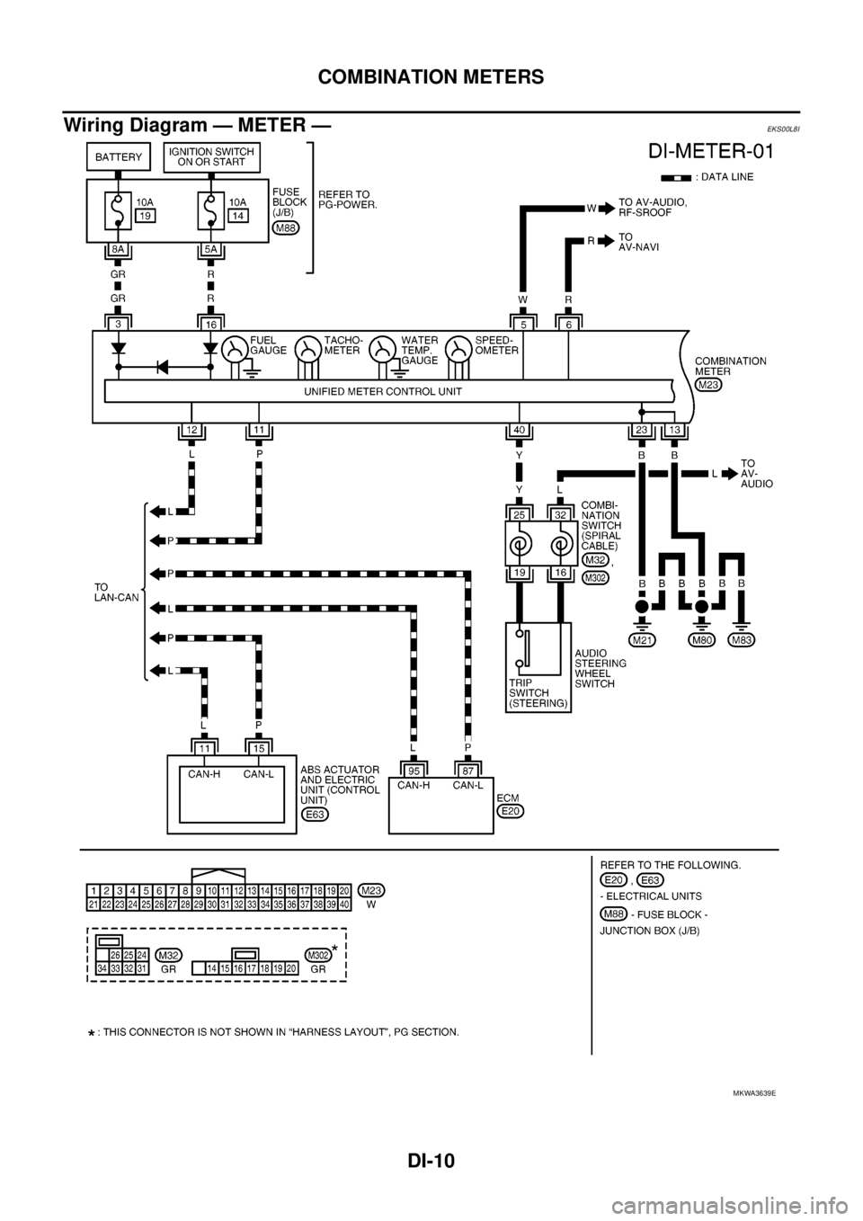
Wiring Diagram — METER —
EKS00L8I
MKWA3639E
![NISSAN NAVARA 2005 Repair Workshop Manual BRC-6
[ABS]
SYSTEM DESCRIPTION
Hydraulic Circuit Diagram
EFS005TN
SFIA3205E](/manual-img/5/57362/w960_57362-827.png "NISSAN NAVARA 2005 Repair Workshop Manual BRC-6
[ABS]
SYSTEM DESCRIPTION
Hydraulic Circuit Diagram
EFS005TN
SFIA3205E")
![NISSAN NAVARA 2005 Repair Workshop Manual TROUBLE DIAGNOSIS
BRC-13
[ABS]
C
D
E
G
H
I
J
K
L
MA
B
BRC
Wiring Diagram — ABS —EFS005TS
MFWA0131E](/manual-img/5/57362/w960_57362-834.png "NISSAN NAVARA 2005 Repair Workshop Manual TROUBLE DIAGNOSIS
BRC-13
[ABS]
C
D
E
G
H
I
J
K
L
MA
B
BRC
Wiring Diagram — ABS —EFS005TS
MFWA0131E")
![NISSAN NAVARA 2005 Repair Workshop Manual BRC-30
[ABS]
TROUBLE DIAGNOSIS
Inspection 6 Brake Fluid Level Switch Circuit
EFS005U5
INSPECTION PROCEDURE
1.CHECK BRAKE FLUID LEVEL SWITCH
1. Turn ignition switch OFF and disconnect brake fluid level](/manual-img/5/57362/w960_57362-851.png "NISSAN NAVARA 2005 Repair Workshop Manual BRC-30
[ABS]
TROUBLE DIAGNOSIS
Inspection 6 Brake Fluid Level Switch Circuit
EFS005U5
INSPECTION PROCEDURE
1.CHECK BRAKE FLUID LEVEL SWITCH
1. Turn ignition switch OFF and disconnect brake fluid level")