2005 NISSAN NAVARA diagram
[x] Cancel search: diagramPage 335 of 3171

ATC-1
AUTOMATIC AIR CONDITIONER
J AIR CONDITIONER
CONTENTS
C
D
E
F
G
H
I
K
L
M
SECTIONAT C
A
B
AT C
AUTOMATIC AIR CONDITIONER
PRECAUTIONS .......................................................... 4
Precautions for Supplemental Restraint System
(SRS)“AIRBAG”and“SEATBELTPRE-TEN-
SIONER” .................................................................. 4
Precautions for Working with HFC-134a (R-134a)..... 4
Contaminated Refrigerant ........................................ 4
General Refrigerant Precautions .............................. 5
Precautions for Refrigerant Connection ................... 5
ABOUT ONE-TOUCH JOINT ................................ 5
FEATURES OF NEW TYPE REFRIGERANT
CONNECTION ...................................................... 7
O-RING AND REFRIGERANT CONNECTION..... 9
Precautions for Servicing Compressor ................... 12
Precautions for Service Equipment ........................ 12
RECOVERY/RECYCLING EQUIPMENT ............ 12
ELECTRONIC LEAK DETECTOR ...................... 12
VACUUM PUMP ................................................. 13
MANIFOLD GAUGE SET .................................... 13
SERVICE HOSES ............................................... 13
SERVICE COUPLERS ........................................ 14
REFRIGERANT WEIGHT SCALE ...................... 14
CALIBRATING ACR4 WEIGHT SCALE .............. 14
CHARGING CYLINDER ...................................... 14
Precautions for Leak Detection Dye ....................... 14
IDENTIFICATION ................................................ 15
IDENTIFICATION LABEL FOR VEHICLE ........... 15
Wiring Diagrams and Trouble Diagnosis ................ 15
PREPARATION ......................................................... 16
Special Service Tools ............................................. 16
HFC-134a (R-134a) Service Tools and Equipment... 16
Commercial Service Tools ...................................... 19
REFRIGERATION SYSTEM ..................................... 20
Refrigerant Cycle ................................................... 20
REFRIGERANT FLOW ....................................... 20
FREEZE PROTECTION ..................................... 20
Refrigerant System Protection ............................... 20
REFRIGERANT PRESSURE SENSOR ............. 20
PRESSURE RELIEF VALVE ............................... 21
Components ........................................................... 22
REFRIGERATION SYSTEM ............................... 22LUBRICANT .............................................................. 24
Maintenance of Lubricant Quantity in Compressor... 24
LUBRICANT ........................................................ 24
CHECKING AND ADJUSTING ............................ 24
AIR CONDITIONER CONTROL ............................... 26
Description .............................................................. 26
Operation ................................................................ 26
AIR MIX DOORS CONTROL .............................. 26
BLOWER SPEED CONTROL ............................. 26
INTAKE DOOR CONTROL ................................. 26
MODE DOOR CONTROL ................................... 26
DEFROSTER DOOR CONTROL ........................ 26
MAGNET CLUTCH CONTROL ........................... 27
SELF-DIAGNOSTIC SYSTEM ............................ 27
Description of Control System ................................ 28
Control Operation ................................................... 28
DISPLAY SCREEN .............................................. 29
AUTO SWITCH ................................................... 29
TEMPERATURE CONTROL DIAL (TEMPERA-
TURE CONTROL) (DRIVER SIDE) ..................... 29
TEMPERATURE CONTROL DIAL (TEMPERA-
TURE CONTROL) (PASSENGER SIDE) ............ 29
TEMPERATURE CONTROL DIAL (TEMPERA-
TURE AND MODE CONTROL) (REAR) ............. 29
RECIRCULATION (REC) SWITCH ..................... 29
DEFROSTER (DEF) SWITCH ............................. 29
REAR WINDOW DEFOGGER SWITCH ............. 29
OFF SWITCH ...................................................... 29
A/C SWITCH ....................................................... 29
MODE SWITCH (FRONT) ................................... 29
FRONT BLOWER CONTROL DIAL .................... 29
MODE SWITCH (REAR) ..................................... 29
Discharge Air Flow ................................................. 30
FRONT ................................................................ 30
System Description ................................................. 31
SWITCHES AND THEIR CONTROL FUNCTION... 31
CAN Communication System Description .............. 32
TROUBLE DIAGNOSIS ............................................ 33
CONSULT-II Function (BCM) ................................. 33
CONSULT-II BASIC OPERATION ....................... 33
Page 336 of 3171

ATC-2
DATA MONITOR .................................................. 34
How to Perform Trouble Diagnosis for Quick and
Accurate Repair ...................................................... 35
WORK FLOW ...................................................... 35
SYMPTOM TABLE .............................................. 35
Component Parts and Harness Connector Location... 36
ENGINE COMPARTMENT .................................. 36
FRONT PASSENGER COMPARTMENT ............ 37
Schematic —LHD MODELS— ............................... 38
Wiring Diagram —A/C— —LHD MODELS— ......... 39
Schematic —RHD MODELS— ............................... 46
Wiring Diadram —A/C— —RHD MODELS— ......... 47
Front Air Control Terminals and Reference Value... 53
PIN CONNECTOR TERMINAL LAYOUT ............ 53
TERMINALS AND REFERENCE VALUE FOR
FRONT AIR CONTROL ....................................... 53
A/C System Self-diagnosis Function ...................... 55
DESCRIPTION .................................................... 55
Operational Check .................................................. 57
CHECKING MEMORY FUNCTION ..................... 57
CHECKING BLOWER ......................................... 57
CHECKING DISCHARGE AIR ............................ 58
CHECKING RECIRCULATION ............................ 58
CHECKING TEMPERATURE DECREASE ......... 58
CHECKING TEMPERATURE INCREASE .......... 59
CHECK A/C SWITCH .......................................... 59
CHECKING AUTO MODE ................................... 59
Power Supply and Ground Circuit for Front Air Con-
trol ........................................................................... 60
INSPECTION FLOW ........................................... 60
COMPONENT DESCRIPTION ............................ 61
DIAGNOSTIC PROCEDURE FOR A/C SYSTEM... 61
Mode Door Motor Circuit ........................................ 63
INSPECTION FLOW ........................................... 63
SYSTEM DESCRIPTION .................................... 64
COMPONENT DESCRIPTION ............................ 65
DIAGNOSTIC PROCEDURE FOR MODE
DOOR MOTOR ................................................... 65
Air Mix Door Motor Circuit ...................................... 68
INSPECTION FLOW ........................................... 68
SYSTEM DESCRIPTION .................................... 69
COMPONENT DESCRIPTION ............................ 70
DIAGNOSTIC PROCEDURE FOR AIR MIX
DOOR MOTOR (DRIVER) ................................... 71
DIAGNOSTIC PROCEDURE FOR AIR MIX
DOOR MOTOR (PASSENGER) .......................... 73
Intake Door Motor Circuit ........................................ 77
INSPECTION FLOW ........................................... 77
SYSTEM DESCRIPTION .................................... 78
COMPONENT DESCRIPTION ............................ 79
DIAGNOSTIC PROCEDURE FOR INTAKE
DOOR MOTOR ................................................... 79
Blower Motor Circuit ............................................... 80
INSPECTION FLOW ........................................... 80
SYSTEM DESCRIPTION .................................... 81
COMPONENT DESCRIPTION ............................ 82
DIAGNOSTIC PROCEDURE FOR BLOWER
MOTOR ............................................................... 82
COMPONENT INSPECTION .............................. 86Magnet Clutch Circuit .............................................. 87
INSPECTION FLOW ............................................ 87
SYSTEM DESCRIPTION ..................................... 88
DIAGNOSTIC PROCEDURE FOR MAGNET
CLUTCH .............................................................. 88
COMPONENT INSPECTION ............................... 92
Insufficient Cooling .................................................. 93
INSPECTION FLOW ............................................ 93
PERFORMANCE TEST DIAGNOSES ................ 94
PERFORMANCE CHART .................................... 96
TROUBLE DIAGNOSES FOR UNUSUAL PRES-
SURE ................................................................... 97
Insufficient Heating ...............................................100
INSPECTION FLOW ..........................................100
Noise .....................................................................101
INSPECTION FLOW ..........................................101
Self-diagnosis .......................................................103
INSPECTION FLOW ..........................................103
Memory Function ..................................................104
INSPECTION FLOW ..........................................104
Ambient Sensor Circuit .........................................105
COMPONENT DESCRIPTION ..........................105
AMBIENT TEMPERATURE INPUT PROCESS.105
DIAGNOSTIC PROCEDURE FOR AMBIENT
SENSOR ............................................................105
COMPONENT INSPECTION .............................107
In-vehicle Sensor Circuit .......................................108
COMPONENT DESCRIPTION ..........................108
DIAGNOSTIC PROCEDURE FOR IN-VEHICLE
SENSOR ............................................................109
COMPONENT INSPECTION ............................. 111
Optical Sensor Circuit ...........................................112
COMPONENT DESCRIPTION ..........................112
OPTICAL INPUT PROCESS .............................112
DIAGNOSTIC PROCEDURE FOR SUNLOAD
SENSOR ............................................................112
Intake Sensor Circuit .............................................114
COMPONENT DESCRIPTION ..........................114
DIAGNOSTIC PROCEDURE FOR INTAKE SEN-
SOR ...................................................................114
COMPONENT INSPECTION .............................115
CONTROL UNIT ......................................................116
Removal and Installation .......................................116
REMOVAL ..........................................................116
INSTALLATION ..................................................116
AMBIENT SENSOR ................................................117
Removal and Installation .......................................117
REMOVAL ..........................................................117
INSTALLATION ..................................................117
IN-VEHICLE SENSOR ............................................118
Removal and Installation .......................................118
REMOVAL ..........................................................118
INSTALLATION ..................................................118
OPTICAL SENSOR .................................................119
Removal and Installation .......................................119
INTAKE SENSOR ....................................................120
Removal and Installation .......................................120
REMOVAL ..........................................................120
INSTALLATION ..................................................120
Page 349 of 3171
PRECAUTIONS
ATC-15
C
D
E
F
G
H
I
K
L
MA
B
AT C
lA compressor shaft seal should not be repaired because of dye seepage. The compressor shaft seal
should only be repaired after confirming the leak with an electronic refrigerant leak detector (J-41995).
lAlways remove any remaining dye from the leak area after repairs are complete to avoid a misdiagnosis
during a future service.
lDo not allow dye to come into contact with painted body panels or interior components. If dye is spilled,
clean immediately with the approved dye cleaner. Fluorescent dye left on a surface for an extended period
of time cannot be removed.
lDo not spray the fluorescent dye cleaning agent on hot surfaces (engine exhaust manifold, etc.).
lDo not use more than one refrigerant dye bottle (1/4 ounce /7.4 cc) per A/C system.
lLeak detection dyes for HFC-134a (R-134a) and CFC-12 (R-12) A/C systems are different. Do not use
HFC-134a (R-134a) leak detection dye in CFC-12 (R-12) A/C system or CFC-12 (R-12) leak detector dye
in HFC-134a (R-134a) A/C systems or A/C system damage may result.
lThe fluorescent properties of the dye will remain for over three (3) years unless a compressor malfunction
occurs.
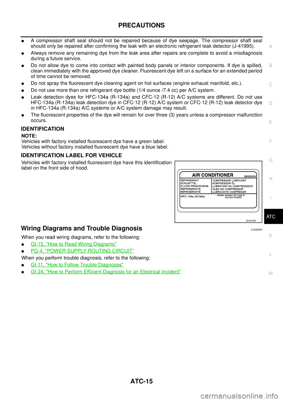
IDENTIFICATION
NOTE:
Vehicles with factory installed fluorescent dye have a green label.
Vehicles without factory installed fluorescent dye have a blue label.
IDENTIFICATION LABEL FOR VEHICLE
Vehicles with factory installed fluorescent dye have this identification
label on the front side of hood.
Wiring Diagrams and Trouble DiagnosisEJS006AS
When you read wiring diagrams, refer to the following:
lGI-15, "How to Read Wiring Diagrams"
lPG-4, "POWER SUPPLY ROUTING CIRCUIT"
When you perform trouble diagnosis, refer to the following:
lGI-11, "How to Follow Trouble Diagnoses"
lGI-24, "How to Perform Efficient Diagnosis for an Electrical Incident"
SHA749F
Page 373 of 3171
TROUBLE DIAGNOSIS
ATC-39
C
D
E
F
G
H
I
K
L
MA
B
AT C
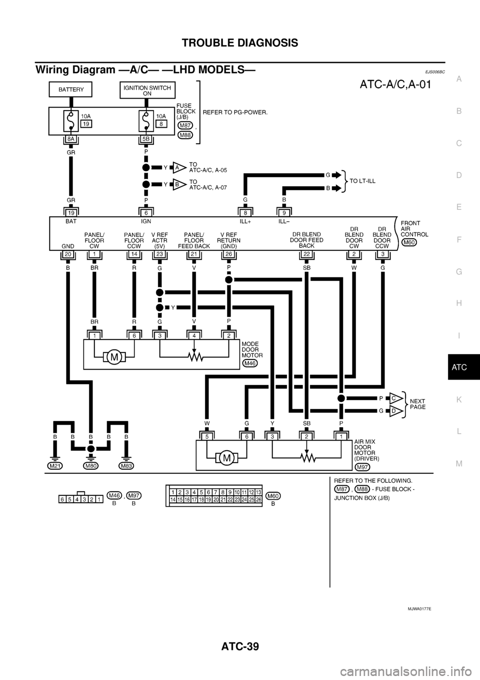
Wiring Diagram —A/C— —LHD MODELS—EJS006BC
MJWA0177E
Page 489 of 3171

AV-1
AUDIO-VISUAL SYSTEM
K ELECTRICAL
CONTENTS
C
D
E
F
G
H
I
J
L
M
SECTIONAV
A
B
AV
AUDIO-VISUAL SYSTEM
PRECAUTIONS .......................................................... 3
Precautions for Supplemental Restraint System
(SRS)“AIRBAG”and“SEATBELTPRE-TEN-
SIONER” .................................................................. 3
Wiring Diagrams and Trouble Diagnosis .................. 3
SYSTEM DESCRIPTION ............................................ 4
System Functions ..................................................... 4
AUDIO ................................................................... 4
NATS AUDIO LINK (WITHOUT NAVIGATION
SYSTEM) .............................................................. 4
VEHICLE INFORMATION SYSTEM ..................... 5
NAVIGATION SYSTEM ......................................... 5
HANDS-FREE PHONE ......................................... 7
Component Description ............................................ 8
AUDIO UNIT ......................................................... 8
NAVI CONTROL UNIT .......................................... 8
GPS ANTENNA .................................................... 9
DISPLAY UNIT ...................................................... 9
AV SWITCH .......................................................... 9
Component Parts Location ..................................... 10
Location Of Antenna .............................................. 10
Schematic — AUDIO — / With 1CD Player Type... 12
Wiring Diagram — AUDIO — / With 1CD Player Type
... 13
Schematic — AUDIO — / With 6CD Player Type... 16
Wiring Diagram — AUDIO — / With 6CD Player Type
... 17
Schematic — NAVI — ............................................ 20
Wiring Diagram — NAVI — .................................... 21
Schematic — NAVI — / COMM .............................. 28
Wiring Diagram — NAVI — / COMM ...................... 29
Wiring Diagram — TELEPHONE (PRE WIRE) —
/ Without NAVI ........................................................ 32
CAN Communication .............................................. 33
SYSTEM DESCRIPTION .................................... 33
TERMINALS AND REFERENCE VALUE FOR CON-
TROL UNIT ............................................................... 34
Audio Unit (1CD Player Type) ................................ 34
Audio Unit (6CD Player Type) Without NAVI .......... 35Audio Unit (With NAVI) ........................................... 37
NAVI Control Unit ................................................... 38
Display Unit ............................................................ 41
DIAGNOSIS SYSTEM ............................................... 44
Navigation System Diagnosis Function .................. 44
On Bord Self-Diagnosis Function ........................... 44
DESCRIPTION .................................................... 44
DIAGNOSIS ITEM ............................................... 44
OPERATION PROCEDURE ................................ 45
Self Diagnosis Mode ............................................... 46
ERROR DETECTION RANGE OF SELF-DIAG-
NOSIS MODE ..................................................... 47
DIAGNOSIS RESULTS ....................................... 47
Confirmation/Adjustment Mode .............................. 48
SCREEN TROUBLE DIAGNOSIS ...................... 49
VEHICLE SIGNALS ............................................ 49
SPEAKER TEST ................................................. 50
NAVIGATION ....................................................... 50
ERROR HISTORY ............................................... 51
VEHICLE CAN DIAGNOSIS ............................... 53
AV COMM DIAGNOSIS ....................................... 54
HANDSFREE PHONE ........................................ 54
BLUETOOTH ....................................................... 54
DELETE UNIT CONNECTION LOG ................... 55
CONSULT-II Functions ........................................... 56
CONSULT-II FUNCTIONS ................................... 56
CONSULT-II BASIC OPERATION PROCEDURE
... 56
SELF-DIAG RESULTS ........................................ 56
DATA MONITOR ................................................. 58
AV COMM MONITOR .......................................... 59
ECU PART NUMBER .......................................... 60
TROUBLE DIAGNOSIS ............................................ 61
Navigation System .................................................. 61
RGB Image ............................................................. 61
Voice Activated Control System ............................. 62
Steering Wheel Switch ............................................ 63
Component Parts Inspection .................................. 63
STEERING WHEEL SWITCH UNIT INSPEC-
Page 491 of 3171
PRECAUTIONS
AV-3
C
D
E
F
G
H
I
J
L
MA
B
AV
PRECAUTIONSPFP:00001
Precautions for Supplemental Restraint System (SRS) “AIR BAG” and “SEAT
BELT PRE-TENSIONER”
EKS00Q9X
The Supplemental Restraint System such as “AIR BAG” and “SEAT BELT PRE-TENSIONER”, used along
with a front seat belt, helps to reduce the risk or severity of injury to the driver and front passenger for certain
types of collision. Information necessary to service the system safely is included in the SRS and SB section of
this Service Manual.
WARNING:
lTo avoid rendering the SRS inoperative, which could increase the risk of personal injury or death
in the event of a collision which would result in air bag inflation, all maintenance must be per-
formed by an authorized NISSAN/INFINITI dealer.
lImproper maintenance, including incorrect removal and installation of the SRS, can lead to per-
sonal injury caused by unintentional activation of the system. For removal of Spiral Cable and Air
Bag Module, see the SRS section.
lDo not use electrical test equipment on any circuit related to the SRS unless instructed to in this
Service Manual. SRS wiring harnesses can be identified by yellow and/or orange harnesses or
harness connectors.
Wiring Diagrams and Trouble DiagnosisEKS00PE1
When reading wiring diagrams, refer to the following:
lRefer toGI-15, "HowtoReadWiringDiagrams".
lRefer toPG-4, "POWER SUPPLY ROUTING CIRCUIT".
When performing trouble diagnosis, refer to the following:
lRefer toGI-11, "HOW TO FOLLOW TEST GROUPS IN TROUBLE DIAGNOSES".
lRefer toGI-24, "How to Perform Efficient Diagnosis for an Electrical Incident".
Page 501 of 3171
SYSTEM DESCRIPTION
AV-13
C
D
E
F
G
H
I
J
L
MA
B
AV
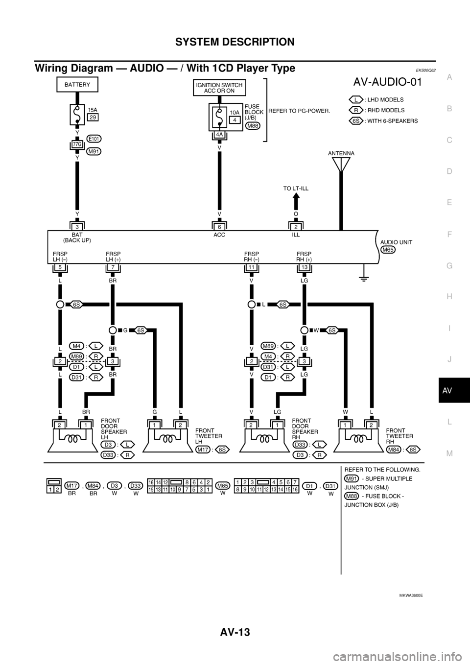
Wiring Diagram — AUDIO — / With 1CD Player TypeEKS00Q62
MKWA3600E
Page 505 of 3171
SYSTEM DESCRIPTION
AV-17
C
D
E
F
G
H
I
J
L
MA
B
AV
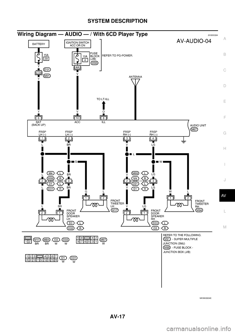
Wiring Diagram — AUDIO — / With 6CD Player TypeEKS00Q64
MKWA3604E