2005 NISSAN NAVARA engine
[x] Cancel search: enginePage 1337 of 3171
SERVICE DATA AND SPECIFICATIONS (SDS)
EC-357
C
D
E
F
G
H
I
J
K
L
MA
EC
SERVICE DATA AND SPECIFICATIONS (SDS)PFP:00100
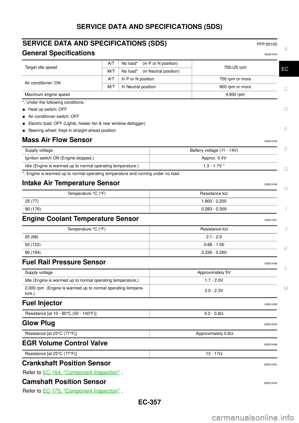
General SpecificationsEBS01KN4
*: Under the following conditions:
lHeat up switch: OFF
lAir conditioner switch: OFF
lElectric load: OFF (Lights, heater fan & rear window defogger)
lSteering wheel: Kept in straight-ahead position
Mass Air Flow SensorEBS01KN5
*: Engine is warmed up to normal operating temperature and running under no load.
Intake Air Temperature SensorEBS01KN6
Engine Coolant Temperature SensorEBS01KN7
Fuel Rail Pressure SensorEBS01KN8
Fuel InjectorEBS01KN9
Glow PlugEBS01KNA
EGR Volume Control ValveEBS01KNB
Crankshaft Position SensorEBS01KNC
Refer toEC-164, "Component Inspection".
Camshaft Position SensorEBS01KND
Refer toEC-175, "Component Inspection".
Target idle speedA/T No load* (in P or N position)
750±25 rpm
M/T No load* (in Neutral position)
Air conditioner: ONA/T In P or N position 750 rpm or more
M/T In Neutral position 800 rpm or more
Maximum engine speed4,900 rpm
Supply voltageBattery voltage (11 - 14V)
Ignition switch ON (Engine stopped.) Approx. 0.4V
Idle (Engine is warmed up to normal operating temperature.) 1.3 - 1.7V *
Temperature°C(°F) Resistance kW
25 (77)1.800 - 2.200
80 (176)0.283 - 0.359
Temperature°C(°F) Resistance kW
20 (68)2.1 - 2.9
50 (122)0.68 - 1.00
90 (194)0.236 - 0.260
Supply voltageApproximately 5V
Idle (Engine is warmed up to normal operating temperature.) 1.7 - 2.0V
2,000 rpm (Engine is warmed up to normal operating tempera-
ture.)2.0 - 2.3V
Resistance [at 10 - 60°C (50 - 140°F)] 0.2 - 0.8W
Resistance [at 25°C(77°F)] Approximately 0.8W
Resistance [at 25°C(77°F)] 13 - 17W
Page 1343 of 3171
PREPARATION
EI-5
C
D
E
F
G
H
J
K
L
MA
B
EI
PREPARATIONPFP:00002
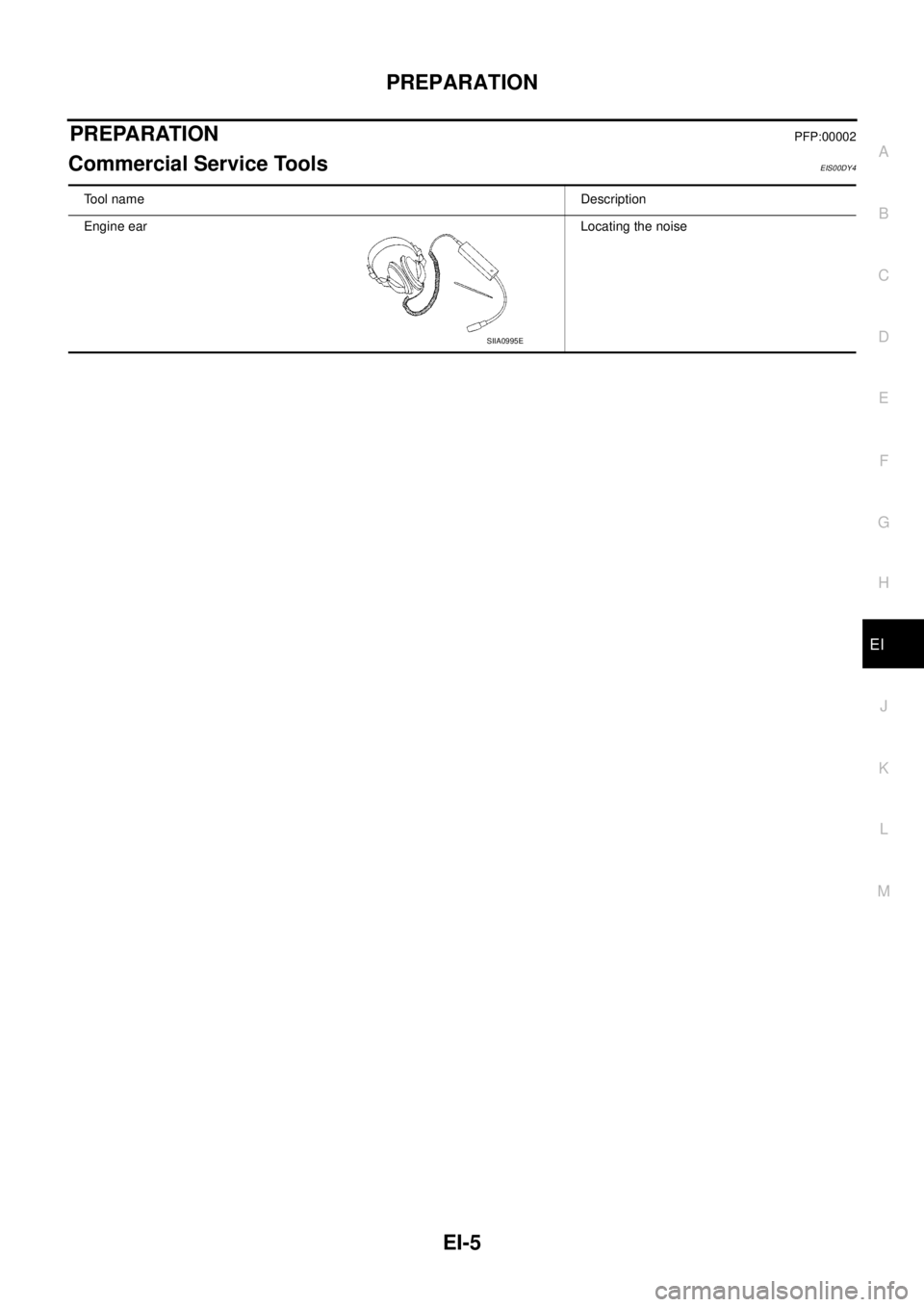
Commercial Service ToolsEIS00DY4
Tool nameDescription
Engine earLocating the noise
SIIA0995E
Page 1345 of 3171
SQUEAK AND RATTLE TROUBLE DIAGNOSES
EI-7
C
D
E
F
G
H
J
K
L
MA
B
EI
DUPLICATE THE NOISE AND TEST DRIVE
If possible, drive the vehicle with the customer until the noise is duplicated. Note any additional information on
the Diagnostic Worksheet regarding the conditions or location of the noise. This information can be used to
duplicate the same conditions when you confirm the repair.
If the noise can be duplicated easily during the test drive, to help identify the source of the noise, try to dupli-
cate the noise with the vehicle stopped by doing one or all of the following:
1) Close a door.
2) Tap or push/pull around the area where the noise appears to be coming from.
3) Rev the engine.
4) Use a floor jack to recreate vehicle “twist”.
5) At idle, apply engine load (electrical load, half-clutch on M/T model, drive position on A/T model).
6) Raisethevehicleonahoistandhitatirewitharubberhammer.
lDrive the vehicle and attempt to duplicate the conditions the customer states exist when the noise occurs.
lIf it is difficult to duplicate the noise, drive the vehicle slowly on an undulating or rough road to stress the
vehicle body.
CHECK RELATED SERVICE BULLETINS
After verifying the customer concern or symptom, check ASIST for Technical Service Bulletins (TSBs) related
to that concern or symptom.
If a TSB relates to the symptom, follow the procedure to repair the noise.
LOCATE THE NOISE AND IDENTIFY THE ROOT CAUSE
1. Narrow down the noise to a general area.To help pinpoint the source of the noise, use a listening tool
(Engine Ear and mechanic's stethoscope).
2. Narrow down the noise to a more specific area and identify the cause of the noise by:
lremoving the components in the area that you suspect the noise is coming from.
Do not use too much force when removing clips and fasteners, otherwise clips and fasteners can be bro-
ken or lost during the repair, resulting in the creation of new noise.
ltapping or pushing/pulling the component that you suspect is causing the noise.
Do not tap or push/pull the component with excessive force, otherwise the noise will be eliminated only
temporarily.
lfeeling for a vibration with your hand by touching the component(s) that you suspect is (are) causing the
noise.
lplacing a piece of paper between components that you suspect are causing the noise.
llooking for loose components and contact marks.
Refer toEI-7, "
Generic Squeak and Rattle Troubleshooting".
REPAIR THE CAUSE
lIf the cause is a loose component, tighten the component securely.
lIf the cause is insufficient clearance between components:
–separate components by repositioning or loosening and retightening the component, if possible.
–insulate components with a suitable insulator such as urethane pads, foam blocks, felt cloth tape or ure-
thane tape.
CAUTION:
Do not use excessive force as many components are constructed of plastic and may be damaged.
Always check with the Parts Department for the latest parts information.
CONFIRM THE REPAIR
Confirm that the cause of a noise is repaired by test driving the vehicle. Operate the vehicle under the same
conditions as when the noise originally occurred. Refer to the notes on the Diagnostic Worksheet.
Generic Squeak and Rattle TroubleshootingEIS00DY6
Refer to Table of Contents for specific component removal and installation information.
INSTRUMENT PANEL
Most incidents are caused by contact and movement between:
1. The cluster lid A and instrument panel
2. Acrylic lens and combination meter housing
Page 1347 of 3171
SQUEAK AND RATTLE TROUBLE DIAGNOSES
EI-9
C
D
E
F
G
H
J
K
L
MA
B
EI
SEATS
When isolating seat noise it's important to note the position the seat is in and the load placed on the seat when
the noise is present. These conditions should be duplicated when verifying and isolating the cause of the
noise.
Cause of seat noise include:
1. Headrest rods and holder
2. A squeak between the seat pad cushion and frame
3. The rear seatback lock and bracket
These noises can be isolated by moving or pressing on the suspected components while duplicating the con-
ditions under which the noise occurs. Most of these incidents can be repaired by repositioning the component
or applying urethane tape to the contact area.
UNDERHOOD
Some interior noise may be caused by components under the hood or on the engine wall. The noise is then
transmitted into the passenger compartment.
Causes of transmitted underhood noise include:
1. Any component mounted to the engine wall
2. Components that pass through the engine wall
3. Engine wall mounts and connectors
4. Loose radiator mounting pins
5. Hood bumpers out of adjustment
6. Hood striker out of adjustment
These noises can be difficult to isolate since they cannot be reached from the interior of the vehicle. The best
method is to secure, move or insulate one component at a time and test drive the vehicle. Also, engine RPM
or load can be changed to isolate the noise. Repairs can usually be made by moving, adjusting, securing, or
insulating the component causing the noise.
Page 1353 of 3171
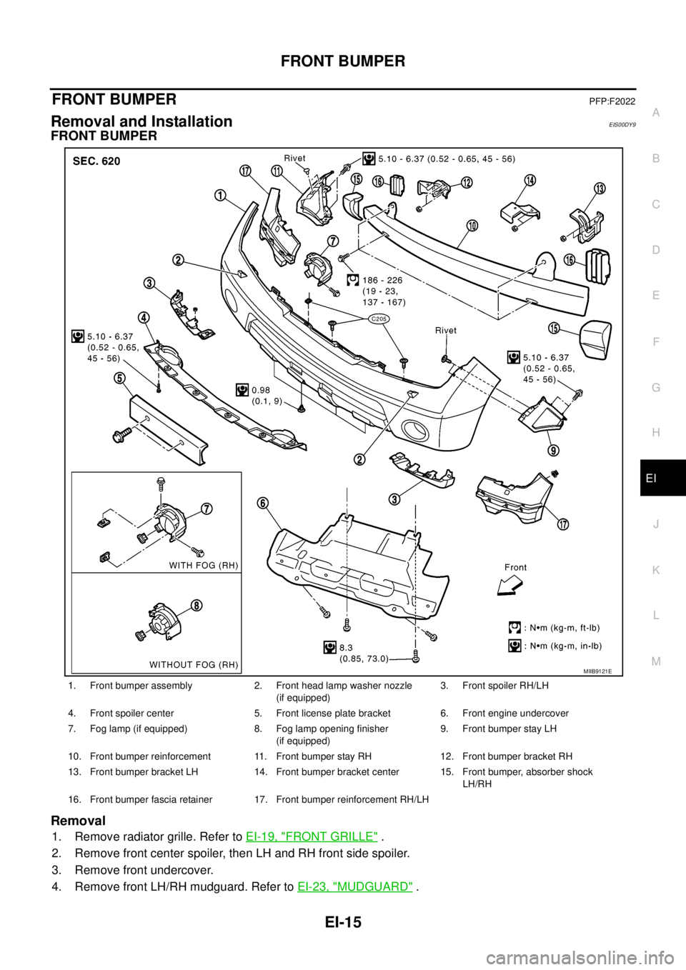
FRONT BUMPER
EI-15
C
D
E
F
G
H
J
K
L
MA
B
EI
FRONT BUMPERPFP:F2022
Removal and InstallationEIS00DY9
FRONT BUMPER
Removal
1. Remove radiator grille. Refer toEI-19, "FRONT GRILLE".
2. Remove front center spoiler, then LH and RH front side spoiler.
3. Remove front undercover.
4. Remove front LH/RH mudguard. Refer toEI-23, "
MUDGUARD".
1. Front bumper assembly 2. Front head lamp washer nozzle
(if equipped)3. Front spoiler RH/LH
4. Front spoiler center 5. Front license plate bracket 6. Front engine undercover
7. Fog lamp (if equipped) 8. Fog lamp opening finisher
(if equipped)9. Front bumper stay LH
10. Front bumper reinforcement 11. Front bumper stay RH 12. Front bumper bracket RH
13. Front bumper bracket LH 14. Front bumper bracket center 15. Front bumper, absorber shock
LH/RH
16. Front bumper fascia retainer 17. Front bumper reinforcement RH/LH
MIIB9121E
Page 1383 of 3171
EM-1
ENGINE MECHANICAL
B ENGINE
CONTENTS
C
D
E
F
G
H
I
J
K
L
M
SECTIONEM
A
EM
ENGINE MECHANICAL
PRECAUTIONS .......................................................... 4
Precautions for Draining Engine Coolant ................. 4
Precautions for Disconnecting Fuel Piping .............. 4
Precautions for Removal and Disassembly ............. 4
Precautions for Inspection, Repair and Replace-
ment ......................................................................... 4
Precautions for Assembly and Installation ............... 4
Parts Requiring Angle Tightening ............................. 4
Precautions For Liquid Gasket ................................. 5
REMOVAL OF LIQUID GASKET .......................... 5
LIQUID GASKET APPLICATION PROCEDURE..... 5
PREPARATION ........................................................... 6
Special Service Tools ............................................... 6
Commercial Service Tools ........................................ 8
NOISE, VIBRATION AND HARSHNESS (NVH)
TROUBLESHOOTING .............................................. 10
NVH Troubleshooting — Engine Noise .................. 10
Use the Chart Below to Help You Find the Cause
of the Symptom. ...................................................... 11
DRIVE BELTS ........................................................... 12
Checking Drive Belts .............................................. 12
Deflection Adjustment ............................................ 13
POWER STEERING OIL PUMP BELT ............... 13
A/C COMPRESSOR, ALTERNATOR AND
WATER PUMP BELT .......................................... 14
Removal and Installation ........................................ 14
REMOVAL ........................................................... 14
INSTALLATION ................................................... 14
AIR CLEANER AND AIR DUCT ............................... 15
Components ........................................................... 15
Removal and Installation ........................................ 15
REMOVAL ........................................................... 15
INSTALLATION ................................................... 16
CHANGING AIR CLEANER FILTER ................... 17
CHARGE AIR COOLER ........................................... 18
Components ........................................................... 18
Removal and Installation ........................................ 18
REMOVAL ........................................................... 18
INSPECTION AFTER REMOVAL ....................... 19
INSTALLATION ................................................... 19INTAKE MANIFOLD ................................................. 20
Components ........................................................... 20
Removal and Installation ........................................ 21
REMOVAL ........................................................... 21
INSPECTION AFTER REMOVAL ....................... 22
INSTALLATION ................................................... 22
INSPECTION AFTER INSTALLATION ................ 25
CATALYST ................................................................ 26
Components ........................................................... 26
Removal and Installation ........................................ 26
REMOVAL ........................................................... 26
INSTALLATION ................................................... 27
TURBO CHARGER ................................................... 28
Components ........................................................... 28
Removal and Installation ........................................ 29
REMOVAL ........................................................... 29
INSPECTION AFTER REMOVAL ....................... 30
TROUBLE DIAGNOSIS OF TURBOCHARGER... 32
INSTALLATION ................................................... 33
EXHAUST MANIFOLD ............................................. 34
Components ........................................................... 34
Removal and Installation ........................................ 34
REMOVAL ........................................................... 34
INSPECTION AFTER REMOVAL ....................... 35
INSTALLATION ................................................... 35
INSPECTION AFTER INSTALLATION ................ 35
OIL PAN AND OIL STRAINER ................................. 36
Components ........................................................... 36
Removal and Installation ........................................ 36
REMOVAL ........................................................... 36
INSPECTION AFTER REMOVAL ....................... 38
INSTALLATION ................................................... 38
INSPECTION AFTER INSTALLATION ................ 40
GLOW PLUG ............................................................ 41
Components ........................................................... 41
Removal and Installation ........................................ 41
REMOVAL ........................................................... 41
INSTALLATION ................................................... 41
VACUUM PUMP ........................................................ 42
Page 1384 of 3171
EM-2
Components ........................................................... 42
Removal and Installation ........................................ 42
INSPECTION BEFORE REMOVAL ..................... 42
REMOVAL ........................................................... 42
INSTALLATION .................................................... 43
INJECTION TUBE AND FUEL INJECTOR .............. 44
Components ........................................................... 44
Removal and Installation ........................................ 44
REMOVAL ........................................................... 44
INSTALLATION .................................................... 46
INSPECTION AFTER INSTALLATION ................ 48
FUEL PUMP .............................................................. 49
Components ........................................................... 49
Removal and Installation ........................................ 49
REMOVAL ........................................................... 49
INSPECTION AFTER REMOVAL ........................ 52
INSTALLATION .................................................... 52
ROCKER COVER ..................................................... 56
Components ........................................................... 56
Removal and Installation ........................................ 56
REMOVAL ........................................................... 56
INSTALLATION .................................................... 57
INSPECTION AFTER INSTALLATION ................ 58
CAMSHAFT ............................................................... 59
Components ........................................................... 59
Removal and Installation ........................................ 59
REMOVAL ........................................................... 59
INSPECTION AFTER REMOVAL ........................ 60
INSTALLATION .................................................... 63
INSPECTION AFTER INSTALLATION ................ 65
Valve Clearance ...................................................... 66
INSPECTION ....................................................... 66
ADJUSTMENTS .................................................. 67
OIL SEAL .................................................................. 70
Removal and Installation of Valve Oil Seal ............. 70
REMOVAL ........................................................... 70
INSTALLATION .................................................... 70
Removal and Installation of Front Oil Seal ............. 71
REMOVAL ........................................................... 71
INSTALLATION .................................................... 71
Removal and Installation of Rear Oil Seal .............. 72
REMOVAL ........................................................... 72
INSTALLATION .................................................... 72
SECONDARY TIMING CHAIN .................................. 73
Components ........................................................... 73
Removal and Installation ........................................ 73
REMOVAL ........................................................... 73
INSPECTION AFTER REMOVAL ........................ 75
INSTALLATION .................................................... 75
INSPECTION AFTER INSTALLATION ................ 77
PRIMARY TIMING CHAIN ........................................ 79
Components ........................................................... 79
Removal and Installation ........................................ 80
REMOVAL ........................................................... 80
INSPECTION AFTER REMOVAL ........................ 84
INSTALLATION .................................................... 85
INSPECTION AFTER INSTALLATION ................ 91CYLINDER HEAD ..................................................... 92
On-Vehicle Service ................................................. 92
CHECKING COMPRESSION PRESSURE ......... 92
Components ............................................................ 93
Removal and Installation ......................................... 94
REMOVAL ............................................................ 94
INSPECTION AFTER REMOVAL ........................ 94
INSTALLATION .................................................... 96
INSPECTION AFTER INSTALLATION ................ 98
Components ............................................................ 99
Disassembly and Assembly .................................... 99
DISASSEMBLY .................................................... 99
ASSEMBLY ........................................................100
INSPECTION AFTER DISASSEMBLY ..............101
ENGINE ASSEMBLY ...............................................106
Components ..........................................................106
Removal and Installation .......................................106
REMOVAL ..........................................................107
INSTALLATION ..................................................108
INSPECTION AFTER INSTALLATION ..............108
CYLINDER BLOCK .................................................110
Components ..........................................................110
Disassembly and Assembly .................................. 111
DISASSEMBLY .................................................. 111
ASSEMBLY ........................................................114
How to Select Piston and Bearing ........................121
DESCRIPTION ..................................................121
HOW TO SELECT PISTON ...............................121
HOW TO SELECT CONNECTING ROD BEAR-
ING .....................................................................122
HOW TO SELECT MAIN BEARING ..................123
Inspection After Disassembly ................................124
CRANKSHAFT END PLAY ................................124
CONNECTING ROD SIDE CLEARANCE .........125
PISTON TO PISTON PIN CLEARANCE ...........125
PISTON RING SIDE CLEARANCE ...................126
PISTON RING END GAP ..................................126
CONNECTING ROD BEND AND TORSION .....127
CONNECTING ROD BIG END INNER DIAME-
TER ....................................................................127
CONNECTING ROD BUSHING OIL CLEAR-
ANCE .................................................................127
CYLINDER BLOCK TOP SURFACE DISTOR-
TION ..................................................................128
MAIN BEARING HOUSING INNER DIAMETER.128
PISTON TO CYLINDER BORE CLEARANCE ..129
CRANKSHAFT MAIN JOURNAL DIAMETER ...130
CRANKSHAFT PIN JOURNAL DIAMETER ......130
CRANKSHAFT OUT-OF-ROUND AND TAPER.130
CRANKSHAFT RUNOUT ..................................131
CONNECTING ROD BEARING OIL CLEAR-
ANCE .................................................................131
MAIN BEARING OIL CLEARANCE ...................132
CRUSH HEIGHT OF MAIN BEARING ..............132
CRUSH HEIGHT OF CONNECTING ROD
Page 1386 of 3171
EM-4
PRECAUTIONS
PRECAUTIONS
PFP:00001
Precautions for Draining Engine CoolantEBS01E5H
Drain engine coolant when engine is cooled.
Precautions for Disconnecting Fuel PipingEBS01E5I
lBefore starting work, make sure no fire or spark producing items are in the work area.
lAfter disconnecting pipes, plug openings to stop fuel leakage.
Precautions for Removal and DisassemblyEBS01E5J
lWhen instructed to use SST, use the specified tools. Always be careful to work safely, avoid forceful or
uninstructed operations.
lExercise maximum care to avoid damage to mating or sliding surfaces.
lCover openings of engine system with tape or the equivalent, if necessary, to seal out foreign materials.
lMark and arrange disassembly parts in an organized way for easy troubleshooting and re-assembly.
lWhen loosening nuts and bolts, as a basic rule, start with the one furthest outside, then the one diagonally
opposite, and so on. If the order of loosening is specified, do exactly as specified.
Precautions for Inspection, Repair and ReplacementEBS01E5K
Before repairing or replacing, thoroughly inspect parts. Inspect new replacement parts in the same way, and
replace if necessary.
Precautions for Assembly and InstallationEBS01E5L
lUsetorquewrenchtotightenboltsornutstospecification.
lWhen tightening nuts and bolts, as a basic rule, equally tighten in several different steps starting with the
ones in center, then ones on inside and outside diagonally in this order. If the order of tightening is speci-
fied, do exactly as specified.
lReplace with new liquid gasket, packing, oil seal or O-ring.
lDowel pins are used for several parts alignment. When replacing and reassembling parts with dowel pins,
make sure that dowel pins are installed in the original position.
lThoroughly wash, clean, and air-blow each part. Carefully check engine oil or engine coolant passages for
any restriction and blockage.
lAvoid damaging sliding or mating surfaces. Completely remove foreign materials such as cloth lint or dust.
Before assembly, oil sliding surfaces well.
lRelease air within route when refilling after draining engine coolant.
lAfter repairing, start engine and increase engine speed to check engine coolant, fuel, engine oil, and
exhaust systems for leakage.
Parts Requiring Angle TighteningEBS01E5M
lUse an angle wrench [SST: KV10112100] for the final tightening of the following engine parts:
–Cylinder head bolts
–Main bearing cap bolts
–Connecting rod cap nuts
–Crankshaft pulley bolt (No angle wrench is required as the bolt flange is provided with notches for angle
tightening)
lDo not use a torque value for final tightening.
lThe torque value for these parts are for a preliminary step.
lEnsure thread and seat surfaces are clean and coated with engine oil.