2005 NISSAN NAVARA engine
[x] Cancel search: enginePage 1294 of 3171

EC-314
INTAKE AIR CONTROL VALVE CONTROL SOLENOID VALVE
INTAKE AIR CONTROL VALVE CONTROL SOLENOID VALVE
PFP:16188
DescriptionEBS01KM5
Vibration when stopping the engine can be controlled by cutting
intake air right before the fuel is cut. The intake air control valve con-
trol solenoid valve (1) controls the ON-OFF load of the intake air
control valve actuator. As a result, the intake air control valve control
solenoid valve will be turned ON when the ignition switch is turned
OFF with the engine running and when the engine stalls. After the
engine has stopped, the intake air control valve control solenoid
valve will return to fully open.
l: Vehicle front
lElectronic controlled engine mount control solenoid valve (2)
lOil filter (3)
ECM Terminals and Reference ValueEBS01KM6
Specification data are reference valves, and are measured between each terminal and ground.
CAUTION:
Do not use ECM ground terminals when measuring input/output voltage. Doing so may damage the
ECM's transistor. Use a ground other than ECM terminals, such as the ground.
MBIB1226E
TERMI-
NAL
NO.WIRE
COLORITEM CONDITIONDATA
(DC Voltage and Pulse Signal)
15 GRIntake air control valve
control solenoid valve[Engine is running]BATTERY VOLTAGE
(11 - 14V)
[Engine is running]
[Ignition switch OFF]
lFor a few seconds after turning ignition
switch OFFApproximately 0.3V
105
11 3BR
BRECM relay (self shut-off)[Ignition switch OFF]
lFor a few seconds after turning ignition
switch OFFApproximately 1.0V
[Ignition switch OFF]
lMore than a few seconds after turning igni-
tion switch OFFBATTERY VOLTAGE
(11 - 14V)
11 9
120R
GPower supply for ECM[Ignition switch ON]BATTERY VOLTAGE
(11 - 14V)
Page 1296 of 3171
EC-316
INTAKE AIR CONTROL VALVE CONTROL SOLENOID VALVE
Diagnostic Procedure
EBS01KM8
1.CHECK OVERALL FUNCTION
1. Start engine and let it idle.
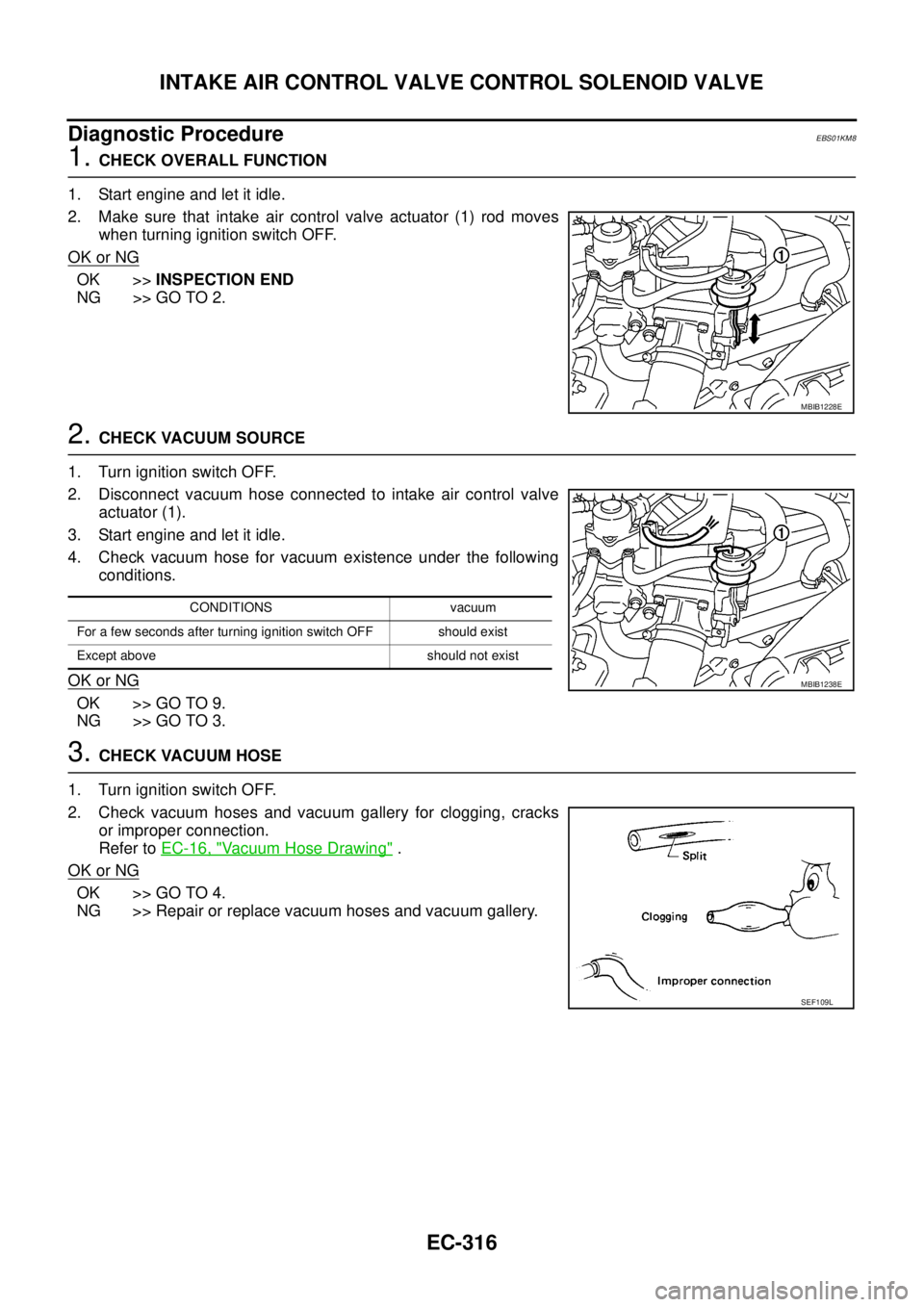
2. Make sure that intake air control valve actuator (1) rod moves
when turning ignition switch OFF.
OK or NG
OK >>INSPECTION END
NG >> GO TO 2.
2.CHECK VACUUM SOURCE
1. Turn ignition switch OFF.
2. Disconnect vacuum hose connected to intake air control valve
actuator (1).
3. Start engine and let it idle.
4. Check vacuum hose for vacuum existence under the following
conditions.
OK or NG
OK >> GO TO 9.
NG >> GO TO 3.
3.CHECK VACUUM HOSE
1. Turn ignition switch OFF.
2. Check vacuum hoses and vacuum gallery for clogging, cracks
or improper connection.
Refer toEC-16, "
Vacuum Hose Drawing".
OK or NG
OK >> GO TO 4.
NG >> Repair or replace vacuum hoses and vacuum gallery.
MBIB1228E
CONDITIONS vacuum
For a few seconds after turning ignition switch OFF should exist
Except above should not exist
MBIB1238E
SEF109L
Page 1297 of 3171
INTAKE AIR CONTROL VALVE CONTROL SOLENOID VALVE
EC-317
C
D
E
F
G
H
I
J
K
L
MA
EC
4.CHECK INTAKE AIR CONTROL VALVE CONTROL SOLENOID VALVE POWER SUPPLY CIRCUIT
1. Turn ignition switch OFF.
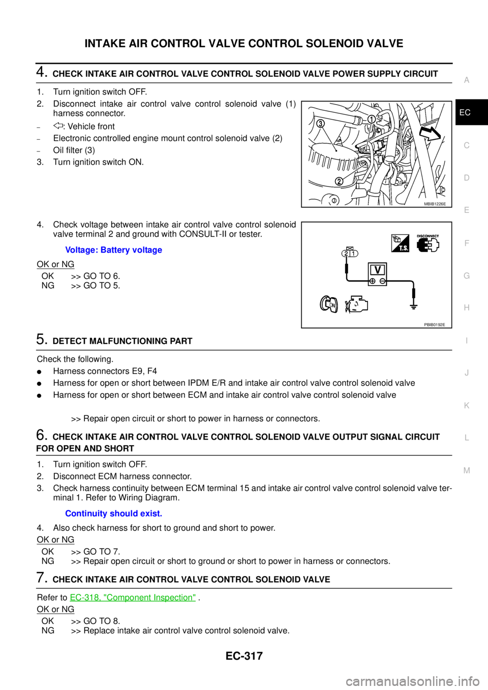
2. Disconnect intake air control valve control solenoid valve (1)
harness connector.
–: Vehicle front
–Electronic controlled engine mount control solenoid valve (2)
–Oil filter (3)
3. Turn ignition switch ON.
4. Check voltage between intake air control valve control solenoid
valve terminal 2 and ground with CONSULT-II or tester.
OK or NG
OK >> GO TO 6.
NG >> GO TO 5.
5.DETECT MALFUNCTIONING PART
Check the following.
lHarness connectors E9, F4
lHarness for open or short between IPDM E/R and intake air control valve control solenoid valve
lHarness for open or short between ECM and intake air control valve control solenoid valve
>> Repair open circuit or short to power in harness or connectors.
6.CHECK INTAKE AIR CONTROL VALVE CONTROL SOLENOID VALVE OUTPUT SIGNAL CIRCUIT
FOR OPEN AND SHORT
1. Turn ignition switch OFF.
2. Disconnect ECM harness connector.
3. Check harness continuity between ECM terminal 15 and intake air control valve control solenoid valve ter-
minal 1. Refer to Wiring Diagram.
4. Also check harness for short to ground and short to power.
OK or NG
OK >> GO TO 7.
NG >> Repair open circuit or short to ground or short to power in harness or connectors.
7.CHECK INTAKE AIR CONTROL VALVE CONTROL SOLENOID VALVE
Refer toEC-318, "
Component Inspection".
OK or NG
OK >> GO TO 8.
NG >> Replace intake air control valve control solenoid valve.
MBIB1226E
Voltage: Battery voltage
PBIB0192E
Continuity should exist.
Page 1298 of 3171
EC-318
INTAKE AIR CONTROL VALVE CONTROL SOLENOID VALVE
8.CHECK VACUUM PUMP
Refer toEM-42, "
VACUUM PUMP".
OK or NG
OK >> GO TO 9.
NG >> Replace vacuum pump assembly.
9.CHECK INTAKE AIR CONTROL VALVE ACTUATOR
1. Turn ignition switch OFF.
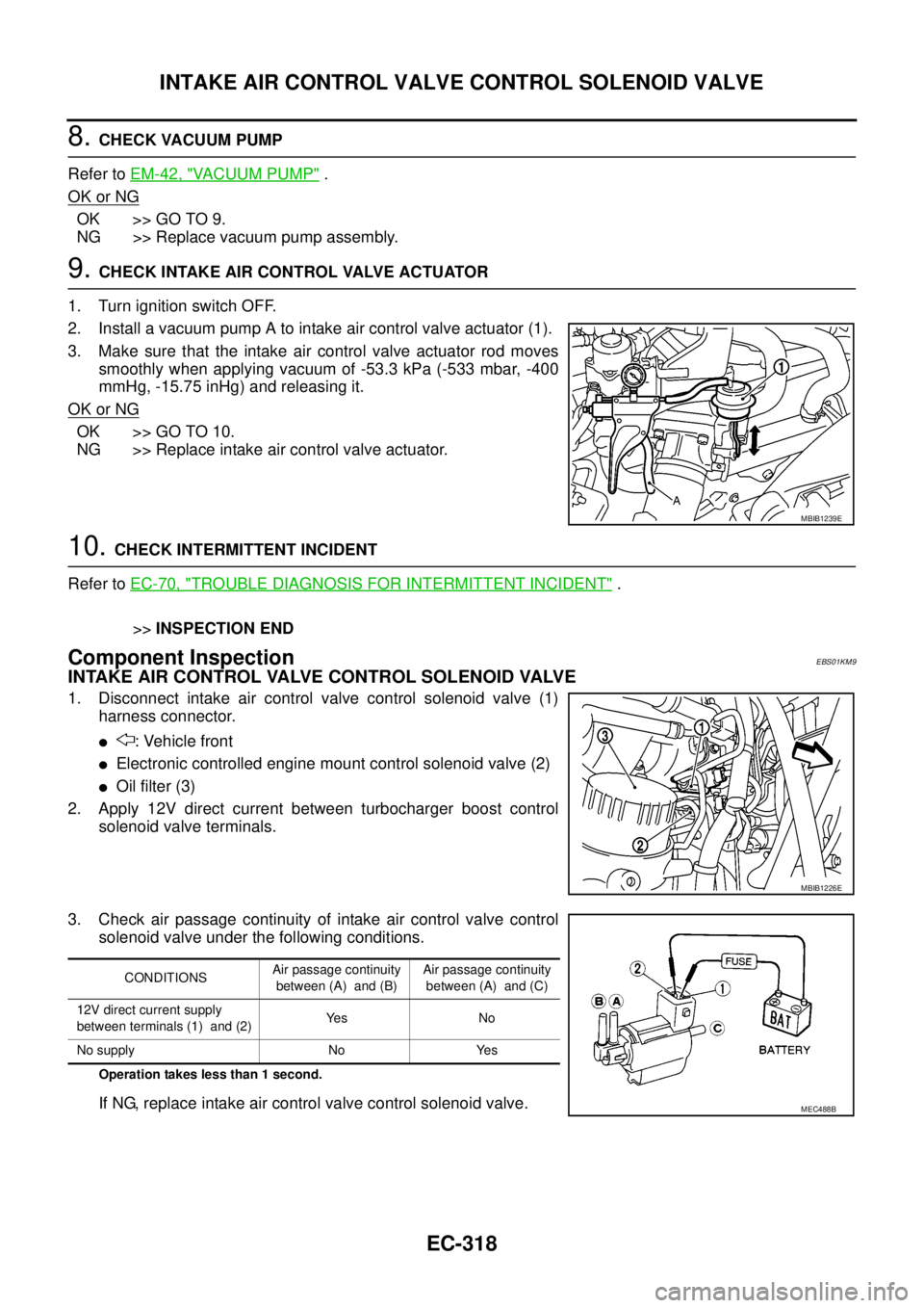
2. Install a vacuum pump A to intake air control valve actuator (1).
3. Make sure that the intake air control valve actuator rod moves
smoothly when applying vacuum of -53.3 kPa (-533 mbar, -400
mmHg, -15.75 inHg) and releasing it.
OK or NG
OK >> GO TO 10.
NG >> Replace intake air control valve actuator.
10.CHECK INTERMITTENT INCIDENT
Refer toEC-70, "
TROUBLE DIAGNOSIS FOR INTERMITTENT INCIDENT".
>>INSPECTION END
Component InspectionEBS01KM9
INTAKE AIR CONTROL VALVE CONTROL SOLENOID VALVE
1. Disconnect intake air control valve control solenoid valve (1)
harness connector.
l: Vehicle front
lElectronic controlled engine mount control solenoid valve (2)
lOil filter (3)
2. Apply 12V direct current between turbocharger boost control
solenoid valve terminals.
3. Check air passage continuity of intake air control valve control
solenoid valve under the following conditions.
Operation takes less than 1 second.
If NG, replace intake air control valve control solenoid valve.
MBIB1239E
MBIB1226E
CONDITIONSAir passage continuity
between (A) and (B)Air passage continuity
between (A) and (C)
12V direct current supply
between terminals (1) and (2)Ye s N o
No supply No Yes
MEC488B
Page 1299 of 3171

HEAT UP SWITCH
EC-319
C
D
E
F
G
H
I
J
K
L
MA
EC
HEAT UP SWITCHPFP:27666
DescriptionEBS01KMA
The heat up switch (1) is located on the lower side of the instrument
panel. This switch is used to speed up the heater's operation when
the engine is cold. When the ECM received the heat up switch ON
signal, the ECM increases the engine idle speed to 1,400 rpm to
warm up engine quickly.
This system works when all conditions listed below are met.
CONSULT-II Reference Value in Data Monitor ModeEBS01KMB
Specification data are reference values.
ECM Terminals and Reference ValueEBS01KMC
Specification data are reference values and are measured between each terminal and ground.
CAUTION:
Do not use ECM ground terminals when measuring input/output voltage. Doing so may result in dam-
age to the ECM's transistor. Use a ground other than ECM terminals, such as the ground.
Heat up switch ON
Shift lever P or N (A/T), Neutral (M/T)
Accelerator pedal Fully released
MBIB1221E
MONITOR ITEM CONDITION SPECIFICATION
WARM UP SW
lIgnition switch: ONHeat up switch: OFF OFF
Heat up switch: ON ON
TER-
MINAL
NO.WIRE
COLORITEM CONDITIONDATA
(DC Voltage)
13 Y Heat up switch[Ignition switch ON]
lHeat up switch: OFFApproximately 0.3V
[Ignition switch ON]
lHeat up switch: ONBATTERY VOLTAGE
(11 - 14V)
Page 1305 of 3171
REFRIGERANT PRESSURE SENSOR
EC-325
C
D
E
F
G
H
I
J
K
L
MA
EC
REFRIGERANT PRESSURE SENSORPFP:92136
Component DescriptionEBS01KMG
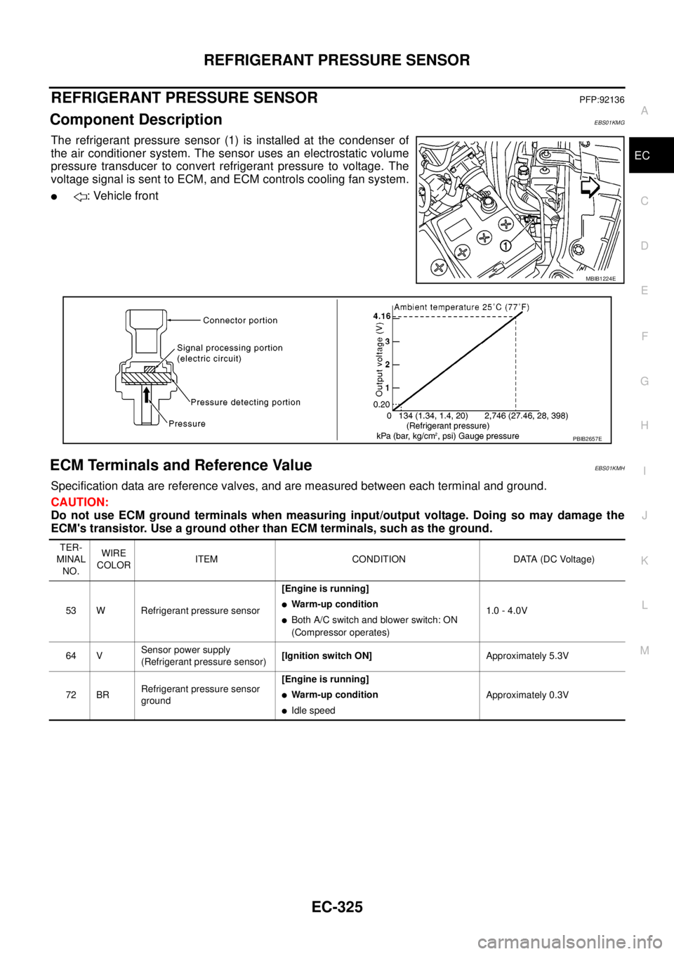
The refrigerant pressure sensor (1) is installed at the condenser of
the air conditioner system. The sensor uses an electrostatic volume
pressure transducer to convert refrigerant pressure to voltage. The
voltage signal is sent to ECM, and ECM controls cooling fan system.
l: Vehicle front
ECM Terminals and Reference ValueEBS01KMH
Specification data are reference valves, and are measured between each terminal and ground.
CAUTION:
Do not use ECM ground terminals when measuring input/output voltage. Doing so may damage the
ECM's transistor. Use a ground other than ECM terminals, such as the ground.
MBIB1224E
PBIB2657E
TER-
MINAL
NO.WIRE
COLORITEM CONDITION DATA (DC Voltage)
53 W Refrigerant pressure sensor[Engine is running]
lWarm-up condition
lBoth A/C switch and blower switch: ON
(Compressor operates)1.0 - 4.0V
64 VSensor power supply
(Refrigerant pressure sensor)[Ignition switch ON]Approximately 5.3V
72 BRRefrigerant pressure sensor
ground[Engine is running]
lWarm-up condition
lIdle speedApproximately 0.3V
Page 1307 of 3171
REFRIGERANT PRESSURE SENSOR
EC-327
C
D
E
F
G
H
I
J
K
L
MA
EC
Diagnostic ProcedureEBS01KMJ
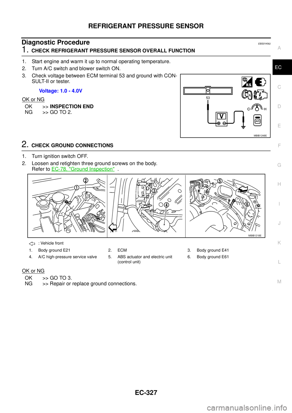
1.CHECK REFRIGERANT PRESSURE SENSOR OVERALL FUNCTION
1. Start engine and warm it up to normal operating temperature.
2. Turn A/C switch and blower switch ON.
3. Check voltage between ECM terminal 53 and ground with CON-
SULT-II or tester.
OK or NG
OK >>INSPECTION END
NG >> GO TO 2.
2.CHECK GROUND CONNECTIONS
1. Turn ignition switch OFF.
2. Loosen and retighten three ground screws on the body.
Refer toEC-78, "
Ground Inspection".
OK or NG
OK >> GO TO 3.
NG >> Repair or replace ground connections.Voltage: 1.0 - 4.0V
MBIB1248E
: Vehicle front
1. Body ground E21 2. ECM 3. Body ground E41
4. A/C high-pressure service valve 5. ABS actuator and electric unit
(control unit)6. Body ground E61
MBIB1218E
Page 1335 of 3171

AUTOMATIC SPEED CONTROL DEVICE (ASCD)
EC-355
C
D
E
F
G
H
I
J
K
L
MA
EC
AUTOMATIC SPEED CONTROL DEVICE (ASCD)PFP:18930
System DescriptionEBS01KN2
INPUT/OUTPUT SIGNAL CHART
*: This signal is sent to the ECM through CAN communication line.
BASIC ASCD SYSTEM
Refer to Owner's Manual for ASCD operating instructions.
Automatic Speed Control Device (ASCD) allows a driver to keep vehicle at predetermined constant speed
without depressing accelerator pedal. Driver can set vehicle speed in advance between approximately 40 km/
h(25MPH)and185km/h(115MPH).
ECM controls fuel injection value to regulate engine speed.
Operation status of ASCD is indicated by CRUISE indicator and SET indicator in combination meter. If any
malfunction occurs in ASCD system, it automatically deactivates control.
SET OPERATION
Press ASCD MAIN switch. (The CRUISE indicator in combination meter illuminates.)
When vehicle speed reaches a desired speed between approximately 40 km/h (25 MPH) and 185 km/h (115
MPH), press SET/COST switch. (Then SET indicator in combination meter illuminates.)
ACCEL OPERATION
If the RESUME/ACCELERATE switch is depressed during cruise control driving, increase the vehicle speed
until the switch is released or vehicle speed reaches maximum speed controlled by the system.
And then ASCD will keep the new set speed.
CANCEL OPERATION
When any of following conditions exist, cruise operation will be canceled.
lCANCEL switch is depressed
lMore than 2 switches at ASCD steering switch are depressed at the same time (Set speed will be cleared)
lBrake pedal is depressed
lClutch pedal is depressed or gear position is changed to the neutral position (M/T models)
lSelector lever is changed to N, P, R position (A/T models)
lVehicle speed decreased to 13 km/h (8 MPH) lower than the set speed
When the ECM detects any of the following conditions, the ECM will cancel the cruise operation and inform
the driver by blinking indicator lamp.
lMalfunction for some self-diagnoses regarding ASCD control: SET lamp will blink quickly.
If MAIN switch is turned to OFF during ASCD is activated, all of ASCD operations will be canceled and vehicle
speed memory will be erased.
COAST OPERATION
When the SET/COAST switch is depressed during cruise control driving, decrease vehicle set speed until the
switch is released. And then ASCD will keep the new set speed.
RESUME OPERATION
When the RESUME/ACCELERATE switch is depressed after cancel operation other than depressing MAIN
switch is performed, vehicle speed will return to last set speed. To resume vehicle set speed, vehicle condition
must meet following conditions.
Sensor Input signal to ECM ECM function Actuator
ASCD brake switch Brake pedal operation
ASCD vehicle speed control Fuel injector and Fuel pump Stop lamp switch Brake pedal operation
ASCD clutch switch (M/T) Clutch pedal operation
ASCD steering switch ASCD steering switch operation
Park/Neutral position (PNP)
switchGear position
Combination meter* Vehicle speed
TCM* Powertrain revolution