Page 2687 of 3171
RF-10
SUNROOF
SUNROOF
PFP:91210
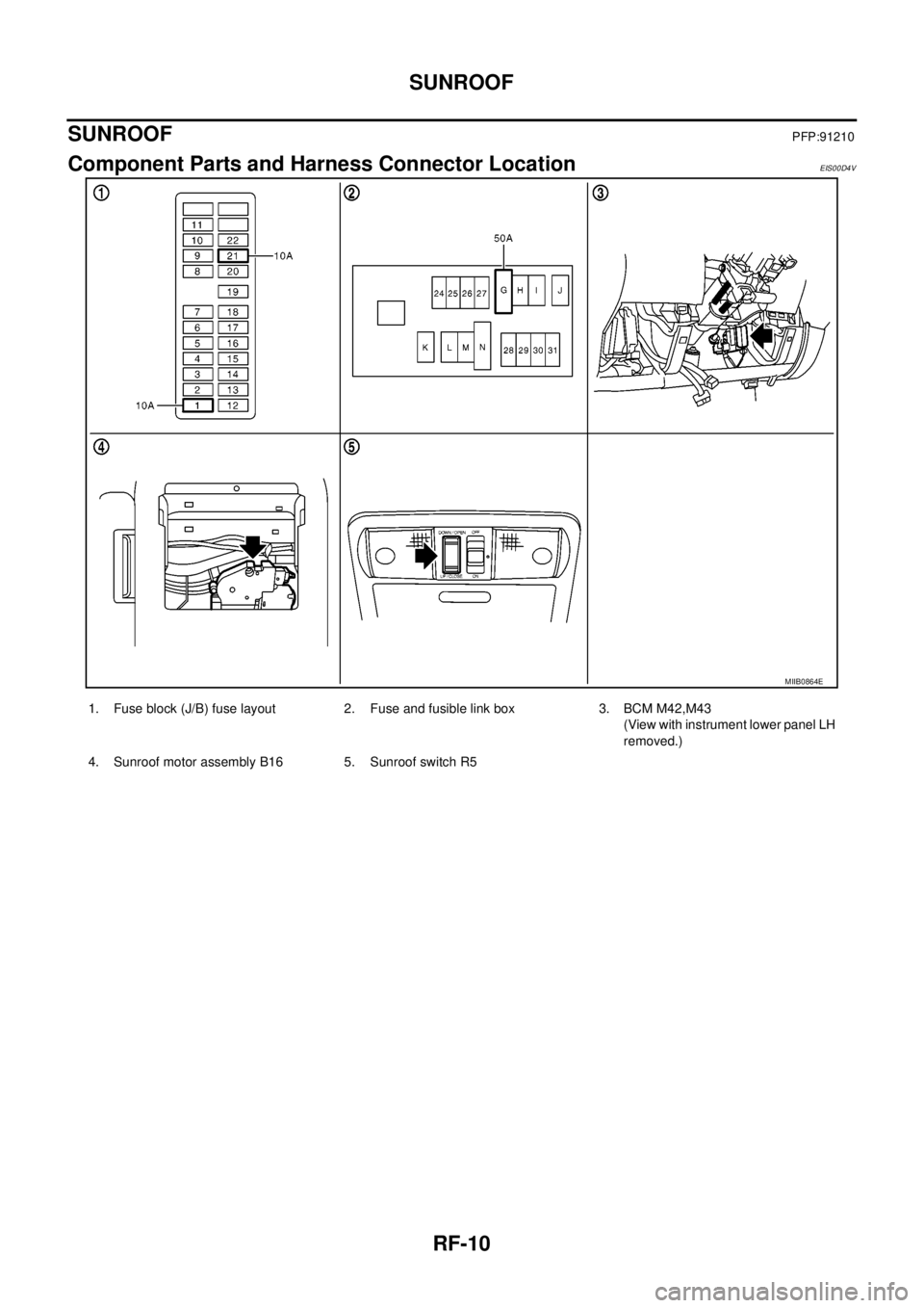
Component Parts and Harness Connector LocationEIS00D4V
MIIB0864E
1. Fuse block (J/B) fuse layout 2. Fuse and fusible link box 3. BCM M42,M43
(View with instrument lower panel LH
removed.)
4. Sunroof motor assembly B16 5. Sunroof switch R5
Page 2688 of 3171
SUNROOF
RF-11
C
D
E
F
G
H
J
K
L
MA
B
RF
System DescriptionEIS00D4W
Power supplied at all time
lthrough 50A fusible link (letterG, located in the fuse and fusible link box)
lto BCM terminal 57.
lthrough 10A fuse [No.21, located in the fuse block (J/B)]
lto BCM terminal 41.
lthrough BCM terminal 58
lto sunroof motor assembly terminal 7.
Ground is supplied
lto BCM terminal 55
lthrough body grounds M21, M80 and M83.
lto sunroof motor assembly terminal 10
lthrough body grounds B9 and B25.
When ignition switch ON or START position,
Power is supplied
lthrough 10A fuse [No.1, located in the fuse block (J/B)]
lto BCM terminal 3.
lthrough BCM terminal 53
lto sunroof motor assembly terminal 9.
TILT UP / SLIDE CLOSE OPERATION
When tilt up / slide close switch is pressed,
Ground is supplied
lto sunroof motor assembly terminal 1
lthrough sunroof switch terminal 3
lthrough sunroof switch terminal 2
lthrough body grounds M21, M80 and M83.
Then, the sunroof tilt up / slide close.
TILT DOWN / SLIDE OPEN OPERATION
When tilt down / slide open switch is pressed,
Ground is supplied
lto sunroof motor assembly terminal 5
lthrough sunroof switch terminal 1
lthrough sunroof switch terminal 2
lthrough body grounds M21, M80 and M83.
Then, the sunroof tilt down / slide open.
AUTO OPERATION
The power sunroof AUTO feature makes it possible to slide open and slide close or tilt up and tilt down the
sunroof without holding the sunroof switch in the TILT UP/SLIDE CLOSE, TILT DOWN/SLIDE OPEN position.
ANTI-PINCH FUNCTION
The CPU of sunroof motor assembly monitors the sunroof motor operation and the sunroof position (fully-
closed or other) by the signals from sunroof motor.
When sunroof motor detects an interruption during the following slide close and tilt down operation, sunroof
switch controls the motor for open and the sunroof will operate until it reaches full up position (when tilt down
operate) or 125 mm (4.92 in) or more in an open direction (during slide close operate).
lclose operation and tilt down when ignition switch is in the ON position.
Page 2689 of 3171
RF-12
SUNROOF
MEMORY RESET PROCEDURE
1. Please observe the following instructions while confirming the sunroof operation.
NOTE:
Do not disconnect the electronic power while the sunroof is operating or within 5 seconds after the sunroof
stops. (to wipe-out the memory of lid position and operating friction.)
2. Initialization of system should be conducted after the following conditions.
lWhen the battery is out or connector is disconnected while sunroof is operating or within 5 seconds
after sunroof stops.
lWhen the sunroof motor is changed.
lWhen an emergency handle is used.
lWhen the sunroof does not operate normally. (Incomplete initialization conditions)
INITIALIZATION PROCEDURE
If sunroof does not close or open normally, use following procedure to return sunroof operation to normal.
1. Close sunroof if it is not in close position. It may be necessary to repeatedly push TILT UP/SLIDE CLOSE
switch to close sunroof.
2. Tilt up sunroof, and release TILT UP/SLIDE CLOSE switch once.
3. Keep pushing TILT UP/SLIDE CLOSE switch. After 10seconds, glass lid will back up a few millimeters.
then will be stopped at normal tilt up position.
(Keep pushing TILT UP/SLIDE CLOSE switch during this operation.)
4. Within first 10 seconds of releasing TILT UP/SLIDE CLOSE switch, keep pushing TILT UP/SLIDE CLOSE
switch again. After 4 seconds, glass lid will be automatically TILT DOWN®SLIDE OPEN®SLIDE
CLOSE.
(Keep pushing TILT UP/SLIDE CLOSE switch during this operation.)
5. After glass lid stops, release TILT UP/SLIDE CLOSE switch later 0.5 seconds.
6. Initializing procedure is completed. Confirm proper operation of sunroof (slide open, slide close, tilt up, tilt
down).
Page 2690 of 3171
SUNROOF
RF-13
C
D
E
F
G
H
J
K
L
MA
B
RF
CAN Communication System DescriptionEIS00D4X
CAN (Controller Area Network) is a serial communication line for real time application. It is an on-vehicle mul-
tiplex communication line with high data communication speed and excellent error detection ability. Many elec-
tronic control units are equipped onto a vehicle, and each control unit shares information and links with other
control units during operation (not independent). In CAN communication, control units are connected with 2
communication lines (CAN H line, CAN L line) allowing a high rate of information transmission with less wiring.
Each control unit transmits/receives data but selectively reads required data only.
CAN Communication UnitEIS00D4Y
Refer toLAN-30, "CAN Communication Unit".
Page 2691 of 3171
RF-14
SUNROOF
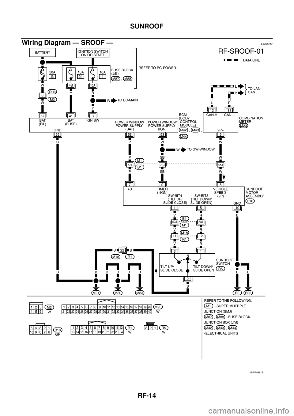
Wiring Diagram — SROOF —
EIS00D4Z
MIWA0481E
Page 2692 of 3171
SUNROOF
RF-15
C
D
E
F
G
H
J
K
L
MA
B
RF
Terminals and Reference Value for BCMEIS00D50
Terminals and Reference Value for Sunroof Motor AssemblyEIS00D51
Te r m i -
nalWire
colorItem ConditionVo l ta g e (V )
(Approx.)
3 Y Ignition switch (ON) Ignition switch (ON or START) position Battery voltage
41 Y Power source (Fuse) — Battery voltage
53 W Power window power supply (IGN)Ignition switch ON Battery voltage
Other than above 0
55 B Ground — 0
57 W Power source (Fusible link) — Battery voltage
58 P Power window power supply (BAT) — Battery voltage
Te r -
minalWire
colorItem ConditionVoltage (V)
(Approx.)
1VSunroof (Tilt up/Slide close)
switch signalIgnition switch ON and sunroof switch in
TILT UP / SLIDE CLOSE position0
Other than above Battery voltage
5RSunroof (Tilt down/Slide
open) switch signalIgnition switch ON and sunroof switch in
TILT DOWN / SLIDE OPEN position0
Other than above Battery voltage
7 P Power window power supply — Battery voltage
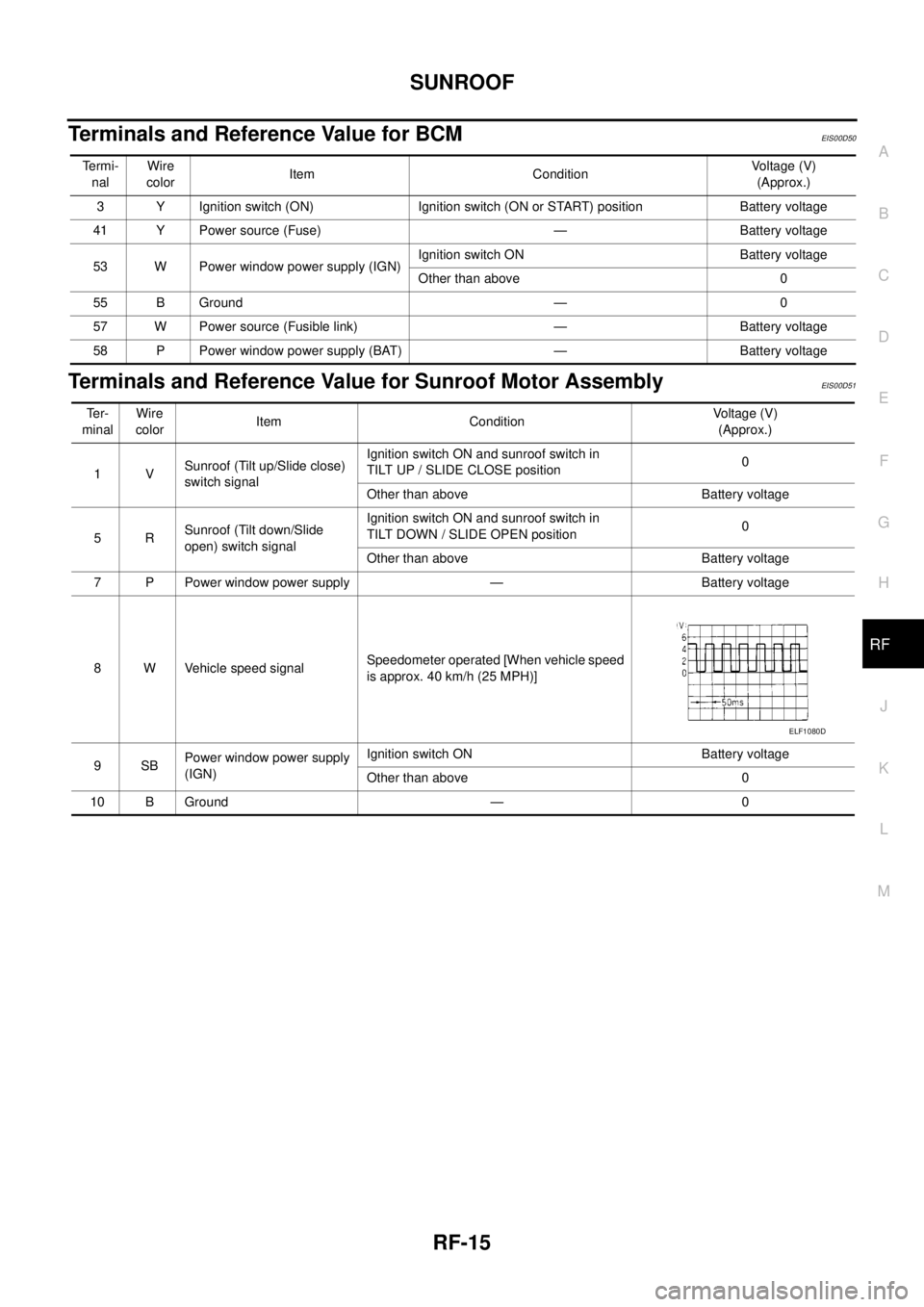
8 W Vehicle speed signalSpeedometer operated [When vehicle speed
is approx. 40 km/h (25 MPH)]
9SBPower window power supply
(IGN)Ignition switch ON Battery voltage
Other than above 0
10 B Ground — 0
ELF1080D
Page 2693 of 3171
RF-16
SUNROOF
Work Flow
EIS00D52
1. Check the symptom and customer's requests.
2. Understand the outline of system. Refer toRF-11, "
System Description".
3. According to the trouble diagnosis chart, repair or replace the cause of the malfunction. Refer toRF-16,
"Trouble Diagnosis Symptom Chart".
4. Does sunroof system operate normally? If Yes, GO TO 5. If No, GO TO 3.
5. INSPECTION END.
Trouble Diagnosis Symptom ChartEIS00D53
BCM Power Supply and Ground Circuit CheckEIS00D54
1.FUSE INSPECTION
Check the following.
l50A fusible link (letterG, located in the fuse and fusible link box)
l10A fuse [No. 1, located in the fuse block (J/B)]
l10A fuse [No.21 located in the fuse block (J/B)]
NOTE:
Refer toRF-10, "
Component Parts and Harness Connector Location".
OK or NG
OK >> GO TO 2.
NG >> If fuse is blown, be sure to eliminate cause of malfunction before installing new fuse, refer toPG-
4, "POWER SUPPLY ROUTING CIRCUIT".
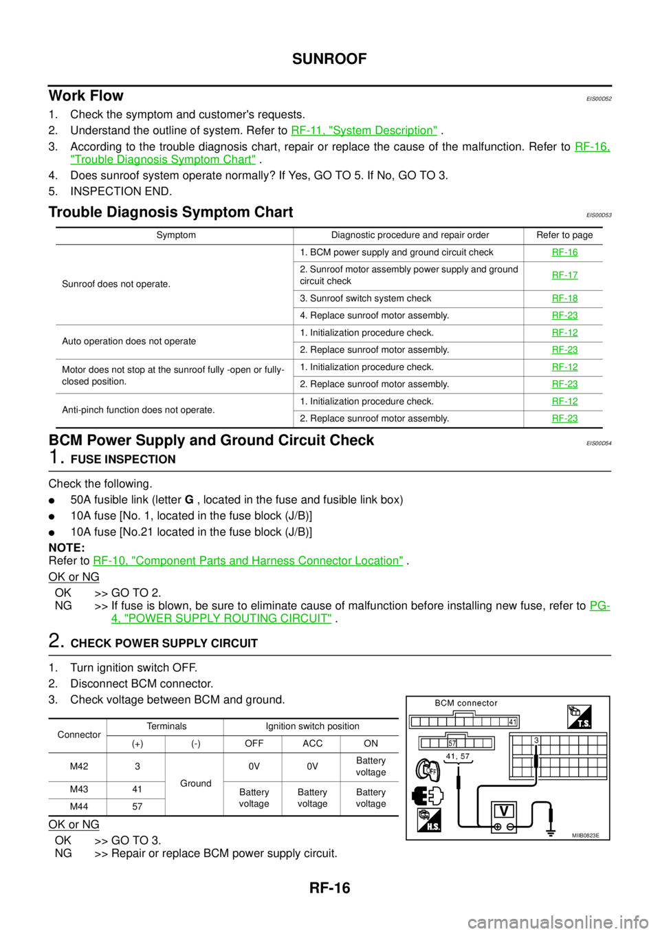
2.CHECK POWER SUPPLY CIRCUIT
1. Turn ignition switch OFF.
2. Disconnect BCM connector.
3. Check voltage between BCM and ground.
OK or NG
OK >> GO TO 3.
NG >> Repair or replace BCM power supply circuit.
Symptom Diagnostic procedure and repair order Refer to page
Sunroof does not operate.1. BCM power supply and ground circuit checkRF-16
2. Sunroof motor assembly power supply and ground
circuit checkRF-17
3. Sunroof switch system checkRF-18
4. Replace sunroof motor assembly.RF-23
Auto operation does not operate1. Initialization procedure check.RF-122. Replace sunroof motor assembly.RF-23
Motor does not stop at the sunroof fully -open or fully-
closed position.1. Initialization procedure check.RF-12
2. Replace sunroof motor assembly.RF-23
Anti-pinch function does not operate.1. Initialization procedure check.RF-122. Replace sunroof motor assembly.RF-23
ConnectorTerminals Ignition switch position
(+) (-) OFF ACC ON
M42 3
Ground0V 0VBattery
voltage
M43 41
Battery
voltageBattery
voltageBattery
voltage
M44 57
MIIB0823E
Page 2694 of 3171
SUNROOF
RF-17
C
D
E
F
G
H
J
K
L
MA
B
RF
3.CHECK GROUND CIRCUIT
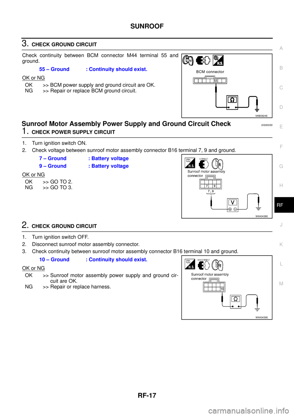
Check continuity between BCM connector M44 terminal 55 and
ground.
OK or NG
OK >> BCM power supply and ground circuit are OK.
NG >> Repair or replace BCM ground circuit.
Sunroof Motor Assembly Power Supply and Ground Circuit CheckEIS00D55
1.CHECK POWER SUPPLY CIRCUIT
1. Turn ignition switch ON.
2. Check voltage between sunroof motor assembly connector B16 terminal 7, 9 and ground.
OK or NG
OK >> GO TO 2.
NG >> GO TO 3.
2.CHECK GROUND CIRCUIT
1. Turn ignition switch OFF.
2. Disconnect sunroof motor assembly connector.
3. Check continuity between sunroof motor assembly connector B16 terminal 10 and ground.
OK or NG
OK >> Sunroof motor assembly power supply and ground cir-
cuit are OK.
NG >> Repair or replace harness.55 – Ground : Continuity should exist.
MIIB0824E
7 – Ground : Battery voltage
9 – Ground : Battery voltage
WIIA0438E
10 – Ground : Continuity should exist.
WIIA0439E