2005 NISSAN NAVARA power steering belt
[x] Cancel search: power steering beltPage 2628 of 3171
PS-1
POWER STEERING SYSTEM
G STEERING
CONTENTS
C
D
E
F
H
I
J
K
L
M
SECTIONPS
A
B
PS
POWER STEERING SYSTEM
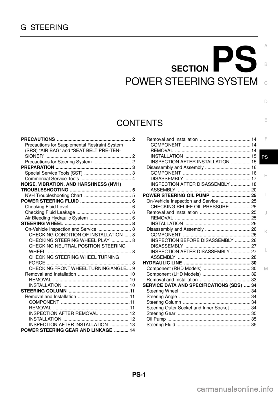
PRECAUTIONS .......................................................... 2
Precautions for Supplemental Restraint System
(SRS)“AIRBAG”and“SEATBELTPRE-TEN-
SIONER” .................................................................. 2
Precautions for Steering System .............................. 2
PREPARATION ........................................................... 3
Special Service Tools [SST] ..................................... 3
Commercial Service Tools ........................................ 4
NOISE, VIBRATION, AND HARSHNESS (NVH)
TROUBLESHOOTING ................................................ 5
NVH Troubleshooting Chart ..................................... 5
POWER STEERING FLUID ........................................ 6
Checking Fluid Level ................................................ 6
Checking Fluid Leakage ........................................... 6
Air Bleeding Hydraulic System ................................. 6
STEERING WHEEL .................................................... 8
On-Vehicle Inspection and Service .......................... 8
CHECKING CONDITION OF INSTALLATION ...... 8
CHECKING STEERING WHEEL PLAY ................ 8
CHECKING NEUTRAL POSITION STEERING
WHEEL ................................................................. 8
CHECKING STEERING WHEEL TURNING
FORCE .................................................................. 8
CHECKING FRONT WHEEL TURNING ANGLE..... 9
Removal and Installation ........................................ 10
REMOVAL ........................................................... 10
INSTALLATION ................................................... 10
STEERING COLUMN ................................................11
Removal and Installation ......................................... 11
COMPONENT ...................................................... 11
REMOVAL ............................................................ 11
INSPECTION AFTER REMOVAL ....................... 12
INSTALLATION ................................................... 12
INSPECTION AFTER INSTALLATION ............... 13
POWER STEERING GEAR AND LINKAGE ............ 14Removal and Installation ........................................ 14
COMPONENT ..................................................... 14
REMOVAL ........................................................... 14
INSTALLATION ................................................... 15
INSPECTION AFTER INSTALLATION ................ 15
Disassembly and Assembly .................................... 16
COMPONENT ..................................................... 16
DISASSEMBLY ................................................... 17
INSPECTION AFTER DISASSEMBLY ................ 18
ASSEMBLY ......................................................... 20
POWER STEERING OIL PUMP ............................... 25
On-Vehicle Inspection and Service ......................... 25
CHECKING RELIEF OIL PRESSURE ................ 25
Removal and Installation ........................................ 25
REMOVAL ........................................................... 25
INSTALLATION ................................................... 26
Disassembly and Assembly .................................... 26
COMPONENT ..................................................... 26
INSPECTION BEFORE DISASSEMBLY ............. 26
DISASSEMBLY ................................................... 27
INSPECTION AFTER DISASSEMBLY ................ 27
ASSEMBLY ......................................................... 28
HYDRAULIC LINE .................................................... 30
Component (RHD Models) ..................................... 30
Component (LHD Models) ...................................... 32
Removal and Installation ........................................ 33
SERVICE DATA AND SPECIFICATIONS (SDS) ...... 34
Steering Wheel ....................................................... 34
Steering Angle ........................................................ 34
Steering Column ..................................................... 34
Steering Outer Socket and Inner Socket ................ 34
Steering Gear ......................................................... 35
Oil Pump ................................................................. 35
Steering Fluid .......................................................... 35
Page 2652 of 3171
POWER STEERING OIL PUMP
PS-25
C
D
E
F
H
I
J
K
L
MA
B
PS
POWER STEERING OIL PUMPPFP:49110
On-Vehicle Inspection and ServiceEGS001LL
CHECKING RELIEF OIL PRESSURE
CAUTION:
Make sure that belt tension is normal before starting the following procedure.
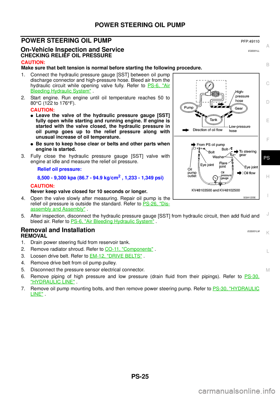
1. Connect the hydraulic pressure gauge [SST] between oil pump
discharge connector and high-pressure hose. Bleed air from the
hydraulic circuit while opening valve fully. Refer toPS-6, "
Air
Bleeding Hydraulic System".
2. Start engine. Run engine until oil temperature reaches 50 to
80°C(122to176°F).
CAUTION:
lLeave the valve of the hydraulic pressure gauge [SST]
fully open while starting and running engine. If engine is
started with the valve closed, the hydraulic pressure in
oil pump goes up to the relief pressure along with
unusual increase of oil temperature.
lBe sure to keep hose clear or belts and other parts when
engineisstarted.
3. Fully close the hydraulic pressure gauge [SST] valve with
engine at idle and measure the relief oil pressure.
CAUTION:
Never keep valve closed for 10 seconds or longer.
4. Open the valve slowly after measuring. Repair oil pump is the
relief oil pressure is outside the standard. Refer toPS-26, "
Dis-
assembly and Assembly".
5. After inspection, disconnect the hydraulic pressure gauge [SST] from hydraulic circuit, then add fluid and
bleed air. Refer toPS-6, "
Air Bleeding Hydraulic System".
Removal and InstallationEGS001LM
REMOVAL
1. Drain power steering fluid from reservoir tank.
2. Remove radiator shroud. Refer toCO-11, "
Components".
3. Loosen drive belt. Refer toEM-12, "
DRIVE BELTS".
4. Remove drive belt from oil pump pulley.
5. Disconnect the pressure sensor electrical connector.
6. Remove piping of high pressure and low pressure (drain fluid from their pipings). Refer toPS-30,
"HYDRAULIC LINE".
7. Remove oil pump mounting bolts, and then remove power steering pump. Refer toPS-30, "
HYDRAULIC
LINE". Relief oil pressure:
8,500 - 9,300 kpa (86.7 - 94.9 kg/cm
2, 1,233 - 1,349 psi)
SGIA1225E
Page 2653 of 3171
PS-26
POWER STEERING OIL PUMP
INSTALLATION
Installation is the reverse order of removal. For tightening torque, refer toPS-30, "HYDRAULIC LINE".
lPerform the following procedure after installing.
–Adjust belt tension. Refer toEM-12, "DRIVE BELTS".
–Bleed air. Refer toPS-6, "Air Bleeding Hydraulic System".
Disassembly and AssemblyEGS001LN
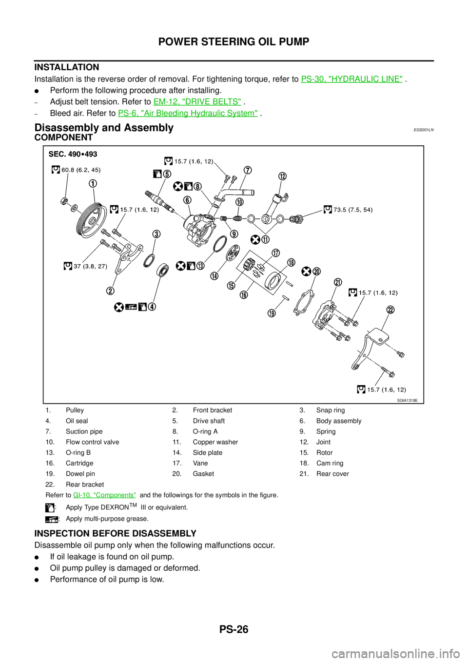
COMPONENT
INSPECTION BEFORE DISASSEMBLY
Disassemble oil pump only when the following malfunctions occur.
lIf oil leakage is found on oil pump.
lOil pump pulley is damaged or deformed.
lPerformance of oil pump is low.
1. Pulley 2. Front bracket 3. Snap ring
4. Oil seal 5. Drive shaft 6. Body assembly
7. Suction pipe 8. O-ring A 9. Spring
10. Flow control valve 11. Copper washer 12. Joint
13. O-ring B 14. Side plate 15. Rotor
16. Cartridge 17. Vane 18. Cam ring
19. Dowel pin 20. Gasket 21. Rear cover
22. Rear bracket
Referr toGI-10, "
Components"and the followings for the symbols in the figure.
:
Apply Type DEXRON
TMIII or equivalent.
:Apply multi-purpose grease.
SGIA1318E
Page 2912 of 3171
PRECAUTIONS
SRS-3
C
D
E
F
G
I
J
K
L
MA
B
SRS
PRECAUTIONSPFP:00001
Precautions for Supplemental Restraint System (SRS) “AIR BAG” and “SEAT
BELT PRE-TENSIONER”
EHS001Y8
The Supplemental Restraint System such as “AIR BAG” and “SEAT BELT PRE-TENSIONER”, used along
with a front seat belt, helps to reduce the risk or severity of injury to the driver and front passenger for certain
types of collision. Information necessary to service the system safely is included in the SRS and SB section of
this Service Manual.
WARNING:
lTo avoid rendering the SRS inoperative, which could increase the risk of personal injury or death
in the event of a collision which would result in air bag inflation, all maintenance must be per-
formed by an authorized NISSAN/INFINITI dealer.
lImproper maintenance, including incorrect removal and installation of the SRS, can lead to per-
sonal injury caused by unintentional activation of the system. For removal of Spiral Cable and Air
Bag Module, see the SRS section.
lDo not use electrical test equipment on any circuit related to the SRS unless instructed to in this
Service Manual. SRS wiring harnesses can be identified by yellow and/or orange harnesses or
harness connectors.
Precautions for SRS “AIR BAG” and “SEAT BELT PRE-TENSIONER” ServiceEHS001Y9
lDo not use electrical test equipment to check SRS circuits unless instructed to in this Service Manual.
lBefore servicing the SRS, turn ignition switch OFF, disconnect both battery cables and wait at least 3 min-
utes.
For approximately 3 minutes after the cables are removed, it is still possible for the air bag and seat belt
pre-tensioner to deploy. Therefore, do not work on any SRS connectors or wires until at least 3 minutes
have passed.
lDiagnosis sensor unit must always be installed with their arrow marks “Ü” pointing towards the front of the
vehicle for proper operation. Also check diagnosis sensor unit for cracks, deformities or rust before instal-
lation and replace as required.
lThe spiral cable must be aligned with the neutral position since its rotations are limited. Do not attempt to
turn steering wheel or column after removal of steering gear.
lHandle air bag module carefully. Always place driver and front passenger air bag modules with the pad
side facing upward and place front side air bag module standing with stud bolt side setting bottom.
lConduct self-diagnosis to check entire SRS for proper function after replacing any components.
lAfter air bag inflates, the front instrument panel assembly should be replaced if damaged.
lAlways replace instrument panel pad following front passenger air bag deployment.
Precautions for Trouble DiagnosisEHS001YA
When you read wiring diagrams, refer to the following:
lGI-15, "How to Read Wiring Diagrams"in GI section
lPG-4, "POWER SUPPLY ROUTING CIRCUIT"in PG section
When you perform trouble diagnosis, refer to the following:
lGI-11, "How to Follow Trouble Diagnoses"in GI section
lGI-24, "How to Perform Efficient Diagnosis for an Electrical Incident"in GI section
Check for any service bulletins before servicing the vehicle.