2005 NISSAN NAVARA low beam
[x] Cancel search: low beamPage 2144 of 3171

AUTO LIGHT SYSTEM
LT-61
C
D
E
F
G
H
I
J
L
MA
B
LT
Display Item List
NOTE:
This item is displayed, but cannot be monitored.
ACTIVE TEST
Operation Procedure
1. Touch “HEAD LAMP” on “SELECT TEST ITEM” screen.
2. Touch “ACTIVE TEST” on “SELECT DIAG MODE” screen.
3. Touch item to be tested and check operation of the selected item.
4. During the operation check, touching “OFF” deactivates the operation.
Display Item List
Monitor item Contents
IGN ON SW “ON/OFF”Displays status (ignition switch IGN position: ON/other: OFF) of ignition switch judged from
the ignition switch signal.
ACC ON SW “ON/OFF”Displays status (ignition switch ACC or IGN position: ON/other: OFF) of ignition switch judged
from the ignition switch signal.
HI BEAM SW “ON/OFF”Displays status (lighting switch high beam position: ON/other: OFF) of high beam switch
judged from the lighting switch signal.
HEAD LAMP SW 1 “ON/OFF”Displays status (lighting switch 2ND position: ON/other: OFF) of headlamp 1 switch judged
from the lighting switch signal.
HEAD LAMP SW 2 “ON/OFF”Displays status (lighting switch 2ND position: ON/other: OFF) of headlamp 2 switch judged
from the lighting switch signal.
LIGHT SW 1ST “ON/OFF”Displays status (lighting switch 1ST or 2ND position: ON/other: OFF) of lighting switch 1ST
position switch judged from the lighting switch signal.
PASSING SW “ON/OFF”Displays status (lighting switch passing position: ON/other: OFF) of passing switch judged
from the lighting switch signal.
FR FOG SW “ON/OFF”Displays status (lighting switch front fog lamp ON position: ON/others: OFF) of front fog lamp
switch judged from the lighting switch signal.
RR FOG SW “ON/OFF”Displays status (lighting switch rear fog lamp ON position: ON/others: OFF) of rear fog lamp
switch judged from the lighting switch signal.
DOOR SW - DR “ON/OFF”Displays status (door is open: ON/door is closed: OFF) of driver side door switch judged from
the driver side door switch signal.
DOOR SW - AS “ON/OFF”Displays status (door is open: ON/door is closed: OFF) of passenger side door switch judged
from the passenger side door switch signal.
DOOR SW - RR “ON/OFF”Displays status (door is open: ON/door is closed: OFF) of rear door switch (RH) judged from
the rear door switch (RH) signal.
DOOR SW - RL “ON/OFF”Displays status (door is open: ON/door is closed: OFF) of rear door switch (LH) judged from
the rear door switch (LH) signal.
BACK DOOR SW “ON/OFF”Displays status (door is open: ON/door is closed: OFF) of back door switch judged from the
back door switch signal.
TURN SIGNAL R “ON/OFF”Displays status (turn signal switch right position: ON/other: OFF) of turn RH switch judged
from the turn signal switch signal.
TURN SIGNAL L “ON/OFF”Displays status (turn signal switch left position: ON/other: OFF) of turn LH switch judged from
the turn signal switch signal.
CARGO LAMP SW
NOTE“OFF” —
HD LIGHT TIMER“10 sec/
30 sec”Displays status (MODE 1: 10 sec./ MODE 2: 30 sec.) of head light timer.
LIT-SEN FAIL
NOTE“OK” —
AUT LIGHT SYS
NOTE“OFF” —
Test item Description
TAIL LAMP Allows tail lamp relay to operate by switching ON-OFF.
HEAD LAMP Allows headlamp relay (HI, LO) to operate by switching ON-OFF.
Page 2154 of 3171
FRONT FOG LAMP
LT-71
C
D
E
F
G
H
I
J
L
MA
B
LT
FRONT FOG LAMPPFP:26150
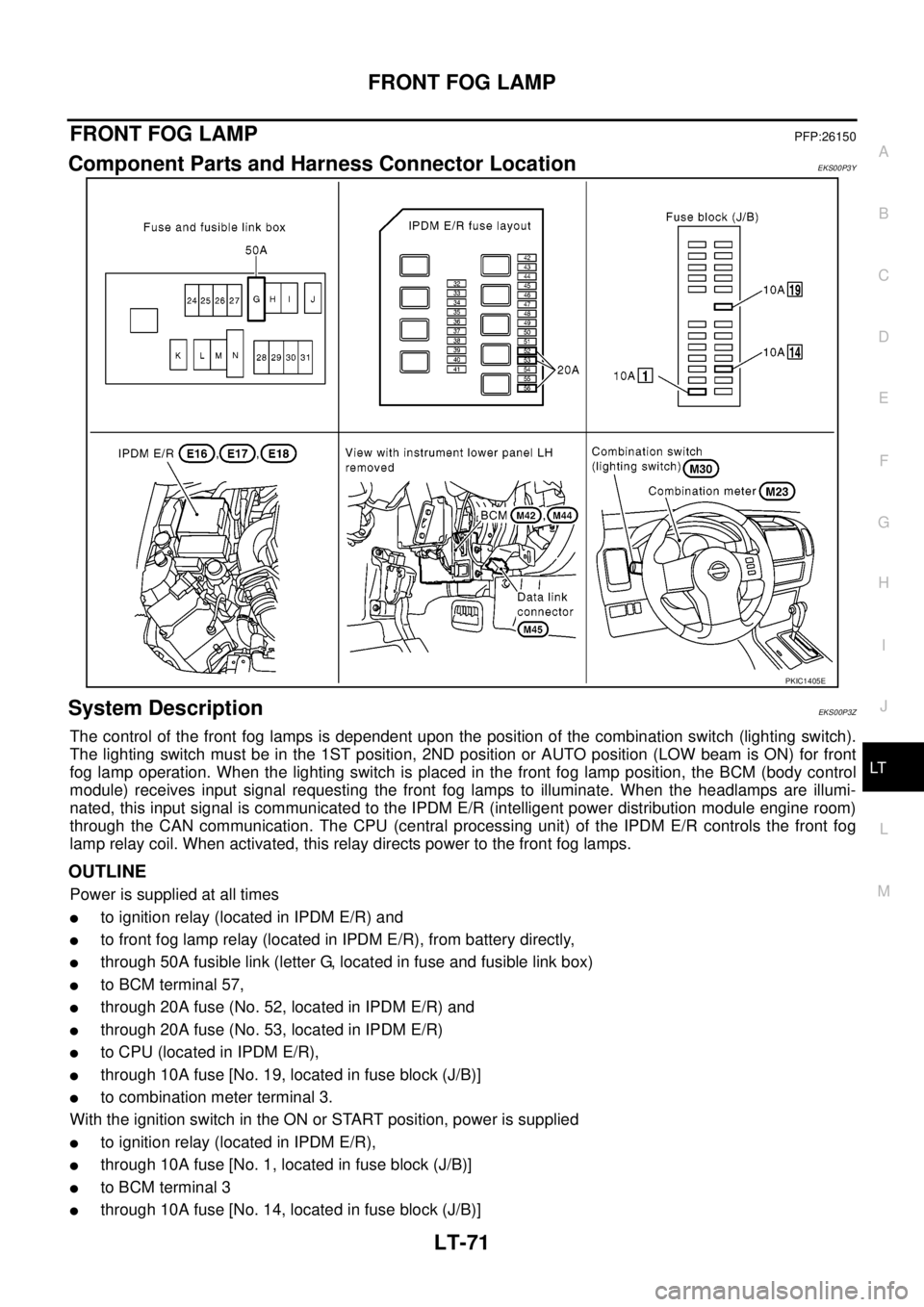
Component Parts and Harness Connector LocationEKS00P3Y
System DescriptionEKS00P3Z
The control of the front fog lamps is dependent upon the position of the combination switch (lighting switch).
The lighting switch must be in the 1ST position, 2ND position or AUTO position (LOW beam is ON) for front
fog lamp operation. When the lighting switch is placed in the front fog lamp position, the BCM (body control
module) receives input signal requesting the front fog lamps to illuminate. When the headlamps are illumi-
nated, this input signal is communicated to the IPDM E/R (intelligent power distribution module engine room)
through the CAN communication. The CPU (central processing unit) of the IPDM E/R controls the front fog
lamp relay coil. When activated, this relay directs power to the front fog lamps.
OUTLINE
Power is supplied at all times
lto ignition relay (located in IPDM E/R) and
lto front fog lamp relay (located in IPDM E/R), from battery directly,
lthrough 50A fusible link (letter G, located in fuse and fusible link box)
lto BCM terminal 57,
lthrough 20A fuse (No. 52, located in IPDM E/R) and
lthrough 20A fuse (No. 53, located in IPDM E/R)
lto CPU (located in IPDM E/R),
lthrough 10A fuse [No. 19, located in fuse block (J/B)]
lto combination meter terminal 3.
With the ignition switch in the ON or START position, power is supplied
lto ignition relay (located in IPDM E/R),
lthrough 10A fuse [No. 1, located in fuse block (J/B)]
lto BCM terminal 3
lthrough 10A fuse [No. 14, located in fuse block (J/B)]
PKIC1405E
Page 2155 of 3171

LT-72
FRONT FOG LAMP
lto combination meter terminal 16.
Ground is supplied
lto BCM terminal 55 and
lto combination meter terminal 23
lthrough grounds M21, M80 and M83,
lto IPDM E/R terminals 38 and 59
lthrough grounds E21, E41 and E61.
FOG LAMP OPERATION
The front fog lamp switch is built into the combination switch. The lighting switch must be in the 1ST position,
2ND position or AUTO position (LOW beam is ON) and the front fog lamp switch must be ON for front fog lamp
operation.
With the front fog lamp switch in the ON position, the CPU of the IPDM E/R grounds the coil side of the front
fog lamp relay. The front fog lamp relay then directs power
lthrough 20A fuse (No. 56, located in IPDM E/R)
lthrough IPDM E/R terminal 50
lto front fog lamp LH terminal 1 and
lthrough IPDM E/R terminal 51
lto front fog lamp RH terminal 1.
Ground is supplied at all times
lto front fog lamp RH and LH terminal 2
lthrough grounds E21, E41 and E61.
With power and ground supplied, the front fog lamps illuminate.
COMBINATION SWITCH READING FUNCTION
Refer toBCS-3, "COMBINATION SWITCH READING FUNCTION".
CAN Communication System DescriptionEKS00P40
Refer toLAN-23, "CAN COMMUNICATION".
Page 2160 of 3171
FRONT FOG LAMP
LT-77
C
D
E
F
G
H
I
J
L
MA
B
LT
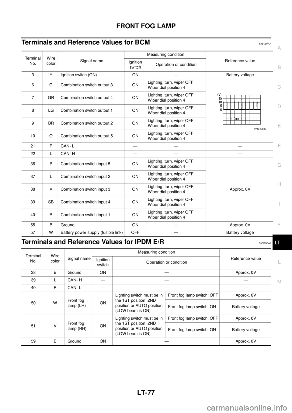
Terminals and Reference Values for BCMEKS00P43
Terminals and Reference Values for IPDM E/REKS00P44
Te r m i n a l
No.Wire
colorSignal nameMeasuring condition
Reference value
Ignition
switchOperation or condition
3 Y Ignition switch (ON) ON — Battery voltage
6 G Combination switch output 3 ONLighting, turn, wiper OFF
Wiper dial position 4
7 GR Combination switch output 4 ONLighting, turn, wiper OFF
Wiper dial position 4
8 LG Combination switch output 1 ONLighting, turn, wiper OFF
Wiper dial position 4
9 BR Combination switch output 2 ONLighting, turn, wiper OFF
Wiper dial position 4
10 O Combination switch output 5 ONLighting, turn, wiper OFF
Wiper dial position 4
21 P CAN- L — — —
22 L CAN- H — — —
36 P Combination switch input 5 ONLighting, turn, wiper OFF
Wiper dial position 4
Approx. 0V 37 L Combination switch input 2 ONLighting, turn, wiper OFF
Wiper dial position 4
38 V Combination switch input 3 ONLighting, turn, wiper OFF
Wiper dial position 4
39 SB Combination switch input 4 ONLighting, turn, wiper OFF
Wiper dial position 4
40 R Combination switch input 1 ONLighting, turn, wiper OFF
Wiper dial position 4
55 B Ground ON — Approx. 0V
57 W Battery power supply (fusible link) OFF — Battery voltage
PKIB4958J
Terminal
No.Wire
colorSignal nameMeasuring condition
Reference value
Ignition
switchOperation or condition
38 B Ground ON — Approx. 0V
39 L CAN- H — — —
40 P CAN- L — — —
50 WFront fog
lamp (LH)ONLighting switch must be in
the 1ST position, 2ND
position or AUTO position
(LOW beam is ON)Front fog lamp switch: OFF Approx. 0V
Front fog lamp switch: ON Battery voltage
51 VFront fog
lamp (RH)ONLighting switch must be in
the 1ST position, 2ND
position or AUTO position
(LOW beam is ON)Front fog lamp switch: OFF Approx. 0V
Front fog lamp switch: ON Battery voltage
59 B Ground ON — Approx. 0V
Page 2168 of 3171
FRONT FOG LAMP
LT-85
C
D
E
F
G
H
I
J
L
MA
B
LT
Aiming AdjustmentEKS00P4D
The fog lamp is a semi-sealed beam type which uses a replaceable halogen bulb. Before performing aiming
adjustment, make sure of the following.
lKeep all tires inflated to correct pressure.
lPlace vehicle on level surface.
lSee that vehicle is unloaded (except for full levels of coolant, engine oil and fuel, and spare tire, jack, and
tools). Have the driver or equivalent weight placed in driver's seat.
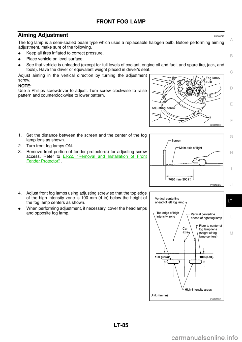
Adjust aiming in the vertical direction by turning the adjustment
screw.
NOTE:
Use a Phillips screwdriver to adjust. Turn screw clockwise to raise
pattern and counterclockwise to lower pattern.
1. Set the distance between the screen and the center of the fog
lamp lens as shown.
2. Turn front fog lamps ON.
3. Remove front portion of fender protector(s) for adjusting screw
access. Refer toEI-22, "
Removal and Installation of Front
Fender Protector".
4. Adjust front fog lamps using adjusting screw so that the top edge
of the high intensity zone is 100 mm (4 in) below the height of
the fog lamp centers as shown.
lWhen performing adjustment, if necessary, cover the headlamps
and opposite fog lamp.
SKIB6539E
PKIB1672E
PKIB1673E
Page 2170 of 3171
REAR FOG LAMP
LT-87
C
D
E
F
G
H
I
J
L
MA
B
LT
REAR FOG LAMPPFP:26550
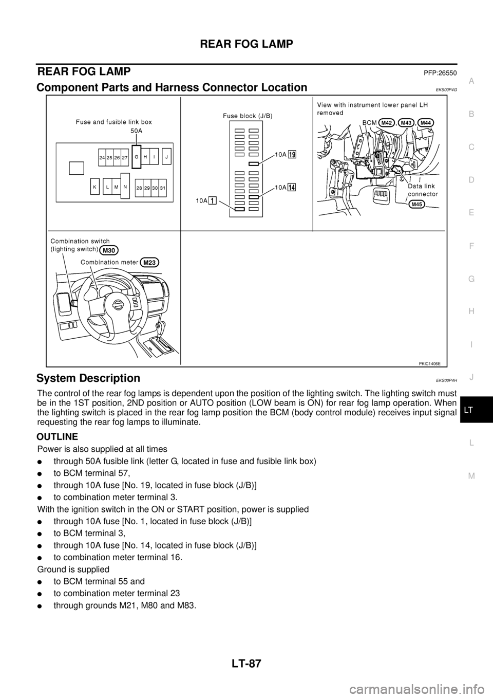
Component Parts and Harness Connector LocationEKS00P4G
System DescriptionEKS00P4H
The control of the rear fog lamps is dependent upon the position of the lighting switch. The lighting switch must
be in the 1ST position, 2ND position or AUTO position (LOW beam is ON) for rear fog lamp operation. When
the lighting switch is placed in the rear fog lamp position the BCM (body control module) receives input signal
requesting the rear fog lamps to illuminate.
OUTLINE
Power is also supplied at all times
lthrough 50A fusible link (letter G, located in fuse and fusible link box)
lto BCM terminal 57,
lthrough 10A fuse [No. 19, located in fuse block (J/B)]
lto combination meter terminal 3.
With the ignition switch in the ON or START position, power is supplied
lthrough 10A fuse [No. 1, located in fuse block (J/B)]
lto BCM terminal 3,
lthrough 10A fuse [No. 14, located in fuse block (J/B)]
lto combination meter terminal 16.
Ground is supplied
lto BCM terminal 55 and
lto combination meter terminal 23
lthrough grounds M21, M80 and M83.
PKIC1406E
Page 2171 of 3171

LT-88
REAR FOG LAMP
REAR FOG LAMP OPERATION
The lighting switch must be in the 1ST position, 2ND position or AUTO position (LOW beam is ON) for rear fog
lamp operation.
With the rear fog lamp switch in the ON position, the BCM directs power
lthrough BCM terminal 49
lto rear combination lamp LH terminal 6 (LHD models)
lto rear combination lamp RH terminal 6 (RHD models).
Ground is supplied
lto rear combination lamp RH and LH terminals 3
lthrough grounds E21, E41 and E61.
With power and ground supplied, the rear fog lamps illuminate.
COMBINATION SWITCH READING FUNCTION
Refer toBCS-3, "COMBINATION SWITCH READING FUNCTION".
CAN Communication System DescriptionEKS00P4I
Refer toLAN-23, "CAN COMMUNICATION".
CAN Communication UnitEKS00P4J
Refer toLAN-30, "CAN Communication Unit".
Page 2199 of 3171
LT-116
COMBINATION SWITCH
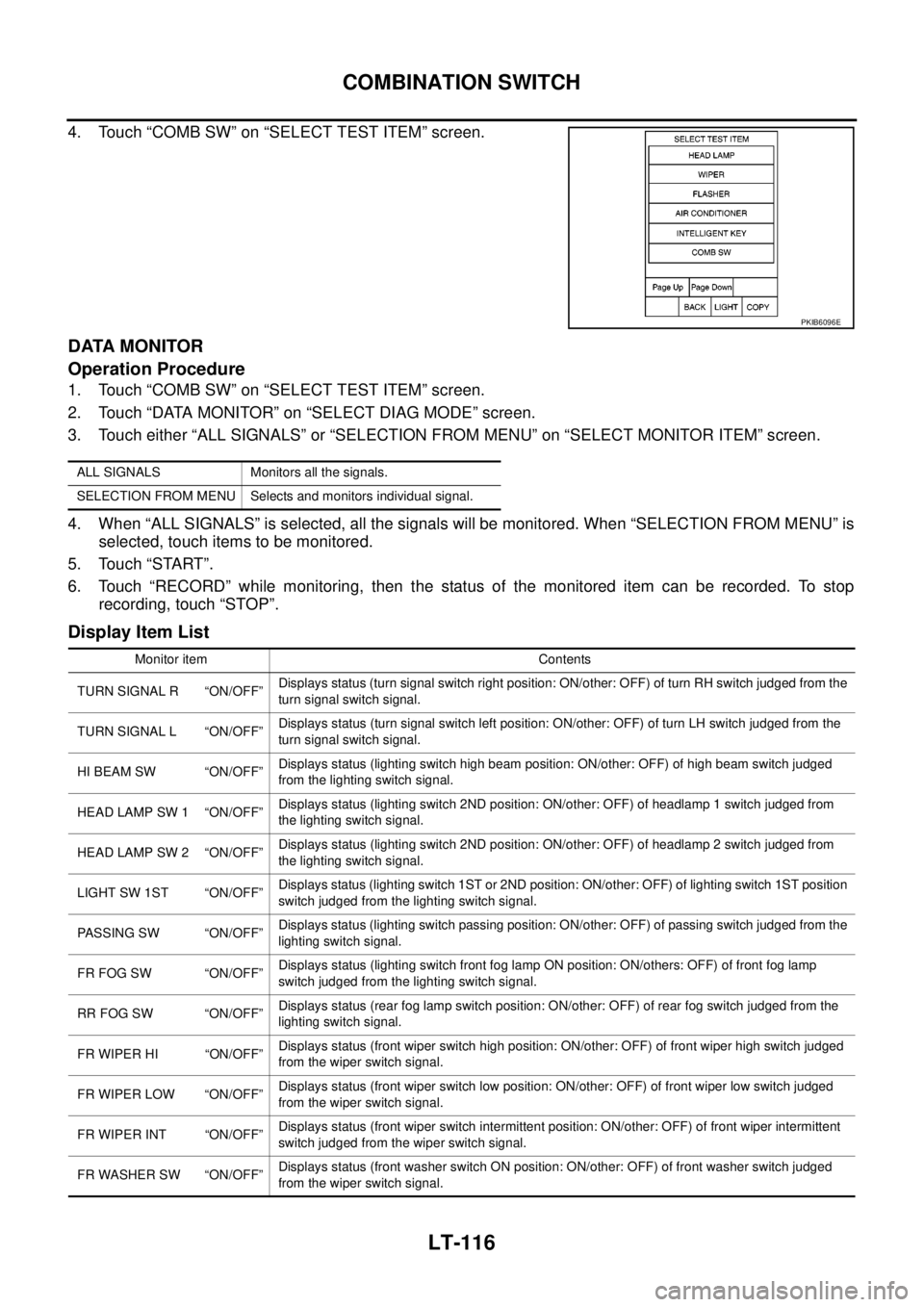
4. Touch “COMB SW” on “SELECT TEST ITEM” screen.
DATA MONITOR
Operation Procedure
1. Touch “COMB SW” on “SELECT TEST ITEM” screen.
2. Touch “DATA MONITOR” on “SELECT DIAG MODE” screen.
3. Touch either “ALL SIGNALS” or “SELECTION FROM MENU” on “SELECT MONITOR ITEM” screen.
4. When “ALL SIGNALS” is selected, all the signals will be monitored. When “SELECTION FROM MENU” is
selected, touch items to be monitored.
5. Touch “START”.
6. Touch “RECORD” while monitoring, then the status of the monitored item can be recorded. To stop
recording, touch “STOP”.
Display Item List
PKIB6096E
ALL SIGNALS Monitors all the signals.
SELECTION FROM MENU Selects and monitors individual signal.
Monitor item Contents
TURN SIGNAL R “ON/OFF”Displays status (turn signal switch right position: ON/other: OFF) of turn RH switch judged from the
turn signal switch signal.
TURN SIGNAL L “ON/OFF”Displays status (turn signal switch left position: ON/other: OFF) of turn LH switch judged from the
turn signal switch signal.
HI BEAM SW “ON/OFF”Displays status (lighting switch high beam position: ON/other: OFF) of high beam switch judged
from the lighting switch signal.
HEAD LAMP SW 1 “ON/OFF”Displays status (lighting switch 2ND position: ON/other: OFF) of headlamp 1 switch judged from
the lighting switch signal.
HEAD LAMP SW 2 “ON/OFF”Displays status (lighting switch 2ND position: ON/other: OFF) of headlamp 2 switch judged from
the lighting switch signal.
LIGHT SW 1ST “ON/OFF”Displays status (lighting switch 1ST or 2ND position: ON/other: OFF) of lighting switch 1ST position
switch judged from the lighting switch signal.
PASSING SW “ON/OFF”Displays status (lighting switch passing position: ON/other: OFF) of passing switch judged from the
lighting switch signal.
FR FOG SW “ON/OFF”Displays status (lighting switch front fog lamp ON position: ON/others: OFF) of front fog lamp
switch judged from the lighting switch signal.
RR FOG SW “ON/OFF”Displays status (rear fog lamp switch position: ON/other: OFF) of rear fog switch judged from the
lighting switch signal.
FR WIPER HI “ON/OFF”Displays status (front wiper switch high position: ON/other: OFF) of front wiper high switch judged
from the wiper switch signal.
FR WIPER LOW “ON/OFF”Displays status (front wiper switch low position: ON/other: OFF) of front wiper low switch judged
from the wiper switch signal.
FR WIPER INT “ON/OFF”Displays status (front wiper switch intermittent position: ON/other: OFF) of front wiper intermittent
switch judged from the wiper switch signal.
FR WASHER SW “ON/OFF”Displays status (front washer switch ON position: ON/other: OFF) of front washer switch judged
from the wiper switch signal.