Page 2201 of 3171

LT-118
COMBINATION SWITCH
Combination Switch Inspection
EKS00P9Y
1.SYSTEM CHECK
Referring to table below, check to which system the malfunctioning switch belongs.
>> GO TO 2.
2.SYSTEM CHECK
With CONSULT-II
CAUTION:
If CONSULT-II is used with no connection of CONSULT-II CONVERTER, malfunctions might be
detected in self-diagnosis depending on control unit which carry out CAN communication.
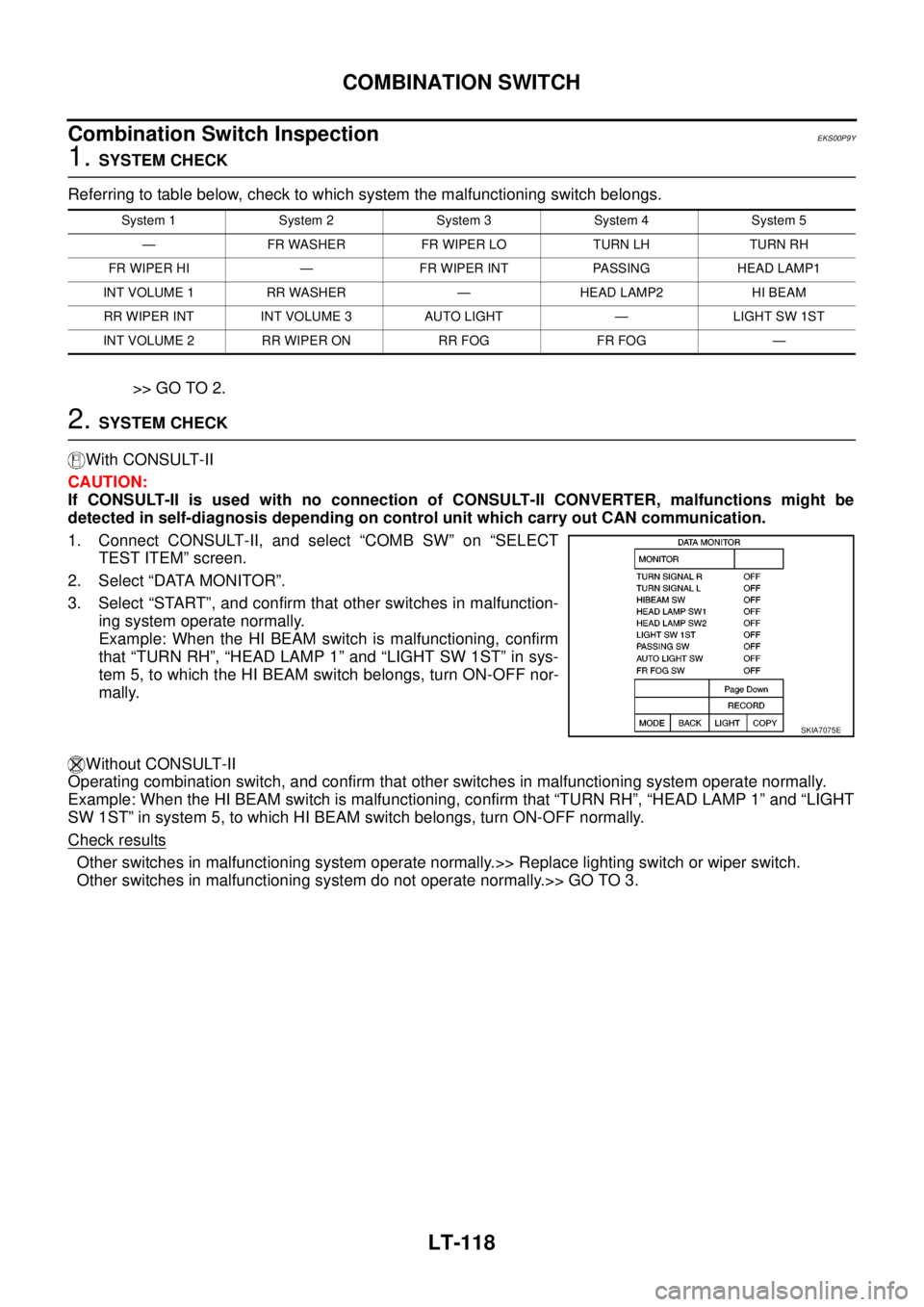
1. Connect CONSULT-II, and select “COMB SW” on “SELECT
TEST ITEM” screen.
2. Select “DATA MONITOR”.
3. Select “START”, and confirm that other switches in malfunction-
ing system operate normally.
Example: When the HI BEAM switch is malfunctioning, confirm
that “TURN RH”, “HEAD LAMP 1” and “LIGHT SW 1ST” in sys-
tem 5, to which the HI BEAM switch belongs, turn ON-OFF nor-
mally.
Without CONSULT-II
Operating combination switch, and confirm that other switches in malfunctioning system operate normally.
Example: When the HI BEAM switch is malfunctioning, confirm that “TURN RH”, “HEAD LAMP 1” and “LIGHT
SW 1ST” in system 5, to which HI BEAM switch belongs, turn ON-OFF normally.
Check results
Other switches in malfunctioning system operate normally.>> Replace lighting switch or wiper switch.
Other switches in malfunctioning system do not operate normally.>> GO TO 3.
System 1 System 2 System 3 System 4 System 5
— FR WASHER FR WIPER LO TURN LH TURN RH
FR WIPER HI — FR WIPER INT PASSING HEAD LAMP1
INT VOLUME 1 RR WASHER — HEAD LAMP2 HI BEAM
RR WIPER INT INT VOLUME 3 AUTO LIGHT — LIGHT SW 1ST
INT VOLUME 2 RR WIPER ON RR FOG FR FOG —
SKIA7075E
Page 3150 of 3171
HEADLAMP WASHER
WW-39
C
D
E
F
G
H
I
J
L
MA
B
WW
HEADLAMP WASHERPFP:28620
Components Parts and Harness Connector LocationEKS00P67
System DescriptionEKS00P68
Headlamp washer operates under the following conditions.
lWhen lighting switch is in 1ST position
lWhen daytime light system is operating
lWhen auto light system is operating (LOW beam is ON)
When the headlamp washer switch is ON position the BCM (body control module) receives input signal
requesting the headlamp washer operates. The CPU (central processing unit) of the IPDM E/R (intelligent
power distribution module engine room) controls the headlamp washer relay coil. When activated this relay
directs power headlamp washer motor.
SKIB6860E
Page 3160 of 3171

HEADLAMP WASHER
WW-49
C
D
E
F
G
H
I
J
L
MA
B
WW
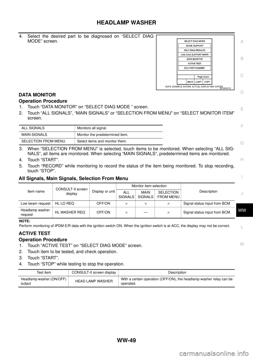
4. Select the desired part to be diagnosed on “SELECT DIAG
MODE” screen.
DATA MONITOR
Operation Procedure
1. Touch “DATA MONITOR” on “SELECT DIAG MODE ” screen.
2. Touch “ALL SIGNALS”, “MAIN SIGNALS” or “SELECTION FROM MENU” on “SELECT MONITOR ITEM”
screen.
3. When “SELECTION FROM MENU” is selected, touch items to be monitored. When selecting “ALL SIG-
NALS”, all items are monitored. When selecting “MAIN SIGNALS”, predetermined items are monitored.
4. Touch “START”.
5. Touch “RECORD” while monitoring to record the status of the item being monitored. To stop recording,
touch “STOP”.
All Signals, Main Signals, Selection From Menu
NOTE:
Perform monitoring of IPDM E/R data with the ignition switch ON. When the ignition switch is at ACC, the display may not be correct.
ACTIVE TEST
Operation Procedure
1. Touch “ACTIVE TEST” on “SELECT DIAG MODE” screen.
2. Touch item to be tested, and check operation.
3. Touch “START”.
4. Touch “STOP” while testing to stop the operation.
BCIA0031E
ALL SIGNALS Monitors all signal.
MAIN SIGNALS Monitor the predetermined item.
SELECTION FROM MENU Select items and monitor them.
Item nameCONSULT-II screen
displayDisplay or unitMonitor item selection
Description
ALL
SIGNALSMAIN
SIGNALSSELECTION
FROM MENU
Low beam request HL LO REQ OFF/ON´´ ´Signal status input from BCM
Headlamp washer
requestHL WASHER REQ OFF/ON´—´Signal status input from BCM
Test item CONSULT-II screen display Description
Headlamp washer (ON/OFF)
outputHEAD LAMP WASHERWith a certain operation (OFF/ON), the headlamp washer relay can be
operated.