2005 NISSAN NAVARA checking oil
[x] Cancel search: checking oilPage 214 of 3171
AT-206
TROUBLE DIAGNOSIS FOR SYMPTOMS
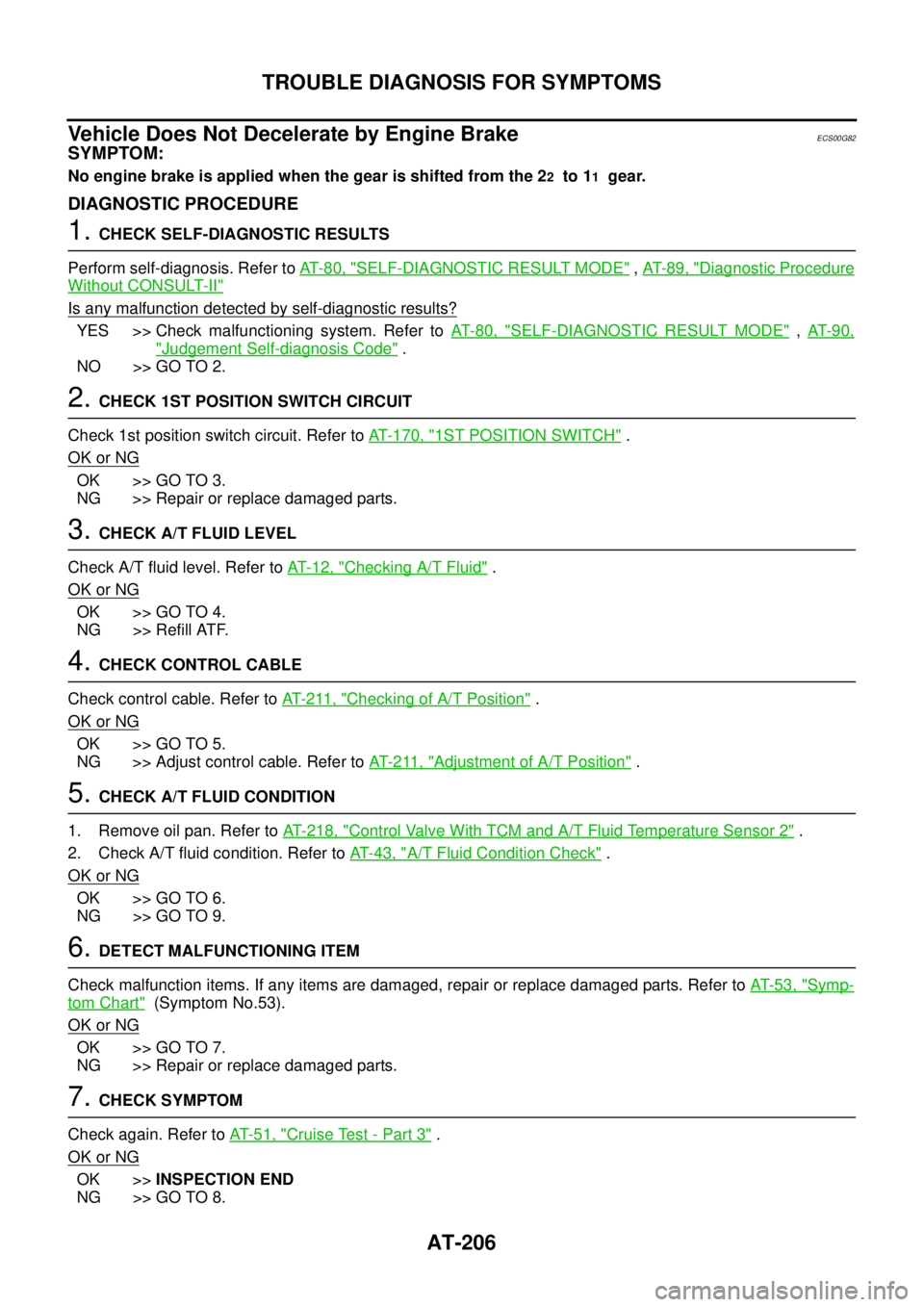
Vehicle Does Not Decelerate by Engine Brake
ECS00G82
SYMPTOM:
No engine brake is applied when the gear is shifted from the 22to 11gear.
DIAGNOSTIC PROCEDURE
1.CHECK SELF-DIAGNOSTIC RESULTS
Perform self-diagnosis. Refer toAT-80, "
SELF-DIAGNOSTIC RESULT MODE",AT-89, "Diagnostic Procedure
Without CONSULT-II"
Is any malfunction detected by self-diagnostic results?
YES >> Check malfunctioning system. Refer toAT-80, "SELF-DIAGNOSTIC RESULT MODE",AT- 9 0 ,
"Judgement Self-diagnosis Code".
NO >> GO TO 2.
2.CHECK 1ST POSITION SWITCH CIRCUIT
Check 1st position switch circuit. Refer toAT- 1 7 0 , "
1ST POSITION SWITCH".
OK or NG
OK >> GO TO 3.
NG >> Repair or replace damaged parts.
3.CHECK A/T FLUID LEVEL
Check A/T fluid level. Refer toAT-12, "
Checking A/T Fluid".
OK or NG
OK >> GO TO 4.
NG >> Refill ATF.
4.CHECK CONTROL CABLE
Check control cable. Refer toAT- 2 11 , "
Checking of A/T Position".
OK or NG
OK >> GO TO 5.
NG >> Adjust control cable. Refer toAT- 2 11 , "
Adjustment of A/T Position".
5.CHECK A/T FLUID CONDITION
1. Remove oil pan. Refer toAT- 2 1 8 , "
Control Valve With TCM and A/T Fluid Temperature Sensor 2".
2. Check A/T fluid condition. Refer toAT-43, "
A/T Fluid Condition Check".
OK or NG
OK >> GO TO 6.
NG >> GO TO 9.
6.DETECT MALFUNCTIONING ITEM
Check malfunction items. If any items are damaged, repair or replace damaged parts. Refer toAT-53, "
Symp-
tom Chart"(Symptom No.53).
OK or NG
OK >> GO TO 7.
NG >> Repair or replace damaged parts.
7.CHECK SYMPTOM
Check again. Refer toAT-51, "
Cruise Test - Part 3".
OK or NG
OK >>INSPECTION END
NG >> GO TO 8.
Page 242 of 3171
AT-234
ON-VEHICLE SERVICE
Installation
CAUTION:
After completing installation, check A/T fluid leakage, A/T fluid level and A/T position. Refer toAT- 1 2 ,
"Checking A/T Fluid",AT- 2 11 , "Checking of A/T Position".
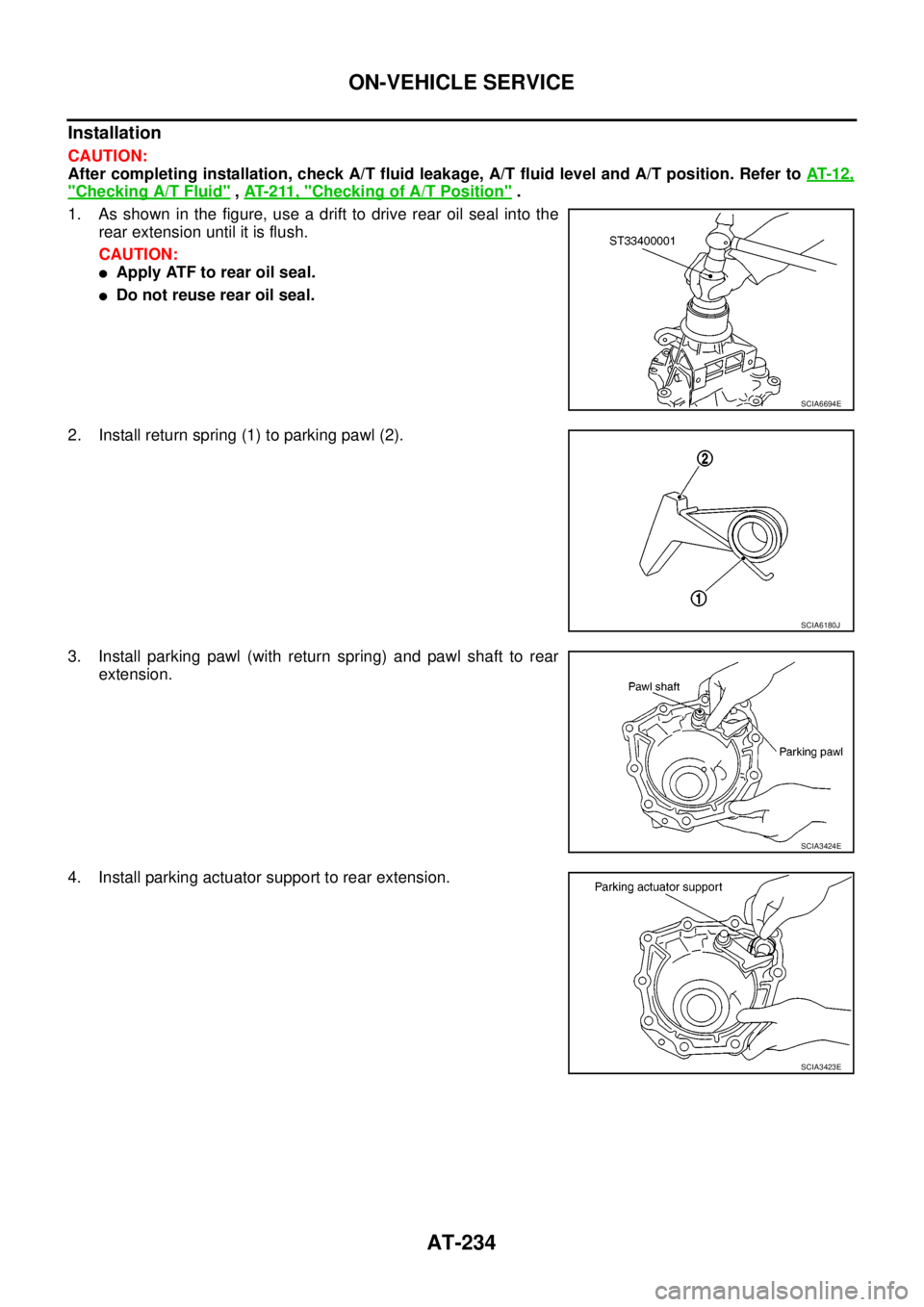
1. As shown in the figure, use a drift to drive rear oil seal into the
rear extension until it is flush.
CAUTION:
lApply ATF to rear oil seal.
lDo not reuse rear oil seal.
2. Install return spring (1) to parking pawl (2).
3. Install parking pawl (with return spring) and pawl shaft to rear
extension.
4. Install parking actuator support to rear extension.
SCIA6694E
SCIA6180J
SCIA3424E
SCIA3423E
Page 245 of 3171
ON-VEHICLE SERVICE
AT-237
D
E
F
G
H
I
J
K
L
MA
B
AT
Rear Oil SealECS00GVM
REMOVAL AND INSTALLATION
Removal
1. Remove rear propeller shaft. Refer toPR-8, "Removal and
Installation".
2. Remove transfer from A/T assembly (4WD models). Refer to
T F - 111 , "
Removal and Installation".
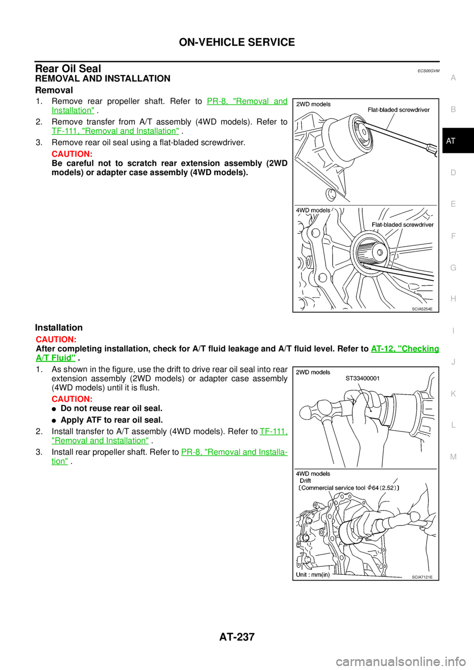
3. Remove rear oil seal using a flat-bladed screwdriver.
CAUTION:
Be careful not to scratch rear extension assembly (2WD
models) or adapter case assembly (4WD models).
Installation
CAUTION:
After completing installation, check for A/T fluid leakage and A/T fluid level. Refer toAT- 1 2 , "
Checking
A/T Fluid".
1. As shown in the figure, use the drift to drive rear oil seal into rear
extension assembly (2WD models) or adapter case assembly
(4WD models) until it is flush.
CAUTION:
lDo not reuse rear oil seal.
lApply ATF to rear oil seal.
2. Install transfer to A/T assembly (4WD models). Refer toT F - 111 ,
"Removal and Installation".
3. Install rear propeller shaft. Refer toPR-8, "
Removal and Installa-
tion".
SCIA5254E
SCIA7121E
Page 249 of 3171
ON-VEHICLE SERVICE
AT-241
D
E
F
G
H
I
J
K
L
MA
B
AT
Installation
CAUTION:
After completing installation, check A/T fluid leakage, A/T fluid level and A/T position. Refer toAT- 1 2 ,
"Checking A/T Fluid",AT- 2 11 , "Checking of A/T Position".
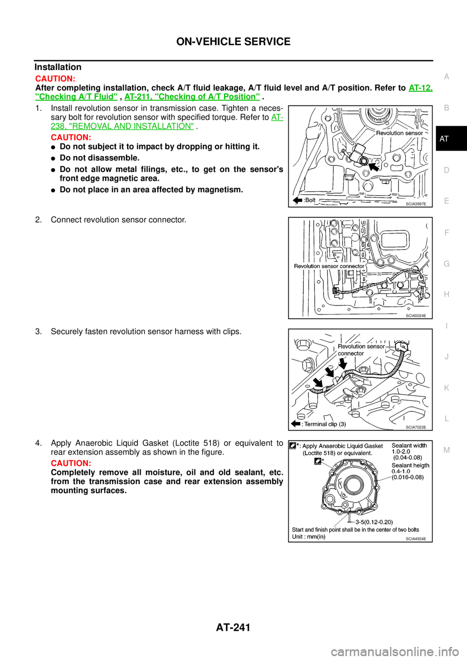
1. Install revolution sensor in transmission case. Tighten a neces-
sary bolt for revolution sensor with specified torque. Refer toAT-
238, "REMOVAL AND INSTALLATION".
CAUTION:
lDo not subject it to impact by dropping or hitting it.
lDo not disassemble.
lDo not allow metal filings, etc., to get on the sensor's
front edge magnetic area.
lDo not place in an area affected by magnetism.
2. Connect revolution sensor connector.
3. Securely fasten revolution sensor harness with clips.
4. Apply Anaerobic Liquid Gasket (Loctite 518) or equivalent to
rear extension assembly as shown in the figure.
CAUTION:
Completely remove all moisture, oil and old sealant, etc.
from the transmission case and rear extension assembly
mounting surfaces.
SCIA3997E
SCIA5024E
SCIA7022E
SCIA4934E
Page 460 of 3171
ATC-126
HEATER & COOLING UNIT ASSEMBLY
Removal and Installation
EJS006C9
REMOVAL
1. Discharge the refrigerant from the A/C system. Refer toATC-138, "Discharging Refrigerant".
2. Drain the coolant from the engine cooling system. Refer toCO-8, "
DRAINING ENGINE COOLANT".
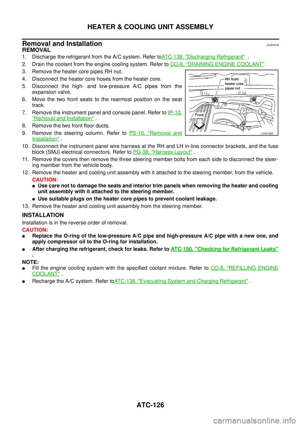
3. Remove the heater core pipes RH nut.
4. Disconnect the heater core hoses from the heater core.
5. Disconnect the high- and low-pressure A/C pipes from the
expansion valve.
6. Move the two front seats to the rearmost position on the seat
track.
7. Remove the instrument panel and console panel. Refer toIP-10,
"Removal and Installation".
8. Remove the two front floor ducts.
9. Remove the steering column. Refer toPS-10, "
Removal and
Installation".
10. Disconnect the instrument panel wire harness at the RH and LH in-line connector brackets, and the fuse
block (SMJ) electrical connectors. Refer toPG-38, "
Harness Layout".
11. Remove the covers then remove the three steering member bolts from each side to disconnect the steer-
ing member from the vehicle body.
12. Remove the heater and cooling unit assembly with it attached to the steering member, from the vehicle.
CAUTION:
lUse care not to damage the seats and interior trim panels when removing the heater and cooling
unit assembly with it attached to the steering member.
lUse suitable plugs on the heater core pipes to prevent coolant leakage.
13. Remove the heater and cooling unit assembly from the steering member.
INSTALLATION
Installation is in the reverse order of removal.
CAUTION:
lReplace the O-ring of the low-pressure A/C pipe and high-pressure A/C pipe with a new one, and
apply compressor oil to the O-ring for installation.
lAfter charging the refrigerant, check for leaks. Refer toATC-150, "Checking for Refrigerant Leaks"
.
NOTE:
lFill the engine cooling system with the specified coolant mixture. Refer toCO-8, "REFILLING ENGINE
COOLANT".
lRecharge the A/C system. Refer toATC-138, "Evacuating System and Charging Refrigerant".
LJIA0165E
Page 476 of 3171
ATC-142
REFRIGERANT LINES
Removal and Installation for Compressor
EJS006CN
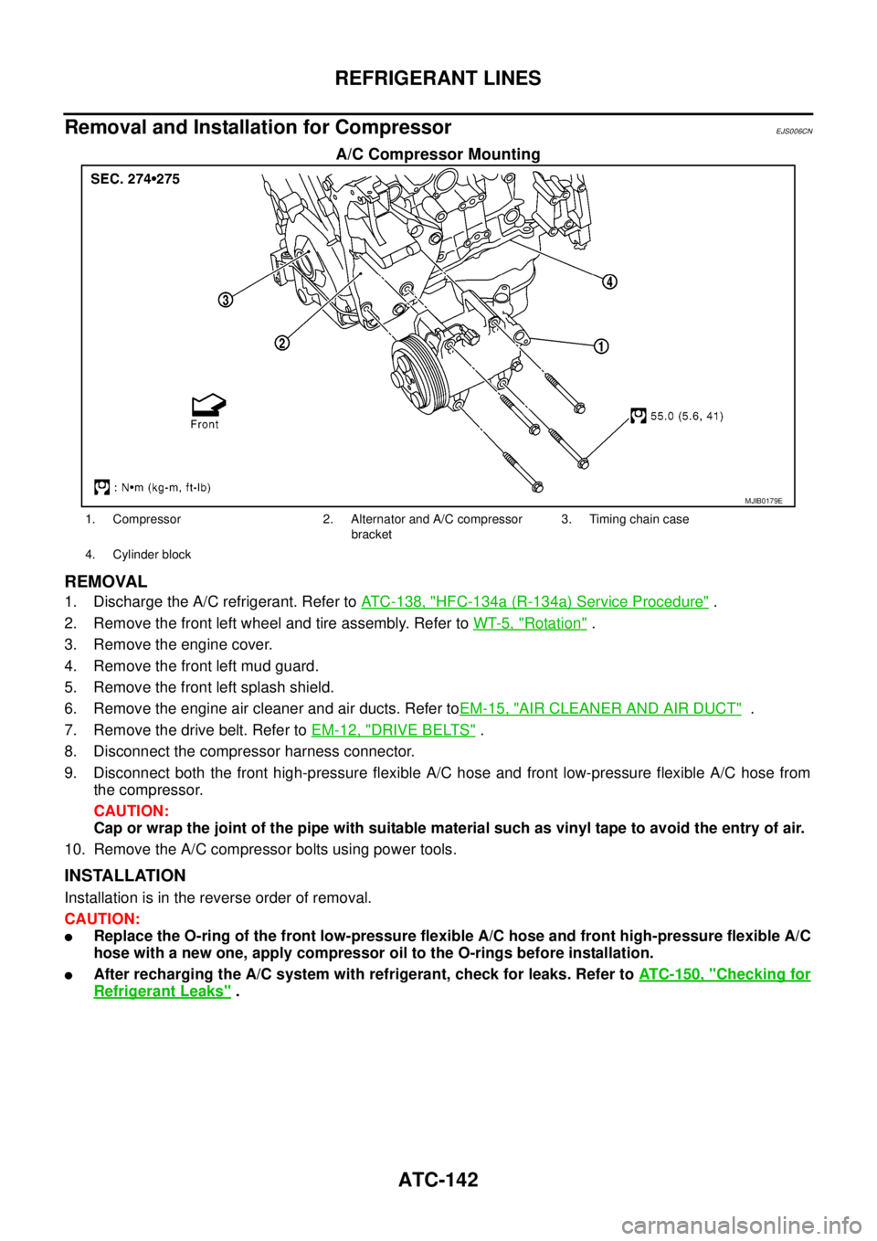
A/C Compressor Mounting
REMOVAL
1. Discharge the A/C refrigerant. Refer toATC-138, "HFC-134a (R-134a) Service Procedure".
2. Remove the front left wheel and tire assembly. Refer toWT-5, "
Rotation".
3. Remove the engine cover.
4. Remove the front left mud guard.
5. Remove the front left splash shield.
6. Remove the engine air cleaner and air ducts. Refer toEM-15, "
AIR CLEANER AND AIR DUCT".
7. Remove the drive belt. Refer toEM-12, "
DRIVE BELTS".
8. Disconnect the compressor harness connector.
9. Disconnect both the front high-pressure flexible A/C hose and front low-pressure flexible A/C hose from
the compressor.
CAUTION:
Cap or wrap the joint of the pipe with suitable material such as vinyl tape to avoid the entry of air.
10. Remove the A/C compressor bolts using power tools.
INSTALLATION
Installation is in the reverse order of removal.
CAUTION:
lReplace the O-ring of the front low-pressure flexible A/C hose and front high-pressure flexible A/C
hose with a new one, apply compressor oil to the O-rings before installation.
lAfter recharging the A/C system with refrigerant, check for leaks. Refer toATC-150, "Checking for
Refrigerant Leaks".
MJIB0179E
1. Compressor 2. Alternator and A/C compressor
bracket3. Timing chain case
4. Cylinder block
Page 484 of 3171
ATC-150
REFRIGERANT LINES
CAUTION:
Replace the O-rings on the A/C low-pressure flexible A/C hose and the high-pressure A/C pipe with
new ones. Apply compressor oil to the O-rings for installation.
Removal and Installation for Expansion ValveEJS006CZ
REMOVAL
1. Discharge the refrigerant. Refer toATC-138, "HFC-134a (R-134a) Service Procedure".
2. Remove the heater and cooling unit assembly. Refer toATC-126, "
REMOVAL".
3. Remove the heater core and evaporator pipes grommet.
4. Remove the expansion valve.
INSTALLATION
Installation is in the reverse order of removal.
CAUTION:
lReplace the O-rings on then expansion valve and the A/C refrigerant pipes with new ones, then
apply compressor oil to them for installation.
lAfter charging refrigerant, check for leaks.
Checking for Refrigerant LeaksEJS006D1
Perform a visual inspection of all refrigeration parts, fittings, hoses and components for signs of A/C lubricant
leakage, damage and corrosion. A/C lubricant leakage may indicate an area of refrigerant leakage. Allow
extra inspection time in these areas when using either an electronic refrigerant leak detector or fluorescent
dye leak detector.
If dye is observed, confirm the leak with an electronic refrigerant leak detector. It is possible a prior leak was
repaired and not properly cleaned.
When searching for leaks, do not stop when one leak is found but continue to check for additional leaks at all
system components and connections.
When searching for refrigerant leaks using an electronic leak detector, move the probe along the suspected
leak area at 1 to 2 inches per second and no further than 1/4 inch from the component.
CAUTION:
Moving the electronic leak detector probe slower and closer to the suspected leak area will improve
the chances of finding a leak.
Checking System for Leaks Using the Fluorescent Leak DetectorEJS006D2
1. Check A/C system for leaks using the UV lamp and safety goggles [SST: J-42220] in a low sunlight area
(area without windows preferable). Illuminate all components, fittings and lines. The dye will appear as a
bright green/yellow area at the point of leakage. Fluorescent dye observed at the evaporator drain open-
ing indicates an evaporator core assembly (tubes, core or expansion valve) leak.
2. If the suspected area is difficult to see, use an adjustable mirror or wipe the area with a clean shop rag or
cloth, with the UV lamp for dye residue.
3. After the leak is repaired, remove any residual dye using dye cleaner [SST: J-43872] to prevent future mis-
diagnosis.
4. Perform a system performance check and verify the leak repair with an approved electronic refrigerant
leak detector.
NOTE:
Other gases in the work area or substances on the A/C components, for example, anti-freeze, windshield
washer fluid, solvents and lubricants, may falsely trigger the leak detector. Make sure the surfaces to be
checked are clean.
Cleanwithadryclothorblowoffwithshopair.
Do not allow the sensor tip of the detector to contact with any substance. This can also cause false readings
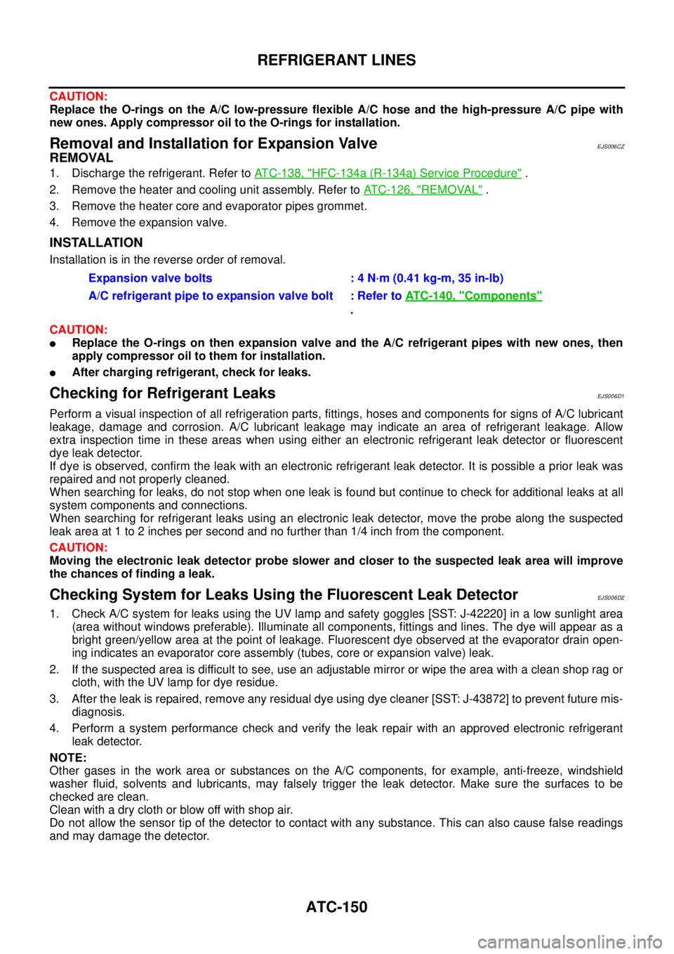
and may damage the detector.Expansion valve bolts : 4 N·m (0.41 kg-m, 35 in-lb)
A/C refrigerant pipe to expansion valve bolt : Refer toATC-140, "
Components"
.
Page 897 of 3171
RADIATOR
CO-13
C
D
E
F
G
H
I
J
K
L
MA
CO
INSPECTION AFTER REMOVAL
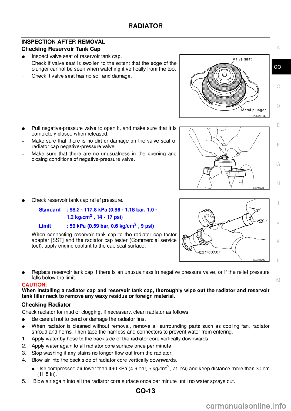
Checking Reservoir Tank Cap
lInspect valve seat of reservoir tank cap.
–Check if valve seat is swollen to the extent that the edge of the
plunger cannot be seen when watching it vertically from the top.
–Check if valve seat has no soil and damage.
lPull negative-pressure valve to open it, and make sure that it is
completely closed when released.
–Make sure that there is no dirt or damage on the valve seat of
radiator cap negative-pressure valve.
–Make sure that there are no unusualness in the opening and
closing conditions of negative-pressure valve.
lCheck reservoir tank cap relief pressure.
–When connecting reservoir tank cap to the radiator cap tester
adapter [SST] and the radiator cap tester (Commercial service
tool), apply engine coolant to the cap seal surface.
lReplace reservoir tank cap if there is an unusualness in negative pressure valve, or if the relief pressure
falls below the limit.
CAUTION:
When installing a radiator cap and reservoir tank cap, thoroughly wipe out the radiator and reservoir
tank filler neck to remove any waxy residue or foreign material.
Checking Radiator
Check radiator for mud or clogging. If necessary, clean radiator as follows.
lBe careful not to bend or damage the radiator fins.
lWhen radiator is cleaned without removal, remove all surrounding parts such as cooling fan, radiator
shroud and horns. Then tape the harness and connectors to prevent water from entering.
1. Apply water by hose to the back side of the radiator core vertically downwards.
2. Apply water again to all radiator core surface once per minute.
3. Stop washing if any stains no longer flow out from the radiator.
4. Blow air into the back side of radiator core vertically downwards.
lUse compressed air lower than 490 kPa (4.9 bar, 5 kg/cm2, 71 psi) and keep distance more than 30 cm
(11.8 in).
5. Blow air again into all the radiator core surface once per minute until no water sprays out.
PBIC2816E
SMA967B
Standard : 98.2 - 117.8 kPa (0.98 - 1.18 bar, 1.0 -
1.2 kg/cm
2,14-17psi)
Limit : 59 kPa (0.59 bar, 0.6 kg/cm
2,9psi)
SLC755AC