2005 NISSAN NAVARA checking oil
[x] Cancel search: checking oilPage 908 of 3171
CO-24
THERMOSTAT AND WATER PIPING
Removal and Installation
EBS01E6X
WARNING:
Do not remove radiator cap and/or reservoir tank cap when engine is hot. Serious burns could occur
from high pressure engine coolant escaping from radiator and/or reservoir tank.
REMOVAL
1. Remove front engine undercover and middle engine undercover. Refer toEI-15, "FRONT BUMPER".
2. Drain engine coolant from radiator drain plug at the bottom of radiator, and from water drain plug at the
side of cylinder block. Refer toCO-7, "
Changing Engine Coolant"andEM-110, "CYLINDER BLOCK".
CAUTION:
Perform this step when engine is cold.
3. Remove engine cover. Refer toEM-20, "
INTAKE MANIFOLD".
4. Disconnect radiator hoses (upper and lower) from engine side. Refer toCO-11, "
RADIATOR".
5. Remove air inlet pipe and air duct between air cleaner case and turbocharger. Refer toEM-15, "
AIR
CLEANER AND AIR DUCT"andEM-28, "TURBO CHARGER".
6. Remove water outlet, water inlet and thermostat.
7. Remove thermostat housing.
8. Disconnect heater return hose and water hoses at heater return pipe side, and remove heater return pipe.
9. Remove oil level gauge guide mounting bolt, vacuum hoses (to turbocharger boost control solenoid valve)
and spill hose. Refer toEM-36, "
OIL PAN AND OIL STRAINER",EM-20, "INTAKE MANIFOLD"andEM-
44, "INJECTION TUBE AND FUEL INJECTOR".
10. Disconnect water hoses (to EGR cooler) (A/T models), vacuum hoses and heater feed hose at heater
feed pipe side, and remove heater feed pipe. Refer toEM-20, "
INTAKE MANIFOLD".
INSPECTION AFTER REMOVAL
Thermostat
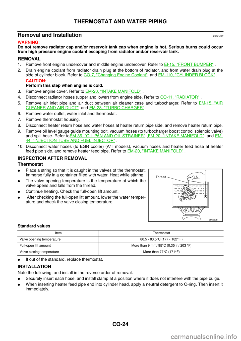
lPlace a string so that it is caught in the valves of the thermostat.
Immerse fully in a container filled with water. Heat while stirring.
lThe valve opening temperature is the temperature at which the
valve opens and falls from the thread.
lContinue heating. Check the full-open lift amount.
lAfter checking the full-open lift amount, lower the water temper-
ature and check the valve closing temperature.
Standard values
lIf out of the standard, replace thermostat.
INSTALLATION
Note the following, and install in the reverse order of removal.
lSecurely insert each hose, and install clamp at a position where it does not interfere with the pipe bulge.
lWhen inserting heater feed pipe end into cylinder head, apply a neutral detergent to O-ring. Then insert it
immediately.
SLC252B
Item Thermostat
Valve opening temperature 80.5 - 83.5°C (177 - 182°F)
Full-open lift amount More than 9 mm/ 95°C (0.35 in/ 203°F)
Valve closing temperature More than 77°C(171°F)
Page 1383 of 3171
EM-1
ENGINE MECHANICAL
B ENGINE
CONTENTS
C
D
E
F
G
H
I
J
K
L
M
SECTIONEM
A
EM
ENGINE MECHANICAL
PRECAUTIONS .......................................................... 4
Precautions for Draining Engine Coolant ................. 4
Precautions for Disconnecting Fuel Piping .............. 4
Precautions for Removal and Disassembly ............. 4
Precautions for Inspection, Repair and Replace-
ment ......................................................................... 4
Precautions for Assembly and Installation ............... 4
Parts Requiring Angle Tightening ............................. 4
Precautions For Liquid Gasket ................................. 5
REMOVAL OF LIQUID GASKET .......................... 5
LIQUID GASKET APPLICATION PROCEDURE..... 5
PREPARATION ........................................................... 6
Special Service Tools ............................................... 6
Commercial Service Tools ........................................ 8
NOISE, VIBRATION AND HARSHNESS (NVH)
TROUBLESHOOTING .............................................. 10
NVH Troubleshooting — Engine Noise .................. 10
Use the Chart Below to Help You Find the Cause
of the Symptom. ...................................................... 11
DRIVE BELTS ........................................................... 12
Checking Drive Belts .............................................. 12
Deflection Adjustment ............................................ 13
POWER STEERING OIL PUMP BELT ............... 13
A/C COMPRESSOR, ALTERNATOR AND
WATER PUMP BELT .......................................... 14
Removal and Installation ........................................ 14
REMOVAL ........................................................... 14
INSTALLATION ................................................... 14
AIR CLEANER AND AIR DUCT ............................... 15
Components ........................................................... 15
Removal and Installation ........................................ 15
REMOVAL ........................................................... 15
INSTALLATION ................................................... 16
CHANGING AIR CLEANER FILTER ................... 17
CHARGE AIR COOLER ........................................... 18
Components ........................................................... 18
Removal and Installation ........................................ 18
REMOVAL ........................................................... 18
INSPECTION AFTER REMOVAL ....................... 19
INSTALLATION ................................................... 19INTAKE MANIFOLD ................................................. 20
Components ........................................................... 20
Removal and Installation ........................................ 21
REMOVAL ........................................................... 21
INSPECTION AFTER REMOVAL ....................... 22
INSTALLATION ................................................... 22
INSPECTION AFTER INSTALLATION ................ 25
CATALYST ................................................................ 26
Components ........................................................... 26
Removal and Installation ........................................ 26
REMOVAL ........................................................... 26
INSTALLATION ................................................... 27
TURBO CHARGER ................................................... 28
Components ........................................................... 28
Removal and Installation ........................................ 29
REMOVAL ........................................................... 29
INSPECTION AFTER REMOVAL ....................... 30
TROUBLE DIAGNOSIS OF TURBOCHARGER... 32
INSTALLATION ................................................... 33
EXHAUST MANIFOLD ............................................. 34
Components ........................................................... 34
Removal and Installation ........................................ 34
REMOVAL ........................................................... 34
INSPECTION AFTER REMOVAL ....................... 35
INSTALLATION ................................................... 35
INSPECTION AFTER INSTALLATION ................ 35
OIL PAN AND OIL STRAINER ................................. 36
Components ........................................................... 36
Removal and Installation ........................................ 36
REMOVAL ........................................................... 36
INSPECTION AFTER REMOVAL ....................... 38
INSTALLATION ................................................... 38
INSPECTION AFTER INSTALLATION ................ 40
GLOW PLUG ............................................................ 41
Components ........................................................... 41
Removal and Installation ........................................ 41
REMOVAL ........................................................... 41
INSTALLATION ................................................... 41
VACUUM PUMP ........................................................ 42
Page 1384 of 3171
EM-2
Components ........................................................... 42
Removal and Installation ........................................ 42
INSPECTION BEFORE REMOVAL ..................... 42
REMOVAL ........................................................... 42
INSTALLATION .................................................... 43
INJECTION TUBE AND FUEL INJECTOR .............. 44
Components ........................................................... 44
Removal and Installation ........................................ 44
REMOVAL ........................................................... 44
INSTALLATION .................................................... 46
INSPECTION AFTER INSTALLATION ................ 48
FUEL PUMP .............................................................. 49
Components ........................................................... 49
Removal and Installation ........................................ 49
REMOVAL ........................................................... 49
INSPECTION AFTER REMOVAL ........................ 52
INSTALLATION .................................................... 52
ROCKER COVER ..................................................... 56
Components ........................................................... 56
Removal and Installation ........................................ 56
REMOVAL ........................................................... 56
INSTALLATION .................................................... 57
INSPECTION AFTER INSTALLATION ................ 58
CAMSHAFT ............................................................... 59
Components ........................................................... 59
Removal and Installation ........................................ 59
REMOVAL ........................................................... 59
INSPECTION AFTER REMOVAL ........................ 60
INSTALLATION .................................................... 63
INSPECTION AFTER INSTALLATION ................ 65
Valve Clearance ...................................................... 66
INSPECTION ....................................................... 66
ADJUSTMENTS .................................................. 67
OIL SEAL .................................................................. 70
Removal and Installation of Valve Oil Seal ............. 70
REMOVAL ........................................................... 70
INSTALLATION .................................................... 70
Removal and Installation of Front Oil Seal ............. 71
REMOVAL ........................................................... 71
INSTALLATION .................................................... 71
Removal and Installation of Rear Oil Seal .............. 72
REMOVAL ........................................................... 72
INSTALLATION .................................................... 72
SECONDARY TIMING CHAIN .................................. 73
Components ........................................................... 73
Removal and Installation ........................................ 73
REMOVAL ........................................................... 73
INSPECTION AFTER REMOVAL ........................ 75
INSTALLATION .................................................... 75
INSPECTION AFTER INSTALLATION ................ 77
PRIMARY TIMING CHAIN ........................................ 79
Components ........................................................... 79
Removal and Installation ........................................ 80
REMOVAL ........................................................... 80
INSPECTION AFTER REMOVAL ........................ 84
INSTALLATION .................................................... 85
INSPECTION AFTER INSTALLATION ................ 91CYLINDER HEAD ..................................................... 92
On-Vehicle Service ................................................. 92
CHECKING COMPRESSION PRESSURE ......... 92
Components ............................................................ 93
Removal and Installation ......................................... 94
REMOVAL ............................................................ 94
INSPECTION AFTER REMOVAL ........................ 94
INSTALLATION .................................................... 96
INSPECTION AFTER INSTALLATION ................ 98
Components ............................................................ 99
Disassembly and Assembly .................................... 99
DISASSEMBLY .................................................... 99
ASSEMBLY ........................................................100
INSPECTION AFTER DISASSEMBLY ..............101
ENGINE ASSEMBLY ...............................................106
Components ..........................................................106
Removal and Installation .......................................106
REMOVAL ..........................................................107
INSTALLATION ..................................................108
INSPECTION AFTER INSTALLATION ..............108
CYLINDER BLOCK .................................................110
Components ..........................................................110
Disassembly and Assembly .................................. 111
DISASSEMBLY .................................................. 111
ASSEMBLY ........................................................114
How to Select Piston and Bearing ........................121
DESCRIPTION ..................................................121
HOW TO SELECT PISTON ...............................121
HOW TO SELECT CONNECTING ROD BEAR-
ING .....................................................................122
HOW TO SELECT MAIN BEARING ..................123
Inspection After Disassembly ................................124
CRANKSHAFT END PLAY ................................124
CONNECTING ROD SIDE CLEARANCE .........125
PISTON TO PISTON PIN CLEARANCE ...........125
PISTON RING SIDE CLEARANCE ...................126
PISTON RING END GAP ..................................126
CONNECTING ROD BEND AND TORSION .....127
CONNECTING ROD BIG END INNER DIAME-
TER ....................................................................127
CONNECTING ROD BUSHING OIL CLEAR-
ANCE .................................................................127
CYLINDER BLOCK TOP SURFACE DISTOR-
TION ..................................................................128
MAIN BEARING HOUSING INNER DIAMETER.128
PISTON TO CYLINDER BORE CLEARANCE ..129
CRANKSHAFT MAIN JOURNAL DIAMETER ...130
CRANKSHAFT PIN JOURNAL DIAMETER ......130
CRANKSHAFT OUT-OF-ROUND AND TAPER.130
CRANKSHAFT RUNOUT ..................................131
CONNECTING ROD BEARING OIL CLEAR-
ANCE .................................................................131
MAIN BEARING OIL CLEARANCE ...................132
CRUSH HEIGHT OF MAIN BEARING ..............132
CRUSH HEIGHT OF CONNECTING ROD
Page 1388 of 3171
EM-6
PREPARATION
PREPARATION
PFP:00002
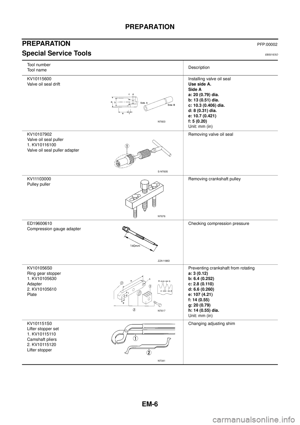
Special Service ToolsEBS01E5O
Tool number
Tool nameDescription
KV10115600
Valve oil seal driftInstalling valve oil seal
UsesideA.
Side A
a: 20 (0.79) dia.
b: 13 (0.51) dia.
c: 10.3 (0.406) dia.
d: 8 (0.31) dia.
e: 10.7 (0.421)
f: 5 (0.20)
Unit: mm (in)
KV10107902
Valve oil seal puller
1. KV10116100
Valve oil seal puller adapterRemoving valve oil seal
KV11103000
Pulley pullerRemoving crankshaft pulley
ED19600610
Compression gauge adapterChecking compression pressure
KV101056S0
Ring gear stopper
1. KV10105630
Adapter
2. KV10105610
PlatePreventing crankshaft from rotating
a: 3 (0.12)
b: 6.4 (0.252)
c: 2.8 (0.110)
d: 6.6 (0.260)
e: 107 (4.21)
f: 14 (0.55)
g: 20 (0.79)
h: 14 (0.55) dia.
Unit: mm (in)
KV101151S0
Lifter stopper set
1. KV10115110
Camshaft pliers
2. KV10115120
Lifter stopperChanging adjusting shim
NT603
S-NT605
NT676
ZZA1188D
NT617
NT041
Page 1394 of 3171
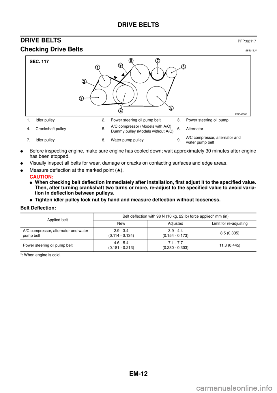
EM-12
DRIVE BELTS
DRIVE BELTS
PFP:02117
Checking Drive BeltsEBS01EJ4
lBefore inspecting engine, make sure engine has cooled down; wait approximately 30 minutes after engine
has been stopped.
lVisually inspect all belts for wear, damage or cracks on contacting surfaces and edge areas.
lMeasure deflection at the marked point ( ).
CAUTION:
lWhen checking belt deflection immediately after installation, first adjust it to the specified value.
Then, after turning crankshaft two turns or more, re-adjust to the specified value to avoid varia-
tion in deflection between pulleys.
lTighten idler pulley lock nut by hand and measure deflection without looseness.
Belt Deflection:
*: When engine is cold.1. Idler pulley 2. Power steering oil pump belt 3. Power steering oil pump
4. Crankshaft pulley 5.A/C compressor (Models with A/C)
Dummypulley(ModelswithoutA/C)6. Alternator
7. Idler pulley 8. Water pump pulley 9.A/C compressor, alternator and
water pump belt
PBIC4038E
Applied beltBelt deflection with 98 N (10 kg, 22 lb) force applied* mm (in)
New Adjusted Limit for re-adjusting
A/C compressor, alternator and water
pump belt2.9 - 3.4
(0.114 - 0.134)3.9 - 4.4
(0.154 - 0.173)8.5 (0.335)
Power steering oil pump belt4.6 - 5.4
(0.181 - 0.213)7.1 - 7.7
(0.280 - 0.303)11.3 (0.445)
Page 1395 of 3171
DRIVE BELTS
EM-13
C
D
E
F
G
H
I
J
K
L
MA
EM
Deflection AdjustmentEBS01EJ5
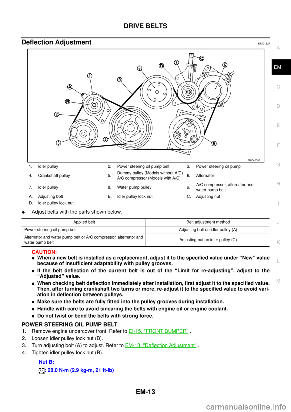
lAdjust belts with the parts shown below.
CAUTION:
lWhen a new belt is installed as a replacement, adjust it to the specified value under “New” value
because of insufficient adaptability with pulley grooves.
lIf the belt deflection of the current belt is out of the “Limit for re-adjusting”, adjust to the
“Adjusted” value.
lWhen checking belt deflection immediately after installation, first adjust it to the specified value.
Then, after turning crankshaft two turns or more, re-adjust it to the specified value to avoid vari-
ation in deflection between pulleys.
lMake sure the belts are fully fitted into the pulley grooves during installation.
lHandle with care to avoid smearing the belts with engine oil or engine coolant.
lDo not twist or bend the belts with strong force.
POWER STEERING OIL PUMP BELT
1. Remove engine undercover front. Refer toEI-15, "FRONT BUMPER".
2. Loosen idler pulley lock nut (B).
3. Turn adjusting bolt (A) to adjust. Refer toEM-13, "
Deflection Adjustment".
4. Tighten idler pulley lock nut (B).
1. Idler pulley 2. Power steering oil pump belt 3. Power steering oil pump
4. Crankshaft pulley 5.Dummy pulley (Models without A/C)
A/C compressor (Models with A/C)6. Alternator
7. Idler pulley 8. Water pump pulley 9.A/C compressor, alternator and
water pump belt
A. Adjusting bolt B. Idler pulley lock nut C. Adjusting nut
D. Idler pulley lock nut
PBIC4039E
Applied belt Belt adjustment method
Power steering oil pump belt Adjusting bolt on idler pulley (A)
Alternator and water pump belt or A/C compressor, alternator and
water pump beltAdjusting nut on idler pulley (C)
Nut B:
: 28.0 N·m (2.9 kg-m, 21 ft-lb)
Page 1414 of 3171
EM-32
TURBO CHARGER
Turbocharger Boost Control Actuator
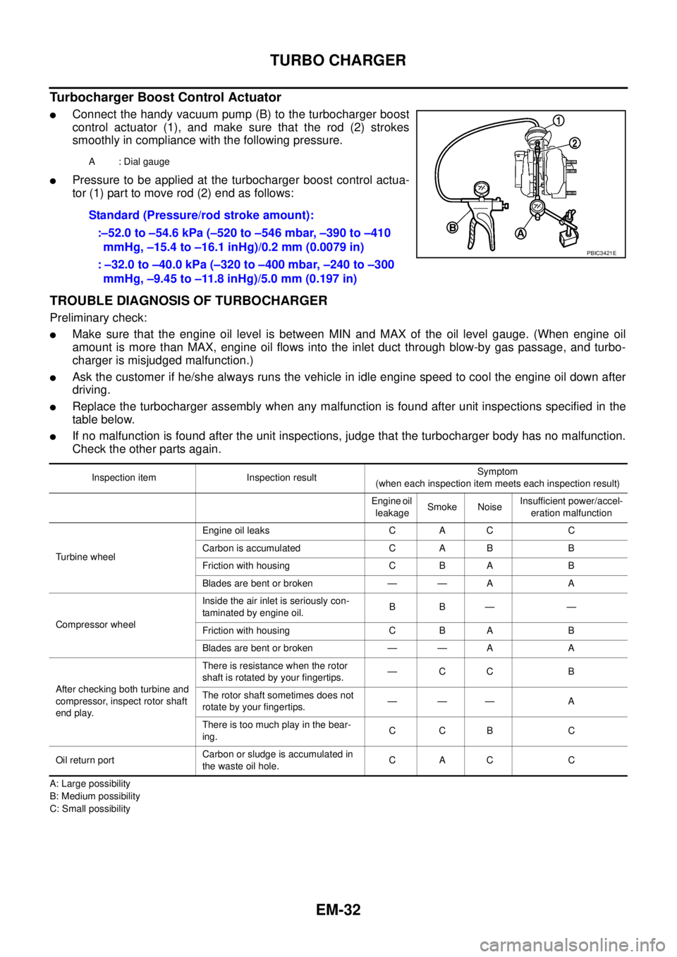
lConnect the handy vacuum pump (B) to the turbocharger boost
control actuator (1), and make sure that the rod (2) strokes
smoothly in compliance with the following pressure.
lPressure to be applied at the turbocharger boost control actua-
tor (1) part to move rod (2) end as follows:
TROUBLE DIAGNOSIS OF TURBOCHARGER
Preliminary check:
lMake sure that the engine oil level is between MIN and MAX of the oil level gauge. (When engine oil
amount is more than MAX, engine oil flows into the inlet duct through blow-by gas passage, and turbo-
charger is misjudged malfunction.)
lAsk the customer if he/she always runs the vehicle in idle engine speed to cool the engine oil down after
driving.
lReplace the turbocharger assembly when any malfunction is found after unit inspections specified in the
table below.
lIf no malfunction is found after the unit inspections, judge that the turbocharger body has no malfunction.
Check the other parts again.
A: Large possibility
B: Medium possibility
C: Small possibilityA : Dial gauge
Standard (Pressure/rod stroke amount):
:–52.0 to –54.6 kPa (–520 to –546 mbar, –390 to –410
mmHg, –15.4 to –16.1 inHg)/0.2 mm (0.0079 in)
: –32.0 to –40.0 kPa (–320 to –400 mbar, –240 to –300
mmHg, –9.45 to –11.8 inHg)/5.0 mm (0.197 in)
PBIC3421E
Inspection item Inspection resultSymptom
(when each inspection item meets each inspection result)
Engine oil
leakageSmoke NoiseInsufficient power/accel-
eration malfunction
Turbine wheelEngine oil leaks C A C C
Carbon is accumulated C A B B
Friction with housing C B A B
Blades are bent or broken — — A A
Compressor wheelInside the air inlet is seriously con-
taminated by engine oil.BB— —
Friction with housing C B A B
Blades are bent or broken — — A A
After checking both turbine and
compressor, inspect rotor shaft
end play.There is resistance when the rotor
shaft is rotated by your fingertips.—CC B
The rotor shaft sometimes does not
rotate by your fingertips.——— A
There is too much play in the bear-
ing.CCB C
Oil return portCarbon or sludge is accumulated in
the waste oil hole.CAC C
Page 1447 of 3171
CAMSHAFT
EM-65
C
D
E
F
G
H
I
J
K
L
MA
EM
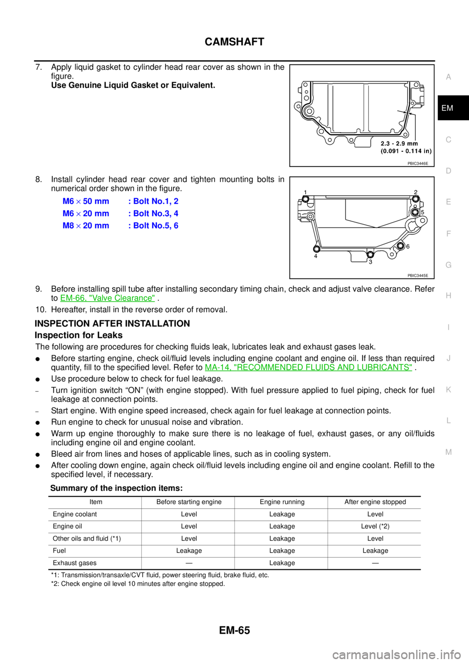
7. Apply liquid gasket to cylinder head rear cover as shown in the
figure.
Use Genuine Liquid Gasket or Equivalent.
8. Install cylinder head rear cover and tighten mounting bolts in
numerical order shown in the figure.
9. Before installing spill tube after installing secondary timing chain, check and adjust valve clearance. Refer
toEM-66, "
Valve Clearance".
10. Hereafter, install in the reverse order of removal.
INSPECTION AFTER INSTALLATION
Inspection for Leaks
The following are procedures for checking fluids leak, lubricates leak and exhaust gases leak.
lBefore starting engine, check oil/fluid levels including engine coolant and engine oil. If less than required
quantity, fill to the specified level. Refer toMA-14, "
RECOMMENDED FLUIDS AND LUBRICANTS".
lUse procedure below to check for fuel leakage.
–Turn ignition switch “ON” (with engine stopped). With fuel pressure applied to fuel piping, check for fuel
leakage at connection points.
–Start engine. With engine speed increased, check again for fuel leakage at connection points.
lRun engine to check for unusual noise and vibration.
lWarm up engine thoroughly to make sure there is no leakage of fuel, exhaust gases, or any oil/fluids
including engine oil and engine coolant.
lBleed air from lines and hoses of applicable lines, such as in cooling system.
lAfter cooling down engine, again check oil/fluid levels including engine oil and engine coolant. Refill to the
specified level, if necessary.
Summary of the inspection items:
*1: Transmission/transaxle/CVT fluid, power steering fluid, brake fluid, etc.
*2: Check engine oil level 10 minutes after engine stopped.
PBIC3446E
M6´50 mm : Bolt No.1, 2
M6´20 mm : Bolt No.3, 4
M8´20 mm : Bolt No.5, 6
PBIC3445E
Item Before starting engine Engine running After engine stopped
Engine coolant Level Leakage Level
Engine oil Level Leakage Level (*2)
Other oils and fluid (*1) Level Leakage Level
Fuel Leakage Leakage Leakage
Exhaust gases — Leakage —