2005 NISSAN NAVARA automatic transmission
[x] Cancel search: automatic transmissionPage 1645 of 3171

HOW TO USE THIS MANUAL
GI-23
C
D
E
F
G
H
I
J
K
L
MB
GI
AbbreviationsEAS001GZ
The followingABBREVIATIONSare used:
ABBREVIATION DESCRIPTION
A/C Air Conditioner
A/T Automatic Transaxle/Transmission
ATF Automatic Transmission Fluid
D
1Drive range 1st gear
D
2Drive range 2nd gear
D
3Drive range 3rd gear
D
4Drive range 4th gear
FR, RR Front, Rear
LH, RH Left-Hand, Right-Hand
M/T Manual Transaxle/Transmission
OD Overdrive
P/S Power Steering
SAE Society of Automotive Engineers, Inc.
SDS Service Data and Specifications
SST Special Service Tools
2WD 2-Wheel Drive
2
22nd range 2nd gear
2
12nd range 1st gear
1
21st range 2nd gear
1
11st range 1st gear
Page 1675 of 3171
TOW TRUCK TOWING
GI-53
C
D
E
F
G
H
I
J
K
L
MB
GI
TOW TRUCK TOWINGPFP:00000
To w Tr u c k To w i n gEAS001DI
WARNING:
lNever get under the vehicle while it is supported only by the jack. Always use safety stands to
support the frame when you have to get under the vehicle.
lPlace wheel chocks at both front and back of the wheels on the ground.
CAUTION:
lAll applicable local laws regarding the towing operation must be obeyed.
lIt is necessary to use proper towing equipment to avoid possible damage during towing opera-
tion. Towing is in accordance with Towing Procedure Manual at dealer.
lAlways attach safety chains before towing.
lWhen towing, make sure that the transmission, steering system and powertrain are in good order.
If any unit is damaged, dollies must be used.
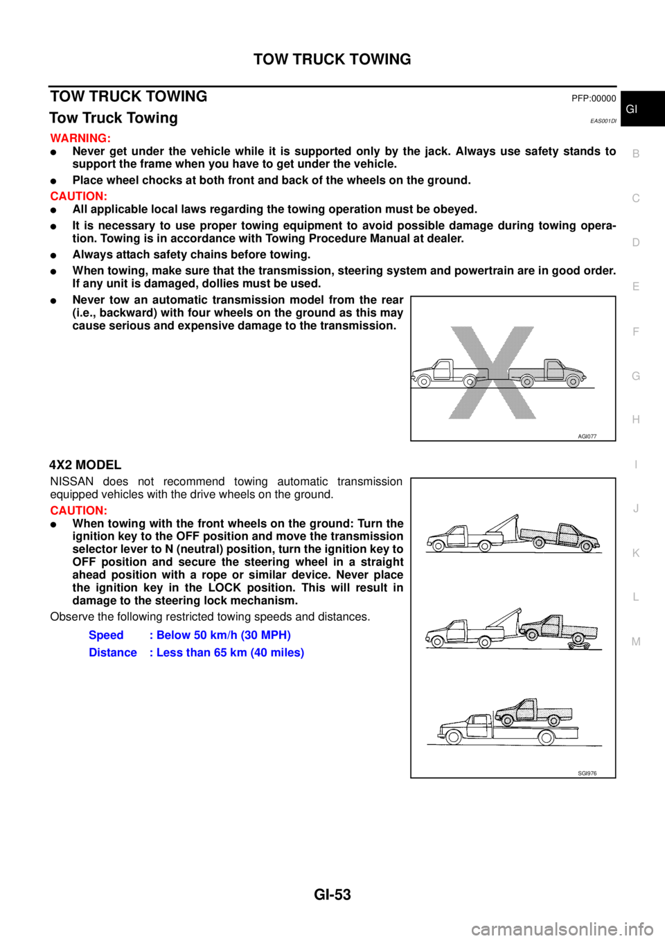
lNever tow an automatic transmission model from the rear
(i.e., backward) with four wheels on the ground as this may
cause serious and expensive damage to the transmission.
4X2 MODEL
NISSAN does not recommend towing automatic transmission
equipped vehicles with the drive wheels on the ground.
CAUTION:
lWhen towing with the front wheels on the ground: Turn the
ignition key to the OFF position and move the transmission
selector lever to N (neutral) position, turn the ignition key to
OFF position and secure the steering wheel in a straight
ahead position with a rope or similar device. Never place
the ignition key in the LOCK position. This will result in
damage to the steering lock mechanism.
Observe the following restricted towing speeds and distances.
AGI077
Speed : Below 50 km/h (30 MPH)
Distance : Less than 65 km (40 miles)
SGI976
Page 1676 of 3171
GI-54
TOW TRUCK TOWING
4X4 MODEL
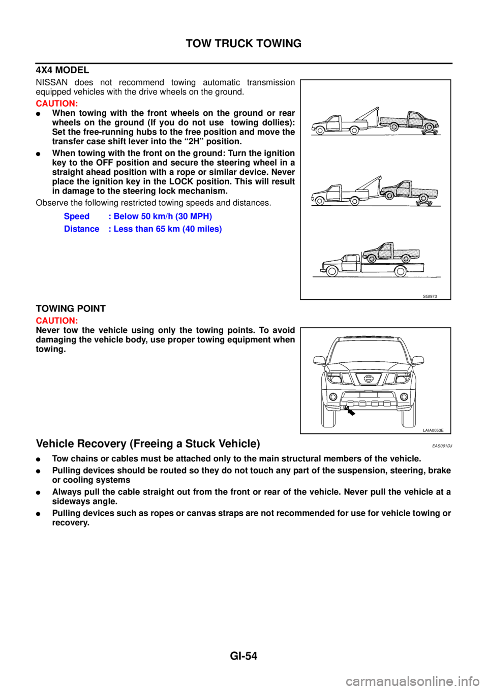
NISSAN does not recommend towing automatic transmission
equipped vehicles with the drive wheels on the ground.
CAUTION:
lWhen towing with the front wheels on the ground or rear
wheels on the ground (If you do not use towing dollies):
Set the free-running hubs to the free position and move the
transfer case shift lever into the “2H” position.
lWhen towing with the front on the ground: Turn the ignition
key to the OFF position and secure the steering wheel in a
straight ahead position with a rope or similar device. Never
place the ignition key in the LOCK position. This will result
in damage to the steering lock mechanism.
Observe the following restricted towing speeds and distances.
TOWING POINT
CAUTION:
Never tow the vehicle using only the towing points. To avoid
damaging the vehicle body, use proper towing equipment when
towing.
Vehicle Recovery (Freeing a Stuck Vehicle)EAS001DJ
lTow chains or cables must be attached only to the main structural members of the vehicle.
lPulling devices should be routed so they do not touch any part of the suspension, steering, brake
or cooling systems
lAlways pull the cable straight out from the front or rear of the vehicle. Never pull the vehicle at a
sideways angle.
lPulling devices such as ropes or canvas straps are not recommended for use for vehicle towing or
recovery.Speed : Below 50 km/h (30 MPH)
Distance : Less than 65 km (40 miles)
SGI973
LAIA0053E
Page 1680 of 3171

GI-58
IDENTIFICATION INFORMATION
IDENTIFICATION PLATE
ENGINE SERIAL NUMBER
TRANSFER SERIAL NUMBER
AUTOMATIC TRANSMISSION NUMBER
MAIB0014E
MAIB0009E
AGI108
PAIA0054E
Page 1754 of 3171
IDX-2
ALPHABETICAL INDEX
Numerics
4LO indicator lamp .............................................TF-16
4LO switch ..............................................TF-56,TF-59
4WD - Wiring diagram .......................................TF-25
4WD shift indicator lamp ....................................TF-16
4WD shift switch .........................TF-16,TF-59,TF-62
4WD system description ....................................TF-15
4WD system diagram ........................................TF-18
4WD warning lamp ............................................TF-17
A
A/C air flow .......................................ATC-30
,MTC-30
A/C compressor clutch removal and installation ...........
ATC-143
,MTC-123
A/C compressor mounting ............ATC-142,MTC-122
A/C compressor precaution ..............ATC-12,MTC-12
A/C compressor special service tool .ATC-16,MTC-16
A/C control operation (auto A/C) .......ATC-28,MTC-28
A/C diagnostic work flow (auto A/C)ATC-103,MTC-95
A/C evaporator ..............................ATC-149,MTC-129
A/C HFC134a (R134a) system precaution .......ATC-4,
MTC-4
A/C HFC134a (R134a) system service procedure .......
ATC-138
,MTC-118
A/C HFC134a (R134a) system service tools ..ATC-16,
MTC-16
A/C HFC134a system service equipment precaution ...
ATC-12
,MTC-12
A/C lubricant (R134a) .......................ATC-24,MTC-24
A/C lubrication oil ..............................ATC-24,MTC-24
A/C operational check .......................ATC-57,MTC-53
A/C self-diagnoses (auto A/C) .......ATC-55,ATC-103,
MTC-51
,MTC-95
A/C service data specification .......ATC-154,MTC-135
A/C trouble diagnoses (auto A/C) .....ATC-33,MTC-33
A/C, A - Wiring diagram ....................ATC-39,MTC-39
A/T fluid checking ......................AT-12,AT-43,MA-29
A/T fluid replacement .............................AT-11,MA-31
A/T fluid temperature sensor ...........................AT-118
A/T IND - Wiring diagram ....................................DI-49
A/T indicator ........................................................DI-48
A/T self-diagnoses .............................................AT-89
A/T shift lock system ........................................AT-212
A/T trouble diagnoses ........................................AT-34
A/T Wiring diagram AT - CAN ............................AT-92
A/T Wiring diagram AT - FTS ..........................AT-119
A/T Wiring diagram AT - MAIN ........................AT-164
A/T Wiring diagram AT - NONDTC ..................AT-174
A/T Wiring diagram AT - PNP/SW ...................AT-100
A/T Wiring diagram AT - STSIG ........................AT-95
A/T Wiring diagram AT - VSS A/T ...................AT-105
ABS - Wiring diagram .....................................BRC-13
Accelerator control system ...............................ACC-2
Accelerator pedal position (APP) sensor ........EC-108,
EC-142
,EC-275
Aiming adjustment ..................................LT-28,LT-85
Air bag ..............................................................SRS-3
Air bag disposal ..............................................SRS-49
Air bleeding (hydraulic clutch) ..............................CL-8
Air cleaner and air duct .....................................EM-15
Air cleaner filter .................................................EM-17
Air cleaner filter replacement ............................MA-25
Air conditioner cut control ..................................EC-20
Air flow meter - See Mass air flow sensor ..........EC-92
Air mix. door motor .........................................ATC-68
Alternator ...........................................................SC-14
Ambient sensor .............................ATC-105,ATC-117
Angular tightening application .............................EM-4
APP2PW - Wiring diagram ..............................EC-229
APPS - Wiring diagram ....................................EC-110
APPS2 - Wiring diagram ..................................EC-144
APPS3 - Wiring diagram ..................................EC-277
ASC/BS - Wiring diagram ................................EC-192
ASC/SW - Wiring diagram ...............................EC-208
ASCBOF - Wiring diagram ...............................EC-331
ASCD ...............................................................EC-355
ASCD (automatic speed control device) ...........ACS-2
ASCD brake switch ...........................EC-189,EC-330
ASCD clutch switch ..........................EC-189,EC-330
ASCD indicator lamp .......................................EC-351
ASCD steering switch ......................................EC-206
ASCIND - Wiring diagram ................................EC-352
ATP switch ..............................................TF-82,TF-85
Auto air conditioner - Wiring diagramATC-39,MTC-39
Auto anti-dazzling inside mirror .......................GW-45
Autolamp ............................................................LT-49
Automatic amplifier ..........................ATC-60,MTC-55
Automatic transmission number ..............GI-58,GI-59
B
Back door trim .....................................................EI-30
BACK/L - Wiring diagram .................................LT-123
Back-up lamp ...................................................LT-123
Back-up lamp switch (M/T) ...................MT-12,MT-19
Ball joint (front) ................................................FSU-15
Barometric pressure (BARO) sensor ...............EC-293
Basic inspection .................................................EC-38
Battery .................................................................SC-5
Baulk ring (M/T) ................................................MT-21
BCM (Body control module) ..............................BCS-3
Blower motor ...ATC-80,ATC-121,MTC-71,MTC-100
Body mounting ....................................BL-189,BL-190
BOOST - Wiring diagram .................................EC-155
Brake booster ....................................................BR-19
Brake fluid level ................................................MA-35
Brake inspection ...............................................MA-35
Brake lines and cables inspection ....................MA-35
Brake master cylinder ........................................BR-17
Brake pedal ..........................................................BR-6
Brake switch ....................................................EC-330
Bulb specifications ...........................................LT-173
Bumper, front ......................................................EI-15
Bumper, rear .......................................................EI-17
Page 1807 of 3171
![NISSAN NAVARA 2005 Repair Workshop Manual LAN-30
[CAN]
CAN COMMUNICATION
CAN Communication Unit
EKS00PDT
Go to CAN system, when selecting your CAN system type from the following table.
´: Applicable
NOTE:
Confirming the presence of the follo NISSAN NAVARA 2005 Repair Workshop Manual LAN-30
[CAN]
CAN COMMUNICATION
CAN Communication Unit
EKS00PDT
Go to CAN system, when selecting your CAN system type from the following table.
´: Applicable
NOTE:
Confirming the presence of the follo](/manual-img/5/57362/w960_57362-1806.png)
LAN-30
[CAN]
CAN COMMUNICATION
CAN Communication Unit
EKS00PDT
Go to CAN system, when selecting your CAN system type from the following table.
´: Applicable
NOTE:
Confirming the presence of the following items helps to identify CAN system type.
lWith automatic air conditioner
lWith electronic locking rear differential
Body type Truck
Axle 2WD 4WD
Engine YD25DDTi
Transmission M/T A/T M/T A/T
Brake control ABS
Automatic air conditioner´´´´ ´´´´´´´´
Electronic locking rear
differential´´´´´
Navigation system´´ ´´ ´´
CAN system
typeLHD1234567
8 9 10 11 12 13 14 15
RHD–––––1617
CAN system
trouble diagnosisLHDLAN
-44
LAN
-56
LAN
-68
LAN
-82
LAN
-96
LAN
-112
LAN
-125LAN
-139
LAN
-152
LAN
-166
LAN
-181
LAN
-198
LAN
-213
LAN
-230
LAN
-248RHD–––––LAN-267
LAN
-279
PKIC2534E
PKIC2535E
Page 2280 of 3171
DESCRIPTION
MA-5
C
D
E
F
G
H
I
J
K
MA
B
MA
DESCRIPTIONPFP:00000
Pre-Delivery Inspection ItemsELS001K2
Shown below are Pre-delivery Inspection Items required for the new vehicle. It is recommended that
necessary items other than those listed here be added, paying due regard to the conditions in each
country.
Perform applicable items on each model. Consult text of this section for specifications.
Install vehicle protection kit
Fit all accessories ordered (if applicable) (e.g. towbar, audio, navigation, air conditioner, styling kit)
UNDER HOOD — engine off
Check coolant level and cooling system for leaks
Charge battery and check terminals for condition
Check drive belts tension
Check fuel filter for water or dust (diesel only) and fuel system for leaks
Check engine oil level and for oil leaks
Check brake and clutch fluid levels and fluid lines for leaks
Check and top up washer reservoirs
Check power steering fluid level and fluid lines for leaks (if applicable)
Check air conditioning system for gas leaks (if applicable)
ON INSIDE AND OUTSIDE
Install transit fuse if removed for vehicle storage
Check instruments, gauges, lamps, horn and accessories for operation
Check wipers and washers for operation and adjustment
Check interior and door mirrors and sun visors for operation
Set radio code and set clock
Check parking brake adjustment
Check clutch pedal adjustment
Check steering lock operation
Check seat adjusters and seat belts for operation
Check all windows for operation and alignment
Check mouldings, trim and fittings for fit and alignment
Check weatherstrips for fit and adhesion
Check hood, trunk lid, door panels and fuel lid for fit and alignment
Check latches, keys, remote key, door locks and remote trunk lid and fuel lid release for operation
Check wheel nut torques
Check tyre pressure (incl. spare tyre)
Check tool kit and jack for operation
Check automatic transmission/transaxle starter inhibitor (if applicable)
Check sunroof for operation and alignment (if applicable)
UNDER BODY
Check manual transmission/transaxle, differential and transfer box for oil level and oil leaks
Tighten bolts and nuts steering linkage and gear box, axle/suspension parts, propeller and exhaust system
Check brake and clutch lines, and oil/fluid reservoirs for leaks
Remove front suspension spacer blocks (if applicable)
Check body mounting torque (if applicable)
Page 2281 of 3171
MA-6
DESCRIPTION
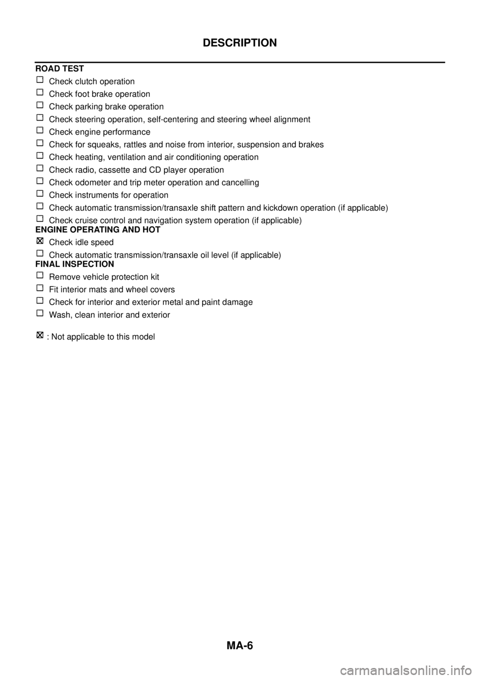
ROAD TEST
Check clutch operation
Check foot brake operation
Check parking brake operation
Check steering operation, self-centering and steering wheel alignment
Check engine performance
Check for squeaks, rattles and noise from interior, suspension and brakes
Check heating, ventilation and air conditioning operation
Check radio, cassette and CD player operation
Check odometer and trip meter operation and cancelling
Check instruments for operation
Check automatic transmission/transaxle shift pattern and kickdown operation (if applicable)
Check cruise control and navigation system operation (if applicable)
ENGINE OPERATING AND HOT
Check idle speed
Check automatic transmission/transaxle oil level (if applicable)
FINAL INSPECTION
Remove vehicle protection kit
Fit interior mats and wheel covers
Check for interior and exterior metal and paint damage
Wash, clean interior and exterior
: Not applicable to this model