Page 2786 of 3171

REAR FINAL DRIVE ASSEMBLY
RFD-83
[WITH ELECTRONIC LOCKING DIFFERENTIAL]
C
E
F
G
H
I
J
K
L
MA
B
RFD
ASSEMBLY INSPECTION AND ADJUSTMENT
lBefore inspection and adjustment, drain gear oil.
Total Preload Torque
1. Rotate drive pinion back and forth 2 to 3 times to check for unusual noise and rotation malfunction.
2. Rotate drive pinion at least 20 times to check for smooth operation of the bearing.
3. Turn drive pinion in both directions several times to set bearing
rollers.
4. Measure total preload with preload gauge.
NOTE:
Total preload torque = Pinion bearing preload torque + Side bearing preload torque
lIf measured value is out of the specification, disassemble it to check and adjust each part. Adjust pinion
bearing preload and side bearing preload.
Adjust pinion bearing preload first, then adjust side bearing preload.
Tooth Contact
Checking gear tooth contact pattern is necessary to verify correct relationship between drive gear and drive
pinion. Gears which are not positioned in proper arrangement may be noisy and/or have a short life. Check
gear tooth contact pattern to obtain the best contact for low noise and long life.
1. Remove carrier cover. Refer toRFD-86, "
Differential Assembly".
2. Thoroughly clean drive gear and drive pinion teeth.
3. Apply red lead to drive gear.
CAUTION:
Applyredleadtoboththefacesof3to4gearsat4loca-
tions evenly spaced on drive gear.Tool number : ST3127S000
To ta l p r e l o a d
Gear ratio 3.538 Type:
2.34 - 4.34 N·m (0.24 - 0.44 kg-m, 21- 38 in-lb)
Gear ratio 3.692 Type:
2.32 - 4.34 N·m (0.24 - 0.44 kg-m, 21 - 38 in-lb)
When the preload torque is greater than specification
On pinion bearings: Replace collapsible spacer.
On side bearings: Loosen side bearing adjuster.
When the preload torque is less than specification
On pinion bearings: Tighten drive pinion lock nut.
On side bearings: Tighten side bearing adjuster.
PDIA0309E
SDIA2623E
Page 2803 of 3171
RFD-100
[WITH ELECTRONIC LOCKING DIFFERENTIAL]
SERVICE DATA AND SPECIFICATIONS (SDS)
SERVICE DATA AND SPECIFICATIONS (SDS)
PFP:00030
General SpecificationsEDS003BH
Inspection and AdjustmentEDS003BI
PRELOAD TORQUE
Unit: N·m (kg-m, in-lb)
BACKLASH
Unit: mm (in)
COMPANION FLANGE RUNOUT
Unit: mm (in) Applied modelYD25DDTi
4WD
5A/T 6M/T
Final drive modelM226
Gear ratio 3.538 3.692
Number of pinion gears 2
Number of teeth (Drive gear / drive pinion) 46/13 48/13
Oil capacity (Approx.)
(lmp pt)2.01 (3-1/2)
Drive pinion adjustment spacer type Collapsible
ItemStandard
Gear ratio: 3.538 type Gear ratio: 3.692 type
Total preload 2.34 - 4.34 (0.24 - 0.44, 21 - 38) 2.32 - 4.34 (0.24 - 0.44, 21 - 38)
Pinion bearing preload 1.7 - 3.1 (0.18 - 0.31, 15 - 27)
Item Standard
Drive gear to drive pinion gear 0.08 - 0.13 (0.0031 - 0.0051)
Item Runout limit
Companion flange face 0.10 (0.0039) or less
Inner side of companion flange 0.13 (0.0051) or less
Page 2912 of 3171
PRECAUTIONS
SRS-3
C
D
E
F
G
I
J
K
L
MA
B
SRS
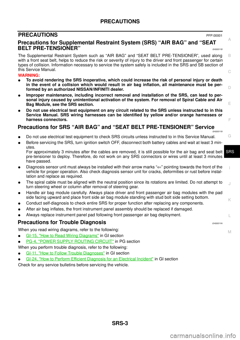
PRECAUTIONSPFP:00001
Precautions for Supplemental Restraint System (SRS) “AIR BAG” and “SEAT
BELT PRE-TENSIONER”
EHS001Y8
The Supplemental Restraint System such as “AIR BAG” and “SEAT BELT PRE-TENSIONER”, used along
with a front seat belt, helps to reduce the risk or severity of injury to the driver and front passenger for certain
types of collision. Information necessary to service the system safely is included in the SRS and SB section of
this Service Manual.
WARNING:
lTo avoid rendering the SRS inoperative, which could increase the risk of personal injury or death
in the event of a collision which would result in air bag inflation, all maintenance must be per-
formed by an authorized NISSAN/INFINITI dealer.
lImproper maintenance, including incorrect removal and installation of the SRS, can lead to per-
sonal injury caused by unintentional activation of the system. For removal of Spiral Cable and Air
Bag Module, see the SRS section.
lDo not use electrical test equipment on any circuit related to the SRS unless instructed to in this
Service Manual. SRS wiring harnesses can be identified by yellow and/or orange harnesses or
harness connectors.
Precautions for SRS “AIR BAG” and “SEAT BELT PRE-TENSIONER” ServiceEHS001Y9
lDo not use electrical test equipment to check SRS circuits unless instructed to in this Service Manual.
lBefore servicing the SRS, turn ignition switch OFF, disconnect both battery cables and wait at least 3 min-
utes.
For approximately 3 minutes after the cables are removed, it is still possible for the air bag and seat belt
pre-tensioner to deploy. Therefore, do not work on any SRS connectors or wires until at least 3 minutes
have passed.
lDiagnosis sensor unit must always be installed with their arrow marks “Ü” pointing towards the front of the
vehicle for proper operation. Also check diagnosis sensor unit for cracks, deformities or rust before instal-
lation and replace as required.
lThe spiral cable must be aligned with the neutral position since its rotations are limited. Do not attempt to
turn steering wheel or column after removal of steering gear.
lHandle air bag module carefully. Always place driver and front passenger air bag modules with the pad
side facing upward and place front side air bag module standing with stud bolt side setting bottom.
lConduct self-diagnosis to check entire SRS for proper function after replacing any components.
lAfter air bag inflates, the front instrument panel assembly should be replaced if damaged.
lAlways replace instrument panel pad following front passenger air bag deployment.
Precautions for Trouble DiagnosisEHS001YA
When you read wiring diagrams, refer to the following:
lGI-15, "How to Read Wiring Diagrams"in GI section
lPG-4, "POWER SUPPLY ROUTING CIRCUIT"in PG section
When you perform trouble diagnosis, refer to the following:
lGI-11, "How to Follow Trouble Diagnoses"in GI section
lGI-24, "How to Perform Efficient Diagnosis for an Electrical Incident"in GI section
Check for any service bulletins before servicing the vehicle.
Page 2975 of 3171
TF-8
PREPARATION
PREPARATION
PFP:00002
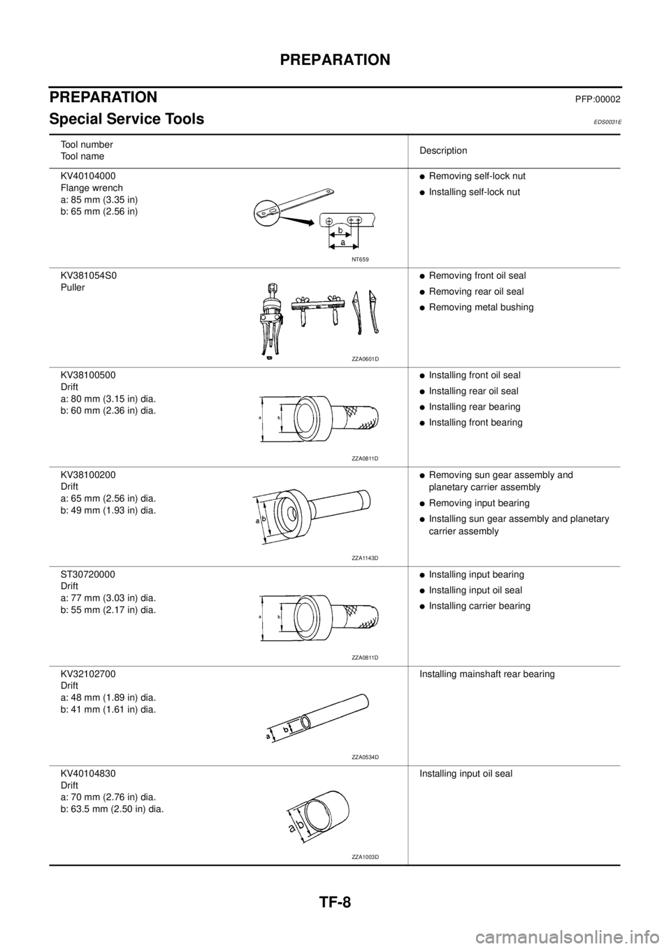
Special Service ToolsEDS0031E
Tool number
Tool nameDescription
KV40104000
Flange wrench
a: 85 mm (3.35 in)
b: 65 mm (2.56 in)
lRemoving self-lock nut
lInstalling self-lock nut
KV381054S0
Puller
lRemoving front oil seal
lRemoving rear oil seal
lRemoving metal bushing
KV38100500
Drift
a: 80 mm (3.15 in) dia.
b: 60 mm (2.36 in) dia.
lInstalling front oil seal
lInstalling rear oil seal
lInstalling rear bearing
lInstalling front bearing
KV38100200
Drift
a: 65 mm (2.56 in) dia.
b: 49 mm (1.93 in) dia.
lRemoving sun gear assembly and
planetary carrier assembly
lRemoving input bearing
lInstalling sun gear assembly and planetary
carrier assembly
ST30720000
Drift
a: 77 mm (3.03 in) dia.
b: 55 mm (2.17 in) dia.
lInstalling input bearing
lInstalling input oil seal
lInstalling carrier bearing
KV32102700
Drift
a: 48 mm (1.89 in) dia.
b: 41 mm (1.61 in) dia.Installing mainshaft rear bearing
KV40104830
Drift
a: 70 mm (2.76 in) dia.
b: 63.5 mm (2.50 in) dia.Installing input oil seal
NT659
ZZA0601D
ZZA0811D
ZZA1143D
ZZA0811D
ZZA0534D
ZZA1003D
Page 2978 of 3171
NOISE, VIBRATION AND HARSHNESS (NVH) TROUBLESHOOTING
TF-11
C
E
F
G
H
I
J
K
L
MA
B
TF
NOISE, VIBRATION AND HARSHNESS (NVH) TROUBLESHOOTINGPFP:00003
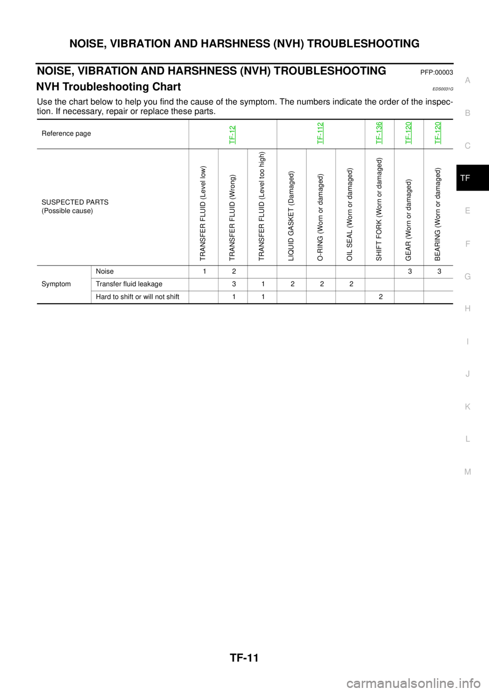
NVH Troubleshooting ChartEDS0031G
Use the chart below to help you find the cause of the symptom. The numbers indicate the order of the inspec-
tion. If necessary, repair or replace these parts.
Reference page
TF-12TF-112TF-136TF-120TF-120
SUSPECTED PARTS
(Possible cause)
TRANSFER FLUID (Level low)
TRANSFER FLUID (Wrong)
TRANSFER FLUID (Level too high)
LIQUID GASKET (Damaged)
O-RING (Worn or damaged)
OIL SEAL (Worn or damaged)
SHIFT FORK (Worn or damaged)
GEAR (Worn or damaged)
BEARING (Worn or damaged)
SymptomNoise 1 2 3 3
Transfer fluid leakage 3 1 2 2 2
Hard to shift or will not shift 1 1 2
Page 3105 of 3171
TF-138
SERVICE DATA AND SPECIFICATIONS (SDS)
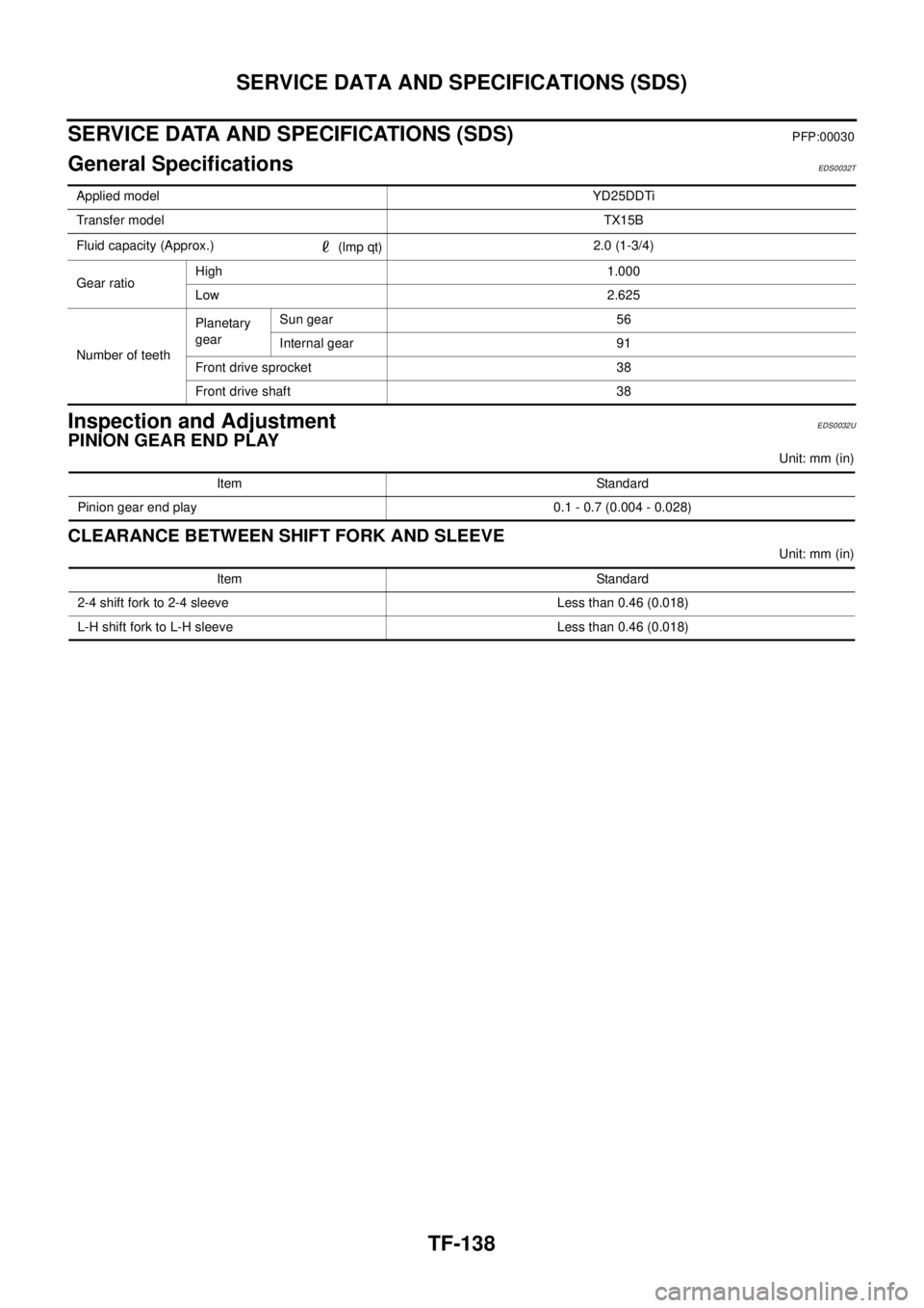
SERVICE DATA AND SPECIFICATIONS (SDS)
PFP:00030
General SpecificationsEDS0032T
Inspection and AdjustmentEDS0032U
PINION GEAR END PLAY
Unit: mm (in)
CLEARANCE BETWEEN SHIFT FORK AND SLEEVE
Unit: mm (in) Applied modelYD25DDTi
Transfer modelTX15B
Fluid capacity (Approx.)
(lmp qt)2.0 (1-3/4)
Gear ratioHigh 1.000
Low 2.625
Number of teethPlanetary
gearSun gear 56
Internal gear 91
Front drive sprocket 38
Front drive shaft 38
Item Standard
Pinion gear end play 0.1 - 0.7 (0.004 - 0.028)
Item Standard
2-4 shift fork to 2-4 sleeve Less than 0.46 (0.018)
L-H shift fork to L-H sleeve Less than 0.46 (0.018)