2005 NISSAN NAVARA gear ratio
[x] Cancel search: gear ratioPage 2629 of 3171
PS-2
PRECAUTIONS
PRECAUTIONS
PFP:00001
Precautions for Supplemental Restraint System (SRS) “AIR BAG” and “SEAT
BELT PRE-TENSIONER”
EGS001M0
The Supplemental Restraint System such as “AIR BAG” and “SEAT BELT PRE-TENSIONER”, used along
with a front seat belt, helps to reduce the risk or severity of injury to the driver and front passenger for certain
types of collision. Information necessary to service the system safely is included in the SRS and SB section of
this Service Manual.
WARNING:
lTo avoid rendering the SRS inoperative, which could increase the risk of personal injury or death
in the event of a collision which would result in air bag inflation, all maintenance must be per-
formed by an authorized NISSAN/INFINITI dealer.
lImproper maintenance, including incorrect removal and installation of the SRS, can lead to per-
sonal injury caused by unintentional activation of the system. For removal of Spiral Cable and Air
Bag Module, see the SRS section.
lDo not use electrical test equipment on any circuit related to the SRS unless instructed to in this
Service Manual. SRS wiring harnesses can be identified by yellow and/or orange harnesses or
harness connectors.
Precautions for Steering SystemEGS001L9
lIn case of removing steering gear assembly, make the final tightening with grounded and unloaded vehi-
cle condition, and then check wheel alignment.
lObserve the following precautions when disassembling.
–Before disassembly, thoroughly clean the outside of the unit.
–Disassembly should be done in a clean work area. It is important to prevent the internal parts from becom-
ing contaminated by dirt or other foreign matter.
–For easier and proper assembly, place disassembled parts in order on a parts rack.
–Use nylon cloth or paper towels to clean the parts; common shop rags can leave lint that might interfere
with their operation.
–Do not reuse non-reusable parts.
–Before assembling, apply the specified grease to the directed parts.
Page 2632 of 3171
NOISE, VIBRATION, AND HARSHNESS (NVH) TROUBLESHOOTING
PS-5
C
D
E
F
H
I
J
K
L
MA
B
PS
NOISE, VIBRATION, AND HARSHNESS (NVH) TROUBLESHOOTINGPFP:00003
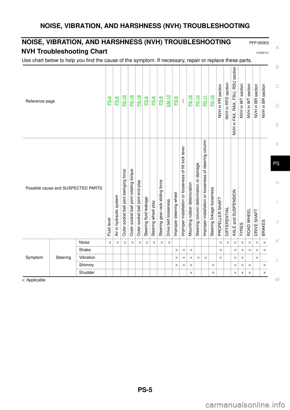
NVH Troubleshooting ChartEGS001LC
Use chart below to help you find the cause of the symptom. If necessary, repair or replace these parts.
´: ApplicableReference page
PS-6PS-6PS-18PS-18PS-18PS-6PS-8PS-8EM-12PS-8—
PS-18PS-12PS-11PS-16
NVHinPRsection
NVH in RFD section
NVH in FAX, RAX, FSU, RSU section
NVH in WT section
NVH in WT section
NVHinBRsection
NVHinBRsection
Possible cause and SUSPECTED PARTS
Fluid level
Air in hydraulic system
Outer socket ball joint swinging force
Outer socket ball joint rotating torque
Outer socket ball joint end play
Steering fluid leakage
Steering wheel play
Steering gear rack sliding force
Drive belt looseness
Improper steering wheel
Improper installation or looseness of tilt lock lever
Mounting rubber deterioration
Steering column deformation or damage
Improper installation or looseness of steering column
Steering linkage looseness
PROPELLER SHAFT
DIFFERENTIAL
AXLE and SUSPENSION
TYRES
ROAD WHEEL
DRIVE SHAFT
BRAKES
Symptom SteeringNoise´ ´ ´´´´´ ´ ´ ´´´´´´ ´
Shake´´´ ´ ´´´´ ´
Vibration´´´´´ ´ ´´ ´
Shimmy´´´ ´ ´´´ ´
Shudder´ ´ ´´´ ´
Page 2704 of 3171
RFD-1
REAR FINAL DRIVE
D DRIVELINE/AXLE
CONTENTS
C
E
F
G
H
I
J
K
L
M
SECTIONRFD
A
B
RFD
REAR FINAL DRIVE
WITH LIMITED SLIP DIFFERENTIAL
PRECAUTIONS .......................................................... 3
Limited Slip Differential (LSD) Performance Judge-
ment ......................................................................... 3
METHOD FOR TROUBLESHOOTING ................. 3
Service Notice or Precautions .................................. 3
PREPARATION ........................................................... 4
Special Service Tools ............................................... 4
Commercial Service Tools ........................................ 5
NOISE, VIBRATION, AND HARSHNESS (NVH)
TROUBLESHOOTING ................................................ 7
NVH Troubleshooting Chart ..................................... 7
DESCRIPTION ............................................................ 8
Cross-Sectional View ............................................... 8
DIFFERENTIAL GEAR OIL ........................................ 9
Changing Differential Gear Oil ................................. 9
DRAINING ............................................................. 9
FILLING ................................................................. 9
Checking Differential Gear Oil .................................. 9
OIL LEAKAGE AND OIL LEVEL ........................... 9
FRONT OIL SEAL .................................................... 10
Removal and Installation ........................................ 10
REMOVAL ........................................................... 10
INSTALLATION .................................................... 11
CARRIER COVER .................................................... 13
Removal and Installation ........................................ 13
REMOVAL ........................................................... 13
INSTALLATION ................................................... 13
REAR FINAL DRIVE ASSEMBLY ............................ 14
Removal and Installation ........................................ 14
REMOVAL ........................................................... 14
INSTALLATION ................................................... 14
Disassembly and Assembly ................................... 15
COMPONENTS .................................................. 15
ASSEMBLY INSPECTION AND ADJUSTMENT... 16
DISASSEMBLY ................................................... 19
INSPECTION AFTER DISASSEMBLY ............... 22
SELECTION ADJUSTING WASHERS ............... 23
ASSEMBLY ......................................................... 24SERVICE DATA AND SPECIFICATIONS (SDS) ...... 31
General Specifications ............................................ 31
Inspection and Adjustment ..................................... 31
PRELOAD TORQUE ........................................... 31
BACKLASH ......................................................... 31
COMPANION FLANGE RUNOUT ....................... 31
SELECTIVE PARTS ............................................ 32
WITH ELECTRONIC LOCKING DIFFEREN-
TIAL
PRECAUTIONS ........................................................ 33
Precautions for Supplemental Restraint System
(SRS)“AIRBAG”and“SEATBELTPRE-TEN-
SIONER” ................................................................. 33
Precautions for Differential Case Assembly and Dif-
ferential Lock Control Unit Replacement ................ 33
CHECK DIFF LOCK INDICATOR LAMP ............. 33
METHOD FOR ADJUSTMENT ........................... 34
Precautions ............................................................. 34
Service Notice or Precaution .................................. 35
Wiring Diagrams and Trouble Diagnosis ................ 35
PREPARATION ......................................................... 36
Special Service Tools ............................................. 36
Commercial Service Tools ...................................... 37
NOISE, VIBRATION AND HARSHNESS (NVH)
TROUBLESHOOTING .............................................. 39
NVH Troubleshooting Chart ................................... 39
DIFFERENTIAL GEAR OIL ...................................... 40
Changing Differential Gear Oil ................................ 40
DRAINING ........................................................... 40
FILLING ............................................................... 40
Checking Differential Gear Oil ................................ 40
OIL LEAKAGE AND OIL LEVEL ......................... 40
DIFFERENTIAL LOCK SYSTEM .............................. 41
Cross-sectional View .............................................. 41
Differential Lock Operation ..................................... 42
System Description ................................................. 42
DIFFERENTIAL LOCK SOLENOID .................... 42
DIFFERENTIAL LOCK POSITION SWITCH ....... 42
Page 2710 of 3171

NOISE, VIBRATION, AND HARSHNESS (NVH) TROUBLESHOOTING
RFD-7
[WITH LIMITED SLIP DIFFERENTIAL]
C
E
F
G
H
I
J
K
L
MA
B
RFD
NOISE, VIBRATION, AND HARSHNESS (NVH) TROUBLESHOOTINGPFP:00003
NVH Troubleshooting ChartEDS00392
Use the chart below to help you find the cause of the symptom. If necessary, repair or replace these parts.
´: ApplicableReference page
RFD-22, "
INSPECTION AFTER DISASSEMBLY
"
RFD-16, "
Tooth Contact
"
RFD-22, "
INSPECTION AFTER DISASSEMBLY
"
RFD-17, "
Backlash
"
RFD-18, "
Companion Flange Runout
"
RFD-9, "
Checking Differential Gear Oil
"
PR-2, "
NVH Troubleshooting Chart
"
RAX-5, "
NVH Troubleshooting Chart
",RSU-3, "
NVH Troubleshooting Chart
"
WT-2, "
NVH Troubleshooting Chart
"
RAX-5, "
NVH Troubleshooting Chart
"
BR-5, "
NVH Troubleshooting Chart
"
PS-5, "
NVH Troubleshooting Chart
"
Possible cause and SUSPECTED PARTS
Gear tooth rough
Gear contact improper
Tooth surfaces worn
Backlash incorrect
Companion flange excessive runout
Gear oil improper
PROPELLER SHAFT
AXLE AND SUSPENSION
TIRES
ROAD WHEEL
AXLE SHAFT
BRAKES
STEERING
Symptom Noise´´´´´´´´´´´´´
Page 2719 of 3171

RFD-16
[WITH LIMITED SLIP DIFFERENTIAL]
REAR FINAL DRIVE ASSEMBLY
ASSEMBLY INSPECTION AND ADJUSTMENT
lBefore inspection and adjustment, drain gear oil.
Total Preload Torque
1. Rotate drive pinion back and forth 2 to 3 times to check for unusual noise and rotation malfunction.
2. Rotate drive pinion at least 20 times to check for smooth operation of the bearing.
3. Turn drive pinion in both directions several times to set bearing
rollers.
4. Measure total preload with preload gauge.
NOTE:
Total preload torque = Pinion bearing preload torque + Side bearing preload torque
lIf measured value is out of the specification, disassemble it to check and adjust each part. Adjust pinion
bearing preload and side bearing preload.
Adjust pinion bearing preload first, then adjust side bearing preload.
Tooth Contact
Checking gear tooth contact pattern is necessary to verify correct relationship between drive gear and drive
pinion. Gears which are not positioned in proper arrangement may be noisy and/or have a short life. Check
gear tooth contact pattern to obtain the best contact for low noise and long life.
1. Remove carrier cover. Refer toRFD-13, "
Removal and Installation".
2. Thoroughly clean drive gear and drive pinion teeth.
3. Apply red lead to drive gear.
CAUTION:
Apply red lead to both the faces of 3 to 4 gears at 4 loca-
tions evenly spaced on drive gear.Tool number : ST3127S000
To ta l p r e l o a d
Gear ratio 3.357 Type:
2.38 - 4.46 N·m (0.25 - 0.45 kg-m, 21- 39 in-lb)
Gear ratio 3.538 Type:
2.34 - 4.34 N·m (0.24 - 0.44 kg-m, 21- 38 in-lb)
Gear ratio 3.692 Type:
2.32 - 4.34 N·m (0.24 - 0.44 kg-m, 21 - 38 in-lb)
When the preload torque is greater than specification
On pinion bearings: Replace collapsible spacer.
On side bearings: Loosen side bearing adjuster.
When the preload torque is less than specification
On pinion bearings: Tighten drive pinion lock nut.
On side bearings: Tighten side bearing adjuster.
PDIA0309E
PDIA0321E
Page 2734 of 3171

SERVICE DATA AND SPECIFICATIONS (SDS)
RFD-31
[WITH LIMITED SLIP DIFFERENTIAL]
C
E
F
G
H
I
J
K
L
MA
B
RFD
SERVICE DATA AND SPECIFICATIONS (SDS)PFP:00030
General SpecificationsEDS0039A
*: Option
Inspection and AdjustmentEDS0039B
PRELOAD TORQUE
Unit: N·m (kg-m, in-lb)
BACKLASH
Unit: mm (in)
COMPANION FLANGE RUNOUT
Unit: mm (in) Applied modelYD25DDTi
2WD 4WD
6M/T 5A/T 6M/T 5A/T
Grade SE, XE SE SE, XE* XE SE
Final drive modelM226
Gear ratio 3.538 3.357 3.692 3.538
Number of pinion gears 2
Number of teeth (Drive gear / drive pinion) 46/13 47/14 48/13 46/13
Oil capacity (Approx.)
(lmp pt)2.01 (3-1/2)
Drive pinion adjustment spacer type Collapsible
ItemSpecification
Gear ratio 3.357 type Gear ratio 3.538 type Gear ratio 3.692 type
To t a l p r e l o a d2.38 - 4.46
(0.25-0.45,21-39)2.34 - 4.34
(0.24 - 0.44, 21 - 38)2.32 - 4.34
(0.24 - 0.44, 21 - 38)
Pinion bearing preload 1.7 - 3.1 (0.18 - 0.31, 15 - 27)
Item Standard
Drive gear to drive pinion gear 0.08 - 0.13 (0.0031 - 0.0051)
Item Runout limit
Companion flange face 0.10 (0.0039) or less
Inner side of companion flange 0.13 (0.0051) or less
Page 2742 of 3171

NOISE, VIBRATION AND HARSHNESS (NVH) TROUBLESHOOTING
RFD-39
[WITH ELECTRONIC LOCKING DIFFERENTIAL]
C
E
F
G
H
I
J
K
L
MA
B
RFD
NOISE, VIBRATION AND HARSHNESS (NVH) TROUBLESHOOTINGPFP:00003
NVH Troubleshooting ChartEDS003AM
Use the chart below to help you find the cause of the symptom. If necessary, repair or replace these parts.
´: ApplicableReference page
RFD-90, "
INSPECTION AFTER DISASSEMBLY
"
RFD-83, "
Tooth Contact
"
RFD-90, "
INSPECTION AFTER DISASSEMBLY
"
RFD-84, "
Backlash
"
RFD-85, "
Companion Flange Runout
"
RFD-40, "
Checking Differential Gear Oil
"
PR-2, "
NVH Troubleshooting Chart
"
RAX-5, "
NVH Troubleshooting Chart
",RSU-3, "
NVH Troubleshooting Chart
"
WT-2, "
NVH Troubleshooting Chart
"
RAX-5, "
NVH Troubleshooting Chart
"
BR-5, "
NVH Troubleshooting Chart
"
PS-5, "
NVH Troubleshooting Chart
"
Possible cause and SUSPECTED PARTS
Gear tooth rough
Gear contact improper
Tooth surfaces worn
Backlash incorrect
Companion flange excessive runout
Gear oil improper
PROPELLER SHAFT
AXLE AND SUSPENSION
TIRES
ROAD WHEEL
AXLE SHAFT
BRAKES
STEERING
Symptom Noise´´´´´´´´´´´´´
Page 2745 of 3171

RFD-42
[WITH ELECTRONIC LOCKING DIFFERENTIAL]
DIFFERENTIAL LOCK SYSTEM
Differential Lock Operation
EDS003AQ
1. Differential lock solenoid operates pressure plate.
2. Pressure plate presses cam ring.
3. Engage cam ring and side gear, and then differential is locked.
System DescriptionEDS003AR
DIFFERENTIAL LOCK SOLENOID
It is operated by signal from differential lock control unit, and it operates pressure plate so as to switch lock/
unlock.
DIFFERENTIAL LOCK POSITION SWITCH
It detects that differential is in lock or unlock by pressure plate position, and sends it to differential lock control
unit.
DIFFERENTIAL LOCK CONTROL UNIT
lDifferential lock control unit controls differential lock solenoid by input signals of each sensor and each
switch.
lAs a fail-safe function, differential lock disengages, if malfunction is detected in differential lock system.
lSelf-diagnosis can be done with CONSULT-II.
DIFFERENTIAL LOCK MODE SWITCH
Able to select differential lock and unlock.
DIFF LOCK INDICATOR LAMP
The following is the indications of indicator lamp.
NOTE:
Differential lock standby condition is the condition that differential lock mode switch is ON and differential is unlocked.
SDIA2498E
Condition DIFF LOCK indicator lamp
Differential lock/unlock ON/OFF
Differential lock standby condition Flashing: 1 time/2 seconds
Differential lock system malfunction OFF (Even if differential lock mode switch is turned ON)
Lamp checkTurns ON when ignition switch is turned ON.
Turns OFF after engine start.