Page 1402 of 1500
AUTO-CRUISE CONTROL
ENGINE AND EMISSION CONTROL17-71
ON-VEHICLE SERVICE
AUTO-CRUISE CONTROL SWITCH CHECKM1172001200054
AUTO-CRUISE CONTROL MAIN SWITCH CHECK
1. Turn the ignition switch to the "ON" position.
2. Check that the "CRUISE" indicator lamp within the
combination meter illuminates when the "CRUISE" (MAIN)
switch is switched "ON".
AUTO-CRUISE CONTROL SETTING
1. Switch "ON" the "CRUISE" (MAIN) switch.
2. Drive at the desired speed, above approximately 40 km/h.
3. Push the auto-cruise control switch in the direction of the
arrow.
4. Check to be sure that when the switch is released the speed
is the desired constant speed.
NOTE: If the vehicle speed decreases to approximately 15
km/h below the set speed because of climbing a hill for
example, it is normal for the auto-cruise control to be can-
celled.
Page 1405 of 1500
AUTO-CRUISE CONTROL
ENGINE AND EMISSION CONTROL17-74
THROTTLE POSITION SENSOR
Refer to GROUP 13A, On-vehicle Service Throttle Actuator
Control Motor Check 13A-671 (3.8L engine).
If the air intake duct is removed from the throttle
body take great care to keep fingers away from the
throttle plate. The drive motor has very high torque
and is capable of random movement at any time. Do
not under any circumstance activate the throttle plate
by hand.
When removing the throttle body from the intake
manifold disconnect the wiring first.During replace-
ment connect the wiring last.
Do not activate the throttle body using a DC supply to
test the motor, as permanent damage to the throttle
body will result.
TRANSMISSION INHIBITOR SWITCH ("N"
POSITION)
Refer to GROUP 23A, On-vehicle Service Essential Service
P.23A-294.
Page 1406 of 1500
AUTO-CRUISE CONTROL
ENGINE AND EMISSION CONTROL17-75
AUTO-CRUISE CONTROL
REMOVAL AND INSTALLATIONM1172001400467
Before removal of the air bag module, refer to GROUP 52B, SRS Service Precautions
P.52B-16 and GROUP 52B, Air Bag Module and Clock Spring P.52B-237.
CONTROL SWITCH REMOVAL
STEPS
1. AIR BAG MODULE
SIDE> (REFER TO GROUP 52B, AIR
BAG MODULES AND CLOCK
SPRING P.52B-237)
2. STEERING WHEEL ASSEMBLY
(REFER TO GROUP 37, STEERING
WHEEL P.37-23)
3. LOWER COVER CAP
4. AUTO-CRUISE CONTROL SWITCH
CONTROL UNIT REMOVAL
5. Engine ECU [REFER TO GROUP
13A, Engine ECU 13A-675] SENSOR REMOVAL STEPS
6. TRANSMISSION INHIBITOR
SWITCH (REFER TO GROUP 23B,
AUTOMATIC TRANSMISSION)
7. THROTTLE BODY (BUILT-IN
THROTTLE POSITION SENSOR
AND THROTTLE ACTUATOR
CONTROL MOTOR) (REFER TO
GROUP 13A, THROTTLE BODY
13A-660)
8. ACCELERATOR PEDAL (BUILT-IN
ACCELERATOR PEDAL POSITION
SENSOR) (REFER TO GROUP 17,
ACCELERATOR PEDAL P.17-9)
9. STOPLIGHT SWITCH (REFER TO
GROUP 35A, BRAKE PEDAL
P.35A-24)
Page 1407 of 1500

EMISSION CONTROL
ENGINE AND EMISSION CONTROL17-76
EMISSION CONTROL
GENERAL DESCRIPTIONM1173000100314
The emission control system consists of the fol-
lowing subsystems:
Positive crankcase ventilation system
Evaporative emission system
Exhaust emission control system
DIAGNOSISM1173000700112
SPECIAL TOOLSM1173000600193
SYMPTOM PROBABLE CAUSE REMEDY
Engine will not start or hard
to startVacuum hose disconnected or damaged Repair or replace
Malfunction of the evaporative emission
purge solenoidRepair or replace
Rough idle or engine stalls
Vacuum hose disconnected or damaged. Repair or replace
Malfunction of the positive crankcase
ventilation valveReplace
Malfunction of the purge control system Check the system; If there is a
problem, check its component
parts.
Excessive oil consumption Positive crankcase ventilation line
cloggedCheck positive crankcase
ventilation system
TOOL TOOL NUMBER AND
NAMESUPERSESSION APPLICATION
MB995061
Purge flow indicatorMLR6890A
Part of MIT280220Inspection of purge
control system
MD998770
Oxygen sensor wrenchMD998770-01 or General
service toolRemoval/installation of
heated oxygen sensor
Page 1416 of 1500
SPECIFICATIONS
ENGINE AND EMISSION CONTROL17-85
SPECIFICATIONS
FASTENER TIGHTENING SPECIFICATIONSM1173006400324
SERVICE SPECIFICATIONSM1173000300545
ITEM SPECIFICATION
Auto-cruise control system
Lower cover cap bolt 9.0
2.0 Nm (80 17 in-lb)
Steering wheel assembly nut 41
8 Nm (30 6 ft-lb)
Engine control system
Accelerator pedal assembly nut 13
2 Nm ( 111 22 in-lb)
ITEMSSTANDARD VALUE
Engine control system
Curb idle speed r/min 3.8L Engine 680
100
Emission control system
Purge flow cm
3/s (SCFH) [at 80 95C (176 205F) with sudden revving]20 (2.5)
Evaporative emission purge solenoid coil resistance [at 20
C)] 16
Page 1418 of 1500

26-1
GROUP 26
FRONT AXLE
CONTENTS
GENERAL DESCRIPTION. . . . . . . . .26-2
FRONT AXLE DIAGNOSIS . . . . . . . .26-2
TROUBLESHOOTING STRATEGY . . . . . . 26-2
SYMPTOM CHART. . . . . . . . . . . . . . . . . . . 26-3
SYMPTOM PROCEDURES . . . . . . . . . . . . 26-3
SPECIAL TOOLS . . . . . . . . . . . . . . . .26-4
ON-VEHICLE SERVICE . . . . . . . . . . .26-8
WHEEL BEARING END PLAY CHECK . . . 26-8
HUB BOLT REPLACEMENT . . . . . . . . . . . 26-8
FRONT AXLE HUB ASSEMBLY . . . .26-9
REMOVAL AND INSTALLATION . . . . . . . . 26-9
INSPECTION. . . . . . . . . . . . . . . . . . . . . . . . 26-12
DRIVE SHAFT ASSEMBLY . . . . . . . .26-13
REMOVAL AND INSTALLATION . . . . . . . . 26-13
DISASSEMBLY AND ASSEMBLY . . . . . . . 26-18
INSPECTION. . . . . . . . . . . . . . . . . . . . . . . . 26-25
BJ BOOT REPLACEMENT . . . . . . . . . . . . . 26-26
SPECIFICATIONS . . . . . . . . . . . . . . .26-29
FASTENER TIGHTENING SPECIFICATIONS26-29
GENERAL SPECIFICATIONS . . . . . . . . . . 26-29
SERVICE SPECIFICATIONS . . . . . . . . . . . 26-29
LUBRICANTS . . . . . . . . . . . . . . . . . . . . . . . 26-30
Page 1421 of 1500

SPECIAL TOOLS
FRONT AXLE26-4
STEP 5. Retest the system.
Q: Is the abnormal noise eliminated?
YES : The procedure is complete.
NO : Repeat from Step 1.
INSPECTION PROCEDURE 2: Noise Due to Excessive Play of Wheel in Turning Direction
DIAGNOSIS
STEP 1. Check for play in the inner shaft and side
gear serration, the drive shaft and side gear
serration, or the drive shaft and front hub
serration.
Q: Is the play found?
YES :
Replace the part. Then go to Step 2.
NO : The procedure is complete.
STEP 2. Retest the system.
Q: Is the abnormal noise eliminated?
YES :
The procedure is complete.
NO : Repeat from Step 1.
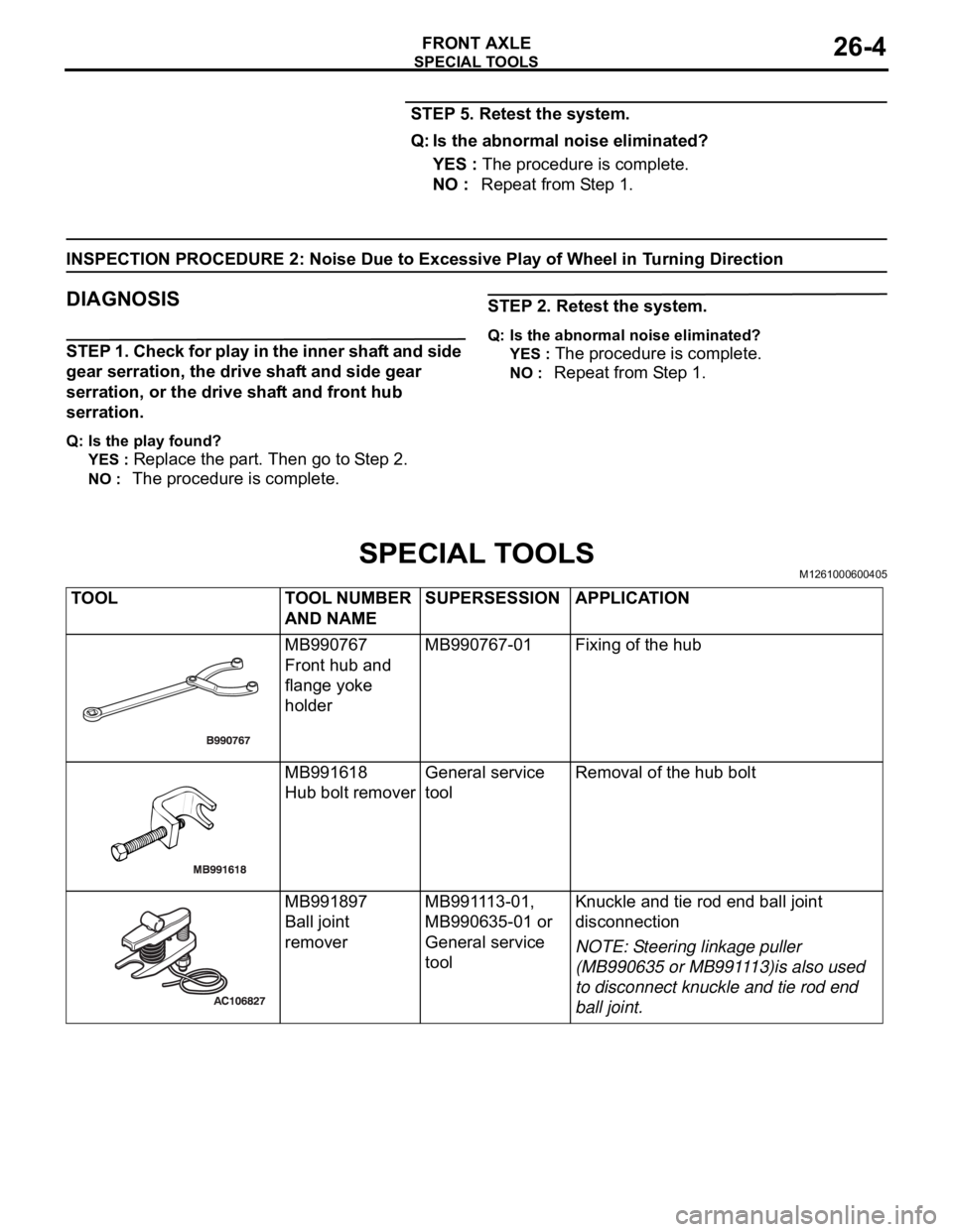
SPECIAL TOOLSM1261000600405
TOOL TOOL NUMBER
AND NAMESUPERSESSION APPLICATION
MB990767
Front hub and
flange yoke
holderMB990767-01 Fixing of the hub
MB991618
Hub bolt removerGeneral service
toolRemoval of the hub bolt
MB991897
Ball joint
removerMB991113-01,
MB990635-01 or
General service
tool Knuckle and tie rod end ball joint
disconnection
NOTE: Steering linkage puller
(MB990635 or MB991113)is also used
to disconnect knuckle and tie rod end
ball joint.
Page 1422 of 1500
SPECIAL TOOLS
FRONT AXLE26-5
MB990241 Axle
shaft puller
A: MB990242
Puller shaft
B: MB990244
Puller barMB990241-01 or
General service
toolRemoval of the drive shaft
MB991354
Puller bodyGeneral service
tool
MB990590 Rear
axle shaft oil seal
remover
A: MB990212
Adapter
B: MB990211
Slide hammer
Removal of the front wheel hub
A: MB991017
B: MB990998
C: MB991000
A, B: Front hub
remover and
installer
C: SpacerMB990998-01
Removal of the hub
Provisional holding of the wheel
bearing
Measurement of hub starting torque
Measurement of wheel bearing end
play
NOTE: MB991000, which belongs to
MB990998, should be used as a
spacer.
MB990685
Torque wrenchGeneral service
toolMeasurement of hub starting torque
MB990326
Preload socketGeneral service
tool
MB990810
Side bearing
pullerGeneral service
tool
Removal of the center bearing
bracket
Removal of the wheel bearing inner
race (outside) TOOL TOOL NUMBER
AND NAMESUPERSESSION APPLICATION