Page 1439 of 1500
DRIVE SHAFT ASSEMBLY
FRONT AXLE26-22
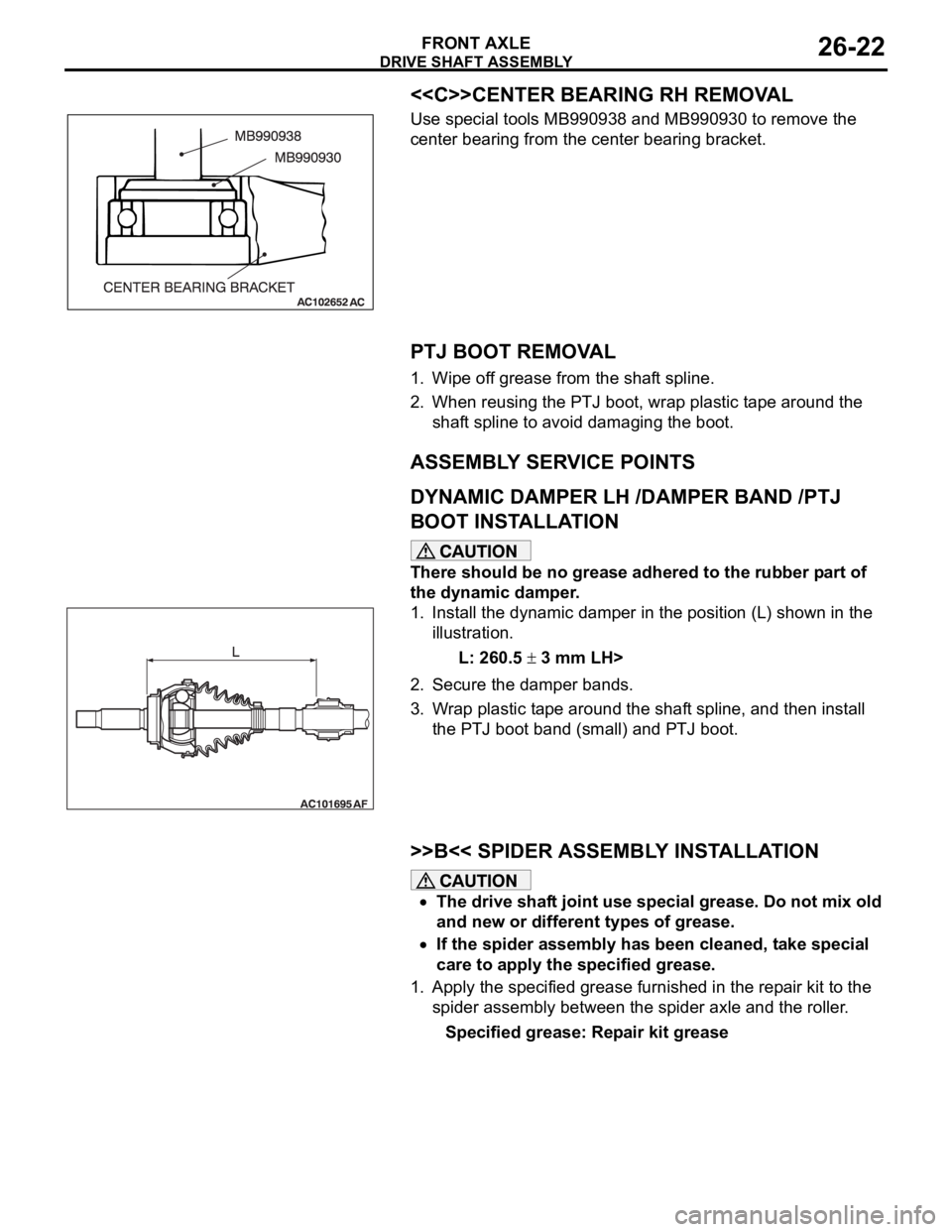
<>CENTER BEARING RH REMOVAL
Use special tools MB990938 and MB990930 to remove the
center bearing from the center bearing bracket.
.
PTJ BOOT REMOVAL
1. Wipe off grease from the shaft spline.
2. When reusing the PTJ boot, wrap plastic tape around the
shaft spline to avoid damaging the boot.
ASSEMBLY SERVICE POINTS
.
DYNAMIC DAMPER LH /DAMPER BAND /PTJ
BOOT INSTALLATION
There should be no grease adhered to the rubber part of
the dynamic damper.
1. Install the dynamic damper in the position (L) shown in the
illustration.
L: 260.5
3 mm LH>
2. Secure the damper bands.
3. Wrap plastic tape around the shaft spline, and then install
the PTJ boot band (small) and PTJ boot.
.
>>B<< SPIDER ASSEMBLY INSTALLATION
The drive shaft joint use special grease. Do not mix old
and new or different types of grease.
If the spider assembly has been cleaned, take special
care to apply the specified grease.
1. Apply the specified grease furnished in the repair kit to the
spider assembly between the spider axle and the roller.
Specified grease: Repair kit grease
Page 1446 of 1500
SPECIFICATIONS
FRONT AXLE26-29
SPECIFICATIONS
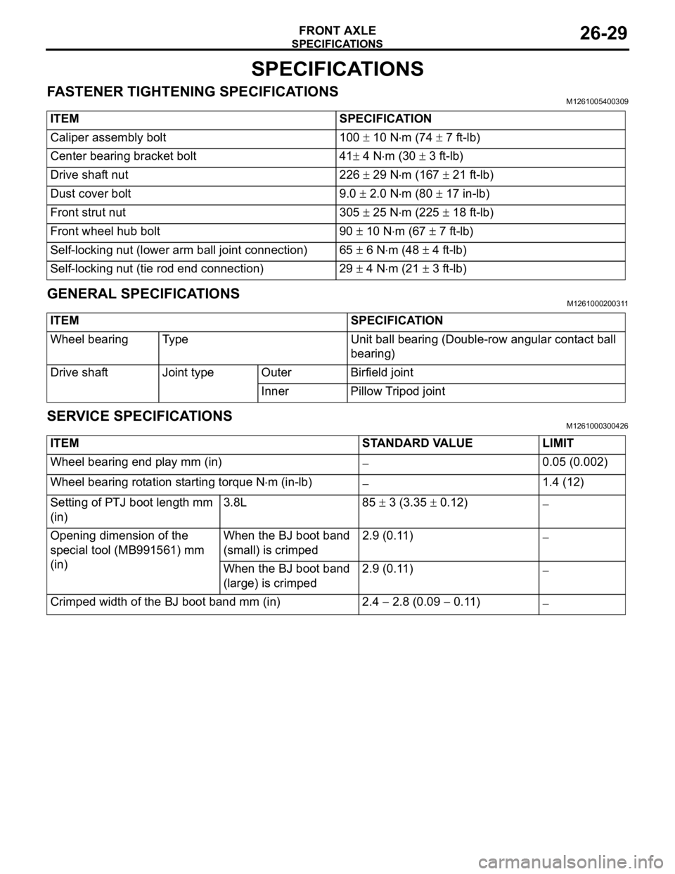
FASTENER TIGHTENING SPECIFICATIONSM1261005400309
GENERAL SPECIFICATIONSM1261000200311
SERVICE SPECIFICATIONSM1261000300426
ITEM SPECIFICATION
Caliper assembly bolt 100
10 Nm (74 7 ft-lb)
Center bearing bracket bolt 41
4 Nm (30 3 ft-lb)
Drive shaft nut 226
29 Nm (167 21 ft-lb)
Dust cover bolt 9.0
2.0 Nm (80 17 in-lb)
Front strut nut 305
25 Nm (225 18 ft-lb)
Front wheel hub bolt 90
10 Nm (67 7 ft-lb)
Self-locking nut (lower arm ball joint connection) 65
6 Nm (48 4 ft-lb)
Self-locking nut (tie rod end connection) 29
4 Nm (21 3 ft-lb)
ITEM SPECIFICATION
Wheel bearing Type Unit ball bearing (Double-row angular contact ball
bearing)
Drive shaft Joint type Outer Birfield joint
Inner Pillow Tripod joint
ITEM STANDARD VALUE LIMIT
Wheel bearing end play mm (in)
0.05 (0.002)
Wheel bearing rotation starting torque N
m (in-lb)1.4 (12)
Setting of PTJ boot length mm
(in)3.8L 85
3 (3.35 0.12)
Opening dimension of the
special tool (MB991561) mm
(in)When the BJ boot band
(small) is crimped2.9 (0.11)
When the BJ boot band
(large) is crimped2.9 (0.11)
Crimped width of the BJ boot band mm (in) 2.4 2.8 (0.09 0.11)
Page 1448 of 1500
27-1
GROUP 27
REAR AXLE
CONTENTS
GENERAL DESCRIPTION. . . . . . . . .27-2
REAR AXLE DIAGNOSIS . . . . . . . . .27-2
INTRODUCTION TO REAR AXLE DIAGNOSIS27-2
REAR AXLE DIAGNOSTIC
TROUBLESHOOTING STRATEGY . . . . . . 27-2
SYMPTOM PROCEDURES . . . . . . . . . . . . 27-3
SPECIAL TOOLS . . . . . . . . . . . . . . . .27-4
ON-VEHICLE SERVICE . . . . . . . . . . .27-4
WHEEL BEARING END PLAY CHECK . . . 27-4
REAR HUB ROTARY-SLIDING RESISTANCE
CHECK . . . . . . . . . . . . . . . . . . . . . . . . . . . . 27-5HUB BOLT REPLACEMENT . . . . . . . . . . . . 27-5
REAR AXLE HUB ASSEMBLY . . . . .27-6
REMOVAL AND INSTALLATION . . . . . . . . 27-6
INSPECTION. . . . . . . . . . . . . . . . . . . . . . . . 27-7
KNUCKLE . . . . . . . . . . . . . . . . . . . . . .27-8
REMOVAL AND INSTALLATION . . . . . . . . 27-8
INSPECTION. . . . . . . . . . . . . . . . . . . . . . . . 27-9
SPECIFICATIONS . . . . . . . . . . . . . . .27-10
FASTENER TIGHTENING SPECIFICATIONS27-10
SERVICE SPECIFICATIONS . . . . . . . . . . . 27-10
Page 1451 of 1500
SPECIAL TOOLS
REAR AXLE27-4
SPECIAL TOOLSM1271000600525
ON-VEHICLE SERVICE
WHEEL BEARING END PLAY CHECKM1271000900474
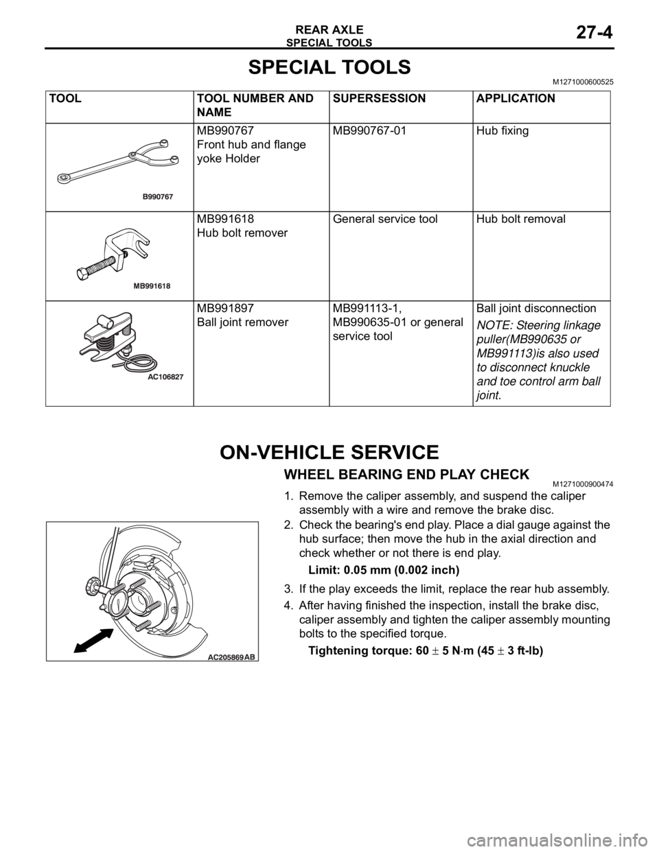
1. Remove the caliper assembly, and suspend the caliper
assembly with a wire and remove the brake disc.
2. Check the bearing's end play. Place a dial gauge against the
hub surface; then move the hub in the axial direction and
check whether or not there is end play.
Limit: 0.05 mm (0.002 inch)
3. If the play exceeds the limit, replace the rear hub assembly.
4. After having finished the inspection, install the brake disc,
caliper assembly and tighten the caliper assembly mounting
bolts to the specified torque.
Tightening torque: 60
5 Nm (45 3 ft-lb) TOOL TOOL NUMBER AND
NAMESUPERSESSION APPLICATION
MB990767
Front hub and flange
yoke HolderMB990767-01 Hub fixing
MB991618
Hub bolt removerGeneral service tool Hub bolt removal
MB991897
Ball joint removerMB991113-1,
MB990635-01 or general
service toolBall joint disconnection
NOTE: Steering linkage
puller(MB990635 or
MB991113)is also used
to disconnect knuckle
and toe control arm ball
joint.
Page 1452 of 1500
ON-VEHICLE SERVICE
REAR AXLE27-5
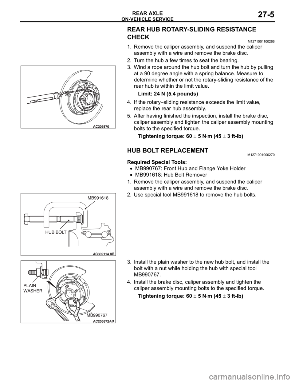
REAR HUB ROTARY-SLIDING RESISTANCE
CHECK
M1271001100266
1. Remove the caliper assembly, and suspend the caliper
assembly with a wire and remove the brake disc.
2. Turn the hub a few times to seat the bearing.
3. Wind a rope around the hub bolt and turn the hub by pulling
at a 90 degree angle with a spring balance. Measure to
determine whether or not the rotary-sliding resistance of the
rear hub is within the limit value.
Limit: 24 N (5.4 pounds)
4. If the rotary
sliding resistance exceeds the limit value,
replace the rear hub assembly.
5. After having finished the inspection, install the brake disc,
caliper assembly and tighten the caliper assembly mounting
bolts to the specified torque.
Tightening torque: 60
5 Nm (45 3 ft-lb)
HUB BOLT REPLACEMENTM1271001000270
Required Special Tools:
MB990767: Front Hub and Flange Yoke Holder
MB991618: Hub Bolt Remover
1. Remove the caliper assembly, and suspend the caliper
assembly with a wire and remove the brake disc.
2. Use special tool MB991618 to remove the hub bolts.
3. Install the plain washer to the new hub bolt, and install the
bolt with a nut while holding the hub with special tool
MB990767.
4. Install the brake disc, caliper assembly and tighten the
caliper assembly mounting bolts to the specified torque.
Tightening torque: 60
5 Nm (45 3 ft-lb)
Page 1453 of 1500
Page 1456 of 1500
Page 1457 of 1500
SPECIFICATIONS
REAR AXLE27-10
SPECIFICATIONS
FASTENER TIGHTENING SPECIFICATIONSM1271004000332
SERVICE SPECIFICATIONSM1271000300502
ITEM SPECIFICATION
Knuckle Lower arm assembly to knuckle nut 113
12 Nm (83 9 ft-lb)
Shock absorber assembly to knuckle
bolt100
10 Nm (74 7 ft-lb)
Self locking nut (toe control arm
connection)66
6 Nm (49 4 ft-lb)
Trailing arm assembly to knuckle nut 113
12 Nm (83 9 ft-lb)
Upper arm assembly to knuckle nut 113
12 Nm (83 9 ft-lb)
Rear axle hub assembly Brake caliper assembly bolt 60
5 Nm (45 3 ft-lb)
Rear hub assembly bolt 73
7 Nm (54 5 ft-lb)
ITEM LIMIT
Wheel bearing end play mm (in) 0.05 (0.002)
Rear hub rotary-sliding resistance N (lb) 24 (5.4)